Note: Descriptions are shown in the official language in which they were submitted.
CA 02584212 2007-04-13
WO 2006/043074 PCT/GB2005/004060
1
Keypad Security Device
The present invention relates to data entry keypad security and in particular,
though not
exclusively, to the security of data entry keypads fitted to ATMs (Automated
Teller
Machines), retail Chip and PIN (Personal Identification Number) EPOS
(Electronic
Point Of Sale) systems and PEDs (PIN Entry Devices).
In recent years there has been an increase in crime related to the fraudulent
use of cash
cards to withdraw money from ATMs. In order to perpetrate such a crime a
criminal
will usually need obtain details of a legitimate users cash card together with
the PIN
needed to activate the card. Obtaining the PIN may be achieved in a number of
ways
when a legitimate user uses an ATM. A criminal may simply stand close to the
user
and observe the user keying in their PIN, a practice commonly referred to as
shoulder
surfing. More sophisticated methods of obtaining PINs involve the positioning
of a
camera in the vicinity of an ATM which is able to view the keypad. Similar
security
concerns exist at point of sale PIN entry devices which are increasingly
common in the
retail environment.
According to the present invention there is provided a keypad security device
comprising an enclosure having a viewing aperture and an access aperture, the
enclosure at least partially surrounding a keypad such that the keypad is
viewable
through the viewing aperture and accessible by a user through the access
aperture, the
viewing aperture including a security pane arranged so as to permit the keypad
to be
viewed clearly from the point of view of a user of the keypad and to prevent
the keypad
from being viewed from the point of view of a person other than the user,
wherein the
security pane includes a refractive lens
The keypad enclosure shields the keypad and prevents the keystrokes made by
the user
from being observed. The security pane enables a user to observe the keypad
both
before and during use but prevents a person standing close to the user from
observing
the keystrokes made by the user through the security pane. The security pane
also
CA 02584212 2007-04-13
WO 2006/043074 PCT/GB2005/004060
2
keystrokes made by the user from being observed remotely, for example by
a camera positioned outside of the enclosure in the vicinity of the keypad.
The security pane is positioned in the viewing aperture such that a viewing
axis extends
therethrough to the keypad. A person aligning themselves with the viewing axis
so as
to view the keypad along the axis is able to view the keypad in a clear
manner. Should
an attempt be made to view the keypad through the security pane along an axis
other
than the viewing axis, then the security pane either partially or wholly
distorts and/or
obscures the view of the keypad. The viewing axis may be substantially
perpendicular
to the security pane. The viewing axis may be substantially perpendicular to
the
security pane and the keypad. The security pane may be provided with a
plurality of
viewing axes along which the keypad may be viewed in a clear and undistorted
or
unobscured manner. Such a plurality of axes may define a viewing corridor
through
which the keypad may be viewed clearly.
In one embodiment the security pane may comprise a lens which in use alters
the view
of the keypad observed by a user when viewing the keypad through the pane. In
a
preferred embodiment the lens is a magnifying lens. The lens preferably has
the ability
to both magnify and distort what is viewed therethrough. The lens preferably
has a
refractive index of between 1.3 and 1.8. More preferably the lens has a
refractive index
of between 1.4 and 1.7. The lens may have a refractive index of between 1.45
and 1.65,
or, alternatively, have a refractive index of between 1.47 and 1.61. In one
embodiment
the lens may be manufactured from acrylic and have a refractive index of
between 1.47
and 1.51. Alternatively, the lens may manufactured from vinyl chloride and
have a
refractive index of between 1.52 and 1.56. In a further embodiment the lens
may be
manufactured from polyethylene and have a refractive index of between 1.49 and
1.53.
In yet a further embodiment the lens may be manufactured from polycarbonate
and have
a refractive index of between 1.57 and 1.61.
The lens may be a fresnel lens or the like. The term fresnel lens is intended
to cover
lenses which utilise a texture applied to the surface thereof to achieve
desired image
alteration characteristics. The texture may enhance and/or complement image
alteration
CA 02584212 2007-04-13
WO 2006/043074 PCT/GB2005/004060
3
[cs of a lens which result from the shape of the lens. The pane may be
provided with a plurality of lenses each of which may be aligned with one or
more of
the keys of the keypad. The security pane may include an image which permits
the
keypad to be viewed therethrough along the viewing axis or corridor but which
obscures the keypad when viewed along an axis not aligned with the viewing
axis of
falling within the viewing corridor. The image may be provided on or in the
security
pane. For example the image may be etched or otherwise applied to a surface of
the
security pane. Alternatively the image may be embedded within the security
pane. In
such an embodiment the image may be a holographic image.
The security pane may comprise a unitary member comprised of a plastics
material such
as polycarbonate or a vitreous material such as glass. The security pane may
be of
laminar construction. In such an embodiment the pane may comprises upper and
lower
planar members between which is located the lens. The planar members may have
substantially the same shape as one another and the lens. The pane may be
incorporated
in the enclosure during the manufacture thereof, for example the pane may be
incorporated into the enclosure during moulding of the enclosure from a
plastics
material. Alternatively, the security pane may be removable from the
enclosure. The
pane is thus able to be replaced if, for example, it becomes damaged or
scratched.
,
The enclosure may comprise a wall arranged so as to at least partially
surround the
keypad. The enclosure may alternatively comprise a plurality of walls arranged
so as to
at least partially surround the keypad. The access aperture may by defined by
an
aperture provided in the wall or one of the plurality of walls. Alternatively
the access
aperture may be defined by a gap or space provided between two walls. The or
each
wall may be provided with a window arranged so as to permit light to enter the
enclosure while preventing the keypad to be viewed therethrough. The window
preferably includes glazing pane which is translucent, frosted, opaque or
otherwise
treated so as to prevent the keypad to be viewed therethrough. The or each
wall may be
a wall of a base to which a keypad is attached or mounted. In such an instance
the
security pane may be contained within a member which is mountable to the or
each
wall.
CA 02584212 2007-04-13
WO 2006/043074 PCT/GB2005/004060
4
The enclosure may be provided with an additional access aperture. In use, the
additional access aperture may be aligned with a feature of a device to which
the
keypad is fitted. For example the additional access aperture may be aligned
with a a
banknote dispensing slot of an ATM. The presence of the additional access
aperture
permits a user to reach the banknote dispensing slot through the enclosure. It
will thus
be appreciated that the enclosure may provide a shielding function for the
dispensing
slot to prevent unauthorised access to banknotes dispensed therethrough.
Preferably the
additional access aperture is provided on an opposite side of the enclosure to
the keypad
access aperture to allow a user to easily reach through the enclosure.
The viewing aperture is preferably provided in a portion of the enclosure
overlying the
wall or walls. Preferably the viewing aperture is aligned with a plane which
is
substantially parallel to the plane of the keypad.
Embodiments of the present invention will now be described with reference to
the
accompanying drawings in which:
Figure 1 shows an exploded perspective view of a security device according
to a first embodiment of the present invention;
Figure 2 shows a perspective view of the device of figure 1 in an assembled
state;
Figure 3 shows a n exploded perspective view of a security device
according to a further embodiment of the present invention;
Figure 4 shows a perspective view of the device of figure 3 in an assembled
state;
Figure 5 shows a schematic side view of a device according to the present
invention fitted to an ATM;
Figures 6 to 8 show views of an ATM keypad through a device according to
the present invention;
Figure 9 shows a perspective view of a security device enclosure according
to the present invention;
CA 02584212 2007-04-13
WO 2006/043074 PCT/GB2005/004060
Figures 10 and 11 show perspective views of an EPOS variant of a security
device according to the present invention;
Figure 12 shows a perspective view of an ATM keypad security device
-according to the present invention;
5 Figure 13 shows a side view of the alignment of the security pane of the
device of figure 12 relative to the keypad; and
Figures 14 and 15 show a perspective views of two further EPOS/PED
variants of the security device.
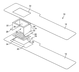
Referring firstly to figures 1 and 2 there is shown a keypad security device
according to
the present invention generally designated 10. The device 10 comprises a base
plate 12,
an enclosure 14, a top plate 16 and a viewing pane arrangement 18. The base
plate 12
is formed from a thin sheet of material such as, for example, steel and is
shaped to fit to
a front panel of an ATM. The base plate 12 is provided with an aperture 20
which is
sized and shaped so as to be larger than the data entry keypad (not shown) of
an ATM.
It will be understood that the aperture 20 is positioned in the base plate
such that the
keypad is fully accessible therethrough when the base plate 12 is fitted to an
ATM.
The enclosure 14 is formed from a single piece of thin sheet material, such as
steel or
aluminium alloy, and includes a pair of spaced side walls 22 joined by
bridging portion
24. The bridging portion is provided with a viewing aperture 26, while the
base of each
wall 22 is provided with a laterally extending flange 28. The aperture 20 of
the base
plate 12 is sized so as to be able to receive the flanges 28 such that they
fit flush with
the base plate 12. It will be appreciated that the enclosure 14 may
conveniently be
formed by conventional stamping and pressing operations. The orientation of
the side
walls 22 and bridging portion 24 define an access aperture 30 into which a
user may
place their hand when the device 10 is fitted to an ATM. Optionally the
enclosure may
be provided with a further wall, hereinafter referred to as a rear wall,
opposite to the
access aperture and extending between the side walls 22 and the bridging
portion 24.
The top plate 16 is of a similar construction to that of the base plate 12 in
that it is
formed from a thin sheet of material such as steel and is provided with an
aperture 32
CA 02584212 2007-04-13
WO 2006/043074 PCT/GB2005/004060
6
- iich the enclosure 14 projects, in use, The top plate aperture 32 is sized
and
shaped such that the top plate 16 overlies the flanges 28 the enclosure. The
viewing
plate arrangement 18 comprises a backing plate 34 and a security pane 36. The
backing
plate 34 and security pane 36 are fittable to the enclosure viewing aperture
in a manner
which prevents their removal therefrom. The backing plate 34 is sufficiently
transparent so as to allow the ATM keypad to be viewed therethrough. The
backing
plate 24 may be formed from a plastics material such as, for example,
polycarbonate.
Alternatively the backing plate may be manufactured from a toughened glass.
The
security pane 36 is configured so as to permit the ATM keypad to be viewed
therethrough from certain user viewing positions and to prevent the ATM keypad
from
being viewed from other user viewing positions. Operation of the security pane
36 will
be described in greater detail below.
The assembled device 10 is shown in figure 2. In use, a user wishing to use an
ATM
having the device 10 fitted approaches the ATM and inserts their card in the
conventional manner. When prompted to enter their PIN the user inserts their
hand into
through the access aperture 30 and positions themselves so that they are able
to view
the ATM keypad through the viewing aperture 26. Persons other than the user
are
prevented from viewing the keypad by the presence of the enclosure side walls
22,
optional back wall and the security pane 36.
Referring now to figures 3 and 4 there is shown an alternative embodiment of a
keypad
security device according to the present invention and generally designated
40. The
device 40 comprises a pair of base plates 42,44, an enclosure 46, a glazing
member 48
and support 50 including a security pane 52. The base plates 42,44 are
fittable to the
keypad area of an ATM and are each provided with an aperture 43,45 through
which
the keypad may accessed. The base plates 42,44 are formed from a thin sheet of
material such as, for example, steel. The enclosure 46 is formed from a thin
sheet of
material such as, for example, steel and comprises a pair of side walls 54 and
a rear wall
56. Each wall 54,56 is provided with an aperture 58. The glazing member 48
comprises a sheet of plastics material such as, for example, polycarbonate
which is
formed into a shape complimentary to that of the enclosure 46. The glazing
member 48
CA 02584212 2007-04-13
WO 2006/043074 PCT/GB2005/004060
7
~ the enclosure 46 so as to overlie the apertures 58 of the enclosure walls
54,56. The glazing member 48 is opaque yet sufficiently transparent so as to
allow light
to pass therethrough and illuminate the interior of the enclosure 46 and the
keypad, but
is configured so as to prevent the keypad being viewed therethrough. The
glazing
member 48 may, for example, by frosted or be provided with a crazed, light
scattering
surface treatment.
The support 50 includes a frame portion 60 and a pair of legs 62. The frame
portion 60
is sized and shaped to fit to the upper region of the enclosure 46 bounded by
the walls
54,56. The legs 62 are arranged to fit to the side walls 54 so as to define an
access
aperture 64 through which a user may reach the ATM keypad. The security pane
52 is
incorporated into the frame portion 60, while the support 50 and the glazing
member 48
are fittable to the enclosure so as to be difficult to remove therefrom. The
security pane
52 is configured so as to permit the ATM keypad to be viewed therethrough from
certain user viewing positions and to prevent the ATM keypad from being viewed
from
other user viewing positions.
The assembled device 40 is shown in figure 4. In use, a user wishing to use an
ATM
having the device 40 fitted approaches the ATM and inserts their card in the
conventional manner. When prompted to enter their PIN the user inserts their
hand into
the access aperture 64 and positions themselves so that they are able to view
the ATM
keypad through the security pane 52. Persons other than the user are prevented
from
viewing the keypad by the presence of the enclosure walls 54,56 and the
security pane
52.
As described above the security pane 36,52 is arranged such that the keypad
may be
clearly viewed from certain viewing positions while being prevented from being
viewed
from other positions. In one embodiment the security pane 36,52 may include a
lens
which permits a magnified view of the keypad when a user looks through the
pane
36,52 from a certain angle and yet provides a distorted view of the keypad
when viewed
from other angles. Figure 5 shows a schematic view of an ATM 70 having a
keypad 72
CA 02584212 2007-04-13
WO 2006/043074 PCT/GB2005/004060
8
e 10,40 according to the present invention. The device 10,40 is provided
with a magnifying lens 74 such as, for example, a fresnel lens. Above the
device 10,40
there is defined a viewing corridor 76 the cross-sectional dimensions of which
correspond substantially to those of the lens 74. A person viewing the keypad
72
through the lens along an axis 78 lying within the corridor and substantially
perpendicular to the lens 74 and keypad 72 will be able to view a magnified
image of
the full keypad as illustrated in figure 6. Should a person attempt to view
the along an
axis 80 which is not perpendicular to the lens and keypad and which extends
out of the
viewing corridor is presented with a distorted image of the keypad 72.
Examples of the
type of view which may be observed are shown in figures 7 and 8. In figure 7
the lower
portion of the keypad 72 is obscured including the 0 key, while in figure 8
the upper
portion the keypad including the 1,2 and 3 keys is obscured.
The security pane may take forms other than that of a lens. For example, the
pane may
have retained therein or thereupon an image through which the keypad may be
viewed
by a user, but which occludes the view of the keypad from viewing angles other
than
those utilised by a legitimate user of the keypad. For example, the security
pane may
include a holographic image which is hidden to a legitimate user of the
device. In a
further embodiment the security pane may include a plurality of windows
aligned with
keys of the keypad. Each window may include a lens, retained image or a
combination
of the two.
Referring now to figure 9 there is shown an alternative embodiment of a
security device
generally designated 82. Features common to previously described embodiments
are
identified with like reference numerals. The device 82 comprises an enclosure
having a
pair of spaced side walls 22 joined by a bridging portion 24. Within the
bridging
portion 24 there is provided a viewing aperture 26 into which a security pane
(not
shown) may be retained. The walls 22 and bridging portion 24 define an access
aperture 30 into which a user may place their hand when the device 82 is
fitted over a
keypad. The enclosure is manufactured as a single piece item from a toughened
plastics material by a moulding operation. Alternatively, the enclosure may be
formed
from metal such as, for example, Aluminium alloy. The security pane may be
CA 02584212 2007-04-13
WO 2006/043074 PCT/GB2005/004060
9
i into the enclosure during moulding thereof. Alternatively the pane may be
retrofitted to the enclosure after it has been moulded.
The device 82 is further provided with a plurality of spaced holes 84 along an
edge of
the bridging portion 24 opposite to the access aperture 30. The holes 84 let
light into
the space surrounded by the enclosure while not permitting the keypad to be
directly
viewed therethrough. It will be appreciated that the walls 22 and bridging
portion 24
define another additional access aperture 85 on the opposite side of the
enclosure. On
certain configurations of ATM the slot through which bank notes are dispensed
is
positioned in front of and slightly above the keypad. In such a configuration
a user is
able to take the bank notes dispensed with the same hand as that used to input
their PIN
to the keypad. The provision of the additional access aperture 85 enables a
user to
reach the banknotes while the device 82 as a whole shields the slot through
which they
are dispensed and thus prevents them from being snatched by a person other
than the
user of the ATM.
Figures 10 shows a security device generally designated 86 according to the
present
invention which is configured for use with a chip and pin keypad 88. Features
common
to the previously described embodiments are identified with like reference
numerals.
The device comprises an enclosure 90 having a base 92, a pair of spaced side
walls 22
and a bridging portion 24 extending therebetween. The bridging portion 24
includes a
viewing aperture 26 within which may be retained a security pane (not shown).
In the
embodiment shown the base 92, side walls 22 and bridging portion 24 are
moulded in a
single piece from a plastics material. Advantageously the security pane may be
incorporated into the enclosure 90 during moulding thereof.
An access aperture 30 is provided in one side of the enclosure 90, while an
additional
access aperture 94 is provided in the opposing side thereof. The access
aperture 30
permits a user to reach the keypad 88, while the additional aperture 94
permits the user
or a counter assistant to insert a chip card into the keypad 88 if required to
do so. The
bridging portion 24 is provided with a plurality of holes 96 which permit
ambient light
to enter the enclosure 92 without permitting the keypad to be viewed in its
entirety.
CA 02584212 2007-04-13
WO 2006/043074 PCT/GB2005/004060
Figure 11 shows a security device 98 similar to that figure 10 and common
features are
identified with like reference numerals. The device 98 differs in that it is
provided with
a larger viewing aperture 26 and does not include the lighting holes. The
device 98 is
5 mounted to a flexible stem 100 which in turn is connected to a foot 102
which enables
the device to be mounted at a point of sale position.
Referring now to figures 12 and 13 there is shown a further embodiment of a
security
device according to the present invention and generally designated 104.
Features
10 common to the previously described embodiments are identified with like
reference
numerals. The device 104 is similar to that described with reference to figure
9. The
device 104 comprises an enclosure having a pair of spaced side walls 22 joined
by a
bridging portion 24. Within the bridging portion 24 there is provided a
viewing
aperture 26 into which a security pane (not shown) may be retained. The walls
22 and
bridging portion 24 define an access aperture 30 into which a user may place
their hand
when the enclosure is fitted over a keypad. The enclosure 82 is manufactured
as a
single piece item from a toughened plastics material by a moulding operation.
Alternatively, the enclosure 82 may be manufactured from metal such as
aluminium
alloy by a casting operation. The security pane may be incorporated into the
enclosure
during moulding thereof. Alternatively the pane may be retrofitted to the
enclosure
after it has been manufactured.
The enclosure is further provided with a plurality of spaced holes 84 around
the viewing
aperture 26. The holes 84 let light into the space surrounded by the enclosure
82 while
not permitting the keypad to be directly viewed therethrough. It will be
appreciated that
the walls 22 and bridging portion 24 define another additional access aperture
85 on the
opposite side of the enclosure. On certain configurations of ATM the slot
through
which bank notes are dispensed is positioned in front of and slightly above
the keypad.
In such a configuration a user is able to take the bank notes dispensed with
the same
hand as that used to input their PIN to the keypad. The provision of the
additional
access aperture 85 enables a user to reach the banknotes while the device 82
as a whole
CA 02584212 2007-04-13
WO 2006/043074 PCT/GB2005/004060
11
slot through which they are dispensed and thus prevents them from being
snatched by a person other than the user of the ATM.
The enclosure is preferably moulded from a translucent plastics material which
permits
a degree of light transmission therethrough while at the same time not
permitting the
keypad to be viewed through the walls 22 and bridging portion 24 surrounding
the
viewing aperture 26. The translucent nature of the plastics material enables a
user or
operator of the ATM to readily see if anything, such as a miniature camera,
has been
attached to the inner surface of the enclosure. The inner surfaces of the
enclosure may
additionally be textured so as make it difficult for a device such as a
miniature camera
to be attached thereto. For example, the inner surfaces of the enclosure may
be ribbed
or ridged.
The device 104 may be mounted to the ATM bay any appropriate fixing means. In
the
embodiment shown the bottom edge 106 of each wall 22 is provided with
projections
108 which extend through corresponding apertures of the ATM. The projections
108
may be threaded so as to receive nuts thereupon. Alternatively, the lower edge
of each
wall 22 may be provided with a flange through which appropriate fixing means
may
extend.
The device 104 may be mounted to the ATM such that the viewing aperture 26 and
security pane 36 are not fully in register with the keypad. Figure 13 shows an
example
of such an alignment between the viewing aperture 26, security pane 36 and
keypad
110. The upper edge 112 of the viewing aperture 26 and security pane 36 is
aligned
with the lower edge 114 of the upper row of keys 116 of the keypad 110. This
out of
register alignment ensures that a user of the ATM keypad 110 is able to fully
view the
keypad 110 through the security pane 36, while persons attempting to view the
keypad
form positions other than that corresponding to the point of view of the user,
either over
the shoulder of the user or remotely via a camera mounted above or near the
ATM, are
unable to view the full keypad through the security pane 36.
CA 02584212 2007-04-13
WO 2006/043074 PCT/GB2005/004060
12
c)w to figure 14 there is shown a device generally designated 118 which is
configured for use with a EPOS chip and pin keypad PED 88 of the type now
utilised
by retailers. The device 118 is similar to that described with reference to
figures 10 and
11 and features common thereto are identified with like reference numerals.
The device 118 comprises an enclosure 120 having a base 92 and a pair of
spaced side
walls 22. The base 92 and walls 22 are formed from a single piece material.
For
example the base 92 and walls 22 may be formed from a plastics material by a
moulding operation. Alternatively, the enclosure may be manufactured from a
metal
such as aluminium alloy. Extending between the upper edges 122 of the walls 22
is a
frame 124 defining the viewing aperture 26 and within which the security pane
(not
shown) may be mounted. The frame 124 is pivotably connected by a hinge 126 to
one
of the walls 22, while a catch arrangement (not shown) may be provided between
the
frame 124 and the other of the walls in order to retain the frame 124 in the
position
shown.
An access aperture 30 is provided to the front of the enclosure 120, while an
additional
access aperture 94 is provided to the rear thereof. The term "front" is
construed with
reference to the edge of the keypad 88 closest to the user thereof. The access
aperture
30 permits a user to reach the keypad 88, while the additional aperture 94
permits the
user or a counter assistant to insert a chip card into a card receiving slot
of the keypad
88 if required to do so. The frame 124 and security pane are pivotable in the
direction
indicated by arrow 128. It will be understood that that the frame 124 and
security pane
may be pivoted upwards and away from the keypad 88. The security pane may thus
be
moved out of the line of sight user with respect to the keypad 88. This may be
required
in instances where a user has difficulty in viewing the keypad through the
security pane.
The security pane may also be moved so as to enable a PIN card to be inserted
into a
slot on the upper face of the key pad 88. With the card inserted the security
pane can be
moved back into position ready for a user to key in their PIN.
The base 92 of the enclosure 120 is mounted to a post or pedestal 136. The
base 92 is
mounted so as to be both rota table relative to the pedestal 136 as indicated
by arrow
CA 02584212 2007-04-13
WO 2006/043074 PCT/GB2005/004060
13
otable relative to the pedestal 136 as indicated by arrow 140. The base 92 is
removably mounted to the pedestal 136 so that the enclosure 120 and keypad 88
as a
whole can be demounted and handed to a user.
It will be appreciated that the frame 124 may be movably connected to a wall
of the
enclosure 120 by other means. For example, the frame 124 may be slidably
mounted to
one or both walls 22 of the enclosure 120. In an alternative embodiment, the
frame 124
may be fully removable.
Figure 15 shows a further embodiment of a device generally designated 130
which is
configured for use with a EPOS chip and pin keypad 88 of the type now utilised
by
retailers. The device 130 is similar to that described with reference to
figures 10, 11
and 14, and features common thereto are identified with like reference
numerals.
The device 130 comprises an open sided enclosure 132 having a base 134 and
curved
side wall 22. The enclosure 132 is mounted to a pedestal 136. The base 134 and
wall
22 are formed from a single piece material. For example the base 134 and
wa1122 may
be formed from a plastics material by a moulding operation. Extending from the
upper
edge 122 of the wall 22 is a frame 124 defining the viewing aperture 26 and
within
which the security pane (not shown) may be mounted. The frame 124 is pivotably
connected by a hinge 126 to the upper edge 122 of the wall 22.
An access aperture 30 is provided to the front of the enclosure 120, while an
additional
access aperture 94 is provided to the rear thereof. The access aperture 30
permits a user
to reach the keypad 88, while the additional aperture 94 permits the user or a
counter
assistant to insert a chip card into a card receiving slot of the keypad 88 if
required to do
so. The frame 124 and security pane are pivotable in the direction indicated
by arrow
128. It will be understood that that the frame 124 and security pane may be
pivoted
upwards and away from the keypad 88. The security pane may thus be moved out
of
the line of sight user with respect to the keypad 88. This may be required in
instances
where a user has difficulty in viewing the keypad through the security pane.
CA 02584212 2007-04-13
WO 2006/043074 PCT/GB2005/004060
14
ppreciated that the frame 124 may be movably connected to a wall of the
enclosure 132 by other means. For example, the frame 124 may be slidably
mounted to
the wall 22 of the enclosure 132. In an alteirnative embodiment, the frame 124
may be
fully removable.
The device 130 may be provided with an additional wall member (not shown)
which
may be fitted to the base 134 so as to configure the enclosure 132 in a
similar manner to
that shown in figure 14. The additional wall member may be removed, and the
frame
124 pivoted to the position shown in figure 15 to permit the keypad 88 to be
removed
from the enclosure 132 and handed to a user.
The enclosures of the embodiment of the present invention hereinbefore
described may
be adapted to include illumination means operable in low light conditions to
illuminate
the keypad. The illumination means may also be arranged to conduct light out
from the
enclosure through the security pane. Light directed in this manner may prevent
a
camera or the like viewing keystrokes made on the keypad.
The embodiments of the invention described above refer to keypads fitted to
ATMs and
EPOS PIN entry devices or PEDs. It will be appreciated that the invention may
be used
in conjunction with other keypads such as, for example, those used in
connection with
security door entry keypads, and alarm system command keypads to name but a
few. A
device according to the present invention may fitted to a keypad during the
initial
manufacture thereof or the initial incorporation of the keypad into a larger
device.
Alternatively a device according to the present invention may be retrofitted
to a keypad
already incorporated into a larger device.