Note: Descriptions are shown in the official language in which they were submitted.
CA 02584386 2007-04-11
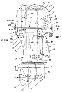
OUTBOARD ENGINE UNIT
FIELD OF THE INVENTION
[0001]
The present invention relates to an outboard engine unit in which
left and right cover members, defining a lower half section of an engine room,
are mounted to and supported by an engine or engine support structure, and
which facilitates detachment/re-attachment of left and right cover members.
The present invention also relates to an outboard engine unit which
facilitates
maintenance work, such as detachment/attachment of an ignition plug.
BACKGROUND OF THE INVENTION
[0002]
In recent years, there have been known outboard engine units of a
type in which a lower half section of an engine room is defined by a lower
cover
composed of resin-made left and right (i.e., port- and starboard-side) cover
members (e.g., Japanese Patent Application Laid-Open Publication Nos. 2004-
338463 and 2001-199393 which will hereinafter be referred to as patent
literature 1 and patent literature 2, respectively).
[0003]
In the outboard engine unit disclosed in patent literature 1, the left
and right cover members of the lower cover are bolted together in
directly-abutted relation to each other. In the outboard engine unit disclosed
in patent literature 2, an under cover (i.e., lower cover) is fixed to an
engine
body, and left and right cover halves (i.e., left and right cover members) of
the
under cover are bolted together in abutted relation to each other.
[0004]
With both of the outboard engine units disclosed in patent
literature 1 and patent literature 2, it is necessary to position a fixed
section of
the body of the outboard engine unit close to respective abutting portions of
the
left and right cover members, in order to reliably achieve appropriate
abutment
between the abutting portions of the cover members; actually, the left and
right
cover members are fastened together by common bolts passed through their
- -
CA 02584386 2007-04-11
respective abutting portions and fixed section.
[0005] However, with the aforementioned conventionally-known outboard
engine units, when one of the left and right cover members is removed or
detached for desired maintenance work, fixation of the other cover member
would become unstable. Thus, in re-assembling of the cover, properly
positioning the left and right covers etc. would require a considerable time
and
labor, which disadvantageously results in poor workability.
[0006] In the aforementioned conventionally-known outboard engine
units,
there are further provided an auxiliary exhaust outlet for discharging a
portion
of engine exhaust to the outside, and a water pilot hole for discharging a
portion of engine cooling water to the outside of the engine room. Sealing
structure for sealing the auxiliary exhaust outlet is attached to either or
both of
the abutting portions of the port-side and starboard-side cover members.
Thus, when any of the cover members is to be detached, it is also necessary to
detach the sealing structure, and thus, the detaching operation and subsequent
re-assembling operation would become cumbersome, which disadvantageously
result in poor workability. Further, a tube of the water pilot hole
(hereinafter
"water pilot tube") etc. are supported directed by the left and right cover
members. Thus, when any of the cover members is to be detached, there
arises a need to detach the water pilot tube, and thus, the detaching
operation
and subsequent re-assembling operation would become cumbersome, which
also disadvantageously result in poor workability.
[0007] There have also been known outboard engine units of a type in
which the axis of engine cylinders is offset relative to the axis of a
crankshaft
(e.g., Japanese Patent Application Laid-open Publication No. 2001-115817,
which will hereinafter be referred to as patent literature 3). According to
the
disclosure of patent literature 3, the engine cylinder axis is offset relative
to the
crankshaft axis by a predetermined distance in a direction where a thrust
force
- 2 -
CA 02584386 2013-05-10
92751-62
acts on a piston. Ignition plug is provided on the inner surface of a cylinder
head. Thus, in
order to secure a sufficient space for performing maintenance work of the
ignition plug, it is
necessary to
(a) increase the size of a bottom cowling (i.e., lower cover) to thereby
secure a
sufficient space within the bottom cowling, or
(b) lower the lower end position of a top cowling (i.e., engine cover) so that
the ignition plug is exposed sideways when the top cowling is removed.
[0008] If the above (a) option is taken, the increased size of the
bottom cowling leads
to an increased size of the top cowling because the bottom cowling and top
cowling are
vertically joined together in edge-to-edge abutted relation, with the result
that the overall size
of the outboard engine unit and weight of the top cowling would significantly
increase.
Further, if the above (b) option is taken, lowering the lower end position of
the top cowling
leads not only to an even greater concave depth of the top cowling, having a
deep bowl shape,
but also to an increased size and weight of the top cowling, as a result of
which operation for
detaching the top cowling tends to be cumbersome and troublesome.
[0009] Generally, the outboard engine units employ a vertical engine
with a vertically-
oriented crankshaft and horizontally-oriented cylinders; especially, the high-
power outboard
engine units employ a four-stroke engine with a plurality of cylinders. In
such outboard
engine units, a plurality of cylinders (e.g. four cylinders in the case of a
four-cylinder engine)
are disposed in a vertical arrangement with a great vertical interval between
the uppermost
cylinder and the lowermost cylinder. With such plural-cylinder engines, the
engine body
unavoidably has an increased vertical length, as a result of which the bow-
shaped top cowling
tends to have an even greater depth.
SUMMARY OF THE INVENTION
[0010] In view of the foregoing prior art problems, in some
embodiments the present
invention may provide an improved outboard engine unit which allows any one of
left and
right cover members to be readily detached and re-attached, without adversely
influencing the
- 3 -
CA 02584386 2013-05-10
92751-62
other cover member and without being interfered with by the presence of an
exhaust outlet
port and water pilot hole, and thereby permits disassembly/re-assembly of the
cover.
100 11] In some embodiments, the outboard engine unit may allow
maintenance work
of an ignition plug, disposed in a lower region within an engine room, to be
performed with an
increased ease without a need for substantially lowering the lower end
position of an engine
cover (top cowling), and which allows maintenance work of an ignition plug to
be performed
with ease without a need for disassembling or detaching a lower cover (bottom
cowling).
[0012] According to an aspect of the present invention, there is
provided an outboard
engine unit comprising: a cover assembly defining a lower half of an engine
room having an
engine accommodated therein, said cover assembly comprising left and right
cover members
each formed of resin; and a bracket fixed to a rear portion of the engine or
engine support
structure, said left and right cover members being fixed at respective rear
portions thereof to
said bracket, wherein said bracket has grooves, formed in opposite side edges
thereof, for
engaging predetermined joining edges of said left and right cover members.
100131 In the outboard engine unit of at least some embodiments of the
invention,
where the bracket is fixed to a rear portion of the engine or engine support
structure and the
left and right cover members are fixed at their respective rear portions to
the bracket, each one
of the left and right cover members can be detached and re-attached from and
to the bracket
independently of the other of the cover members. Thus, the present invention
can significantly
facilitate disassembly and re-assembly of the cover assembly, e.g. for
maintenance work, and
achieve greatly-enhanced workability, as compared to the prior art. Further,
because it is only
necessary to provide the bracket, fix the bracket to a rear portion of
- 4 -
CA 02584386 2007-04-11
the engine or the like, abut the respective joining edges against the bracket
and
then individually fix the joining edges of the cover members to the bracket by
means of a bolt or otherwise. Thus, the present invention can significantly
simplify the abuttingly-joining construction of the cover members and hence
the construction of the outboard engine unit.
[0014]
In an embodiment of the invention, the bracket has engaging
grooves, formed in its opposite side edges, for engaging the predetermined
joining edges of the left and right cover members. With the engaging grooves
formed in the bracket to engage with the joining edges of the left and right
cover members, the present invention allows the left and right cover members
to be attached to the bracket with an enhanced reliability, and with an
increased ease by being guided by the engaging grooves.
[0015]
In an embodiment of the invention, the left and right cover
members have respective joining portions overlapping with each other, each of
the joining portions having a tapering hole. The left and right cover members
are fastened together by a bolt screwed through the tapering holes of the left
and right cover members, initially displaced from each other in a left-right
direction of the outboard engine unit, to a predetermined fixed threaded
portion to tighten the respective joining portions against the bracket and
thereby press the left and right cover members toward each other. With the
bolt passed through the initially-horizontally-displaced tapering holes of the
left and right cover members to tighten the respective joining portions
against
the bracket, the left and right cover members are drawn toward each other
through a kind of wedge action. Thus, the present invention allows the left
and right cover members to be readily fixed to the bracket in a simplified
manner with an enhanced reliability. The bracket may have a lock device
provided thereon for locking an engine cover, in which case the present
invention can eliminate a need for providing, on the cover assembly, a base
- 5 -
CA 02584386 2007-04-11
plate and structure dedicated to a lock device and permits shared use of the
components between the bracket and the cover assembly.
[0016]
According to another aspect of the present invention, there is
provided an improved outboard engine unit, which comprises: a cover assembly
defining a lower half section of an engine room having an engine
accommodated therein, the cover assembly being composed of left and right
cover members each formed of resin; and a bracket fixed to a rear portion of
the
engine or engine support structure, the bracket having an auxiliary exhaust
port provided therein for discharging a portion of exhaust of the engine to
outside of the engine room.
[0017]
With the auxiliary exhaust port provided in the bracket for
discharging a portion of the engine exhaust to the outside of the engine room,
it
is not necessary to provide a sealing structure for the auxiliary exhaust port
on
any one of the left and right cover members. Thus, the present invention can
eliminate the need for detaching elements of the auxiliary exhaust port and
sealing structure each time at least one of the left and right cover members
is
to be detached and the need for re-attaching the elements of the auxiliary
exhaust port and sealing structure in re-assembly of the cover assembly,
thereby achieving enhanced workability.
[0018]
According to still another aspect of the present invention, there is
provided an improved outboard engine unit, which comprises: a cover assembly
defining a lower half section of an engine room having an engine
accommodated therein, the cover assembly being composed of left and right
cover members each formed of resin; and a bracket fixed to a rear portion of
the
engine or engine support structure, the bracket having a water pilot hole
provided therein for discharging a portion of cooling water of the engine to
outside of the engine room.
[0019]
With the water pilot hole section provided in the bracket for
- 6 -
CA 02584386 2007-04-11
discharging a portion of the engine cooling water to the outside of the engine
room, it is not necessary to detach the water pilot tube, unlike in the prior
art
construction where the water pilot etc. are supported directed by the left and
right cover members. Thus, the present invention can greatly facilitate
detachment/reattachment of any of the cover members, thereby achieving
enhanced workability.
[0020] According to still another aspect of the present invention,
there is
provided an improved outboard engine unit, which comprises: an engine room
having an engine accommodated therein, a centerline of an engine cylinder
being offset from a centerline of the engine room toward one of left and right
sides of the outboard engine unit; and an ignition plug provided on other of
the
left and right sides, opposite from the one side toward which the centerline
of
the engine cylinder is offset. With the ignition plug provided on the opposite
side from the side toward which the centerline of the engine cylinder is
offset,
the side in the cylinder head, where the ignition plug is provided, can have a
greater space, so that maintenance of the ignition plug can be performed with
an increased ease.
[0021] In en embodiment, the engine room is defined by a lower cover
and
an upper or engine cover joined to the lower cover from above, and the lower
cover has a recessed section formed in a portion thereof coinciding with a
pulled-out direction of the ignition plug, the recessed section being
openable/
closeable by a lid. By the provision of the recessed section, the above-
mentioned
space need not be great more than necessary, which thus facilitates reliable
sealing of the recessed section. Further, with the lid opening/closing the
recessed section as desired, maintenance of the ignition plug can be performed
with an even further increased ease.
[0022] In an embodiment, the lower cover comprises left and right
cover
members each formed of resin, and one of the left and right cover members has
- 7 -
CA 02584386 2007-04-11
the recessed section formed therein and the lid provided thereon. Because the
recessed section and the lid have to be provided on only one of the cover
members, the recessed section and the lid can be handled integrally with the
one cover member when the cover member is to be detached or re-attached,
with the result that detachment and re-attachment of the cover member can be
performed with utmost ease.
[0023]
In an embodiment, the outboard engine unit of the invention may
further comprise a bracket fixed to a rear portion of the engine or engine
support structure. In this case, the left and right cover members of the lower
cover are fixed to the bracket, and the plug is disposed in such a manner that
the pulled-out (i.e., insertion/removal) direction of the ignition plug does
not
coincide with the location of the bracket. Thus, the present invention can not
only facilitate diassembly/re-assembly of the lower cover for generally the
same
reasons as set forth above, but also facilitate maintenance work of the
ignition
plug without involving interference between the bracket and the ignition plug.
At the time of the maintenance work of the ignition plug time, the left and
right cover members and the bracket may be kept installed in position (i.e.,
need not be detached).
BRIEF DESCRIPTION OF THE DRAWINGS
[0024] Certain preferred embodiments of the present invention will
hereinafter be described in detail, by way of example only, with reference to
the
accompanying drawings, in which:
[0025]
Fig. 1 is a side view showing an outboard engine unit in accordance
with an embodiment of the present invention, in which inner mechanisms are
indicated by broken lines;
[0026]
Fig. 2 is a rear view showing an external appearance of the
outboard engine unit of Fig. 1;
[0027]
Fig. 3 is an explosive perspective view of a lower cover of the
- 8 -
CA 02584386 2007-04-11
outboard engine unit, which particularly shows an engine support member,
front and rear brackets, etc.;
[0028] Fig. 4 is an enlarged rear view of principal components of the
outboard engine unit shown in Fig. 2, which particularly shows supporting, by
the rear bracket, of the upper cover and left and right cover halves of the
lower
cover;
[0029] Fig. 5 is a sectional view taken along line 5 ¨ 5 of Fig. 4;
[0030] Fig. 6 is a sectional view taken along line 6 ¨ 6 of Fig. 5;
[0031] Fig. 7 is a sectional view taken along line 7 ¨ 7 of Fig. 5;
[0032] Fig. 8 is an inner perspective view showing components provided on
and adjacent to the inner surface of the rear bracket;
[0033] Fig. 9 is a perspective view of the rear bracket with an
auxiliary
exhaust port and water pilot hole section removed;
[0034] Fig. 10 is a sectional view taken along line 10 ¨ 10 of Fig. 9;
[0035] Fig. 11 is a view showing the lower cover with the upper or engine
cover removed for clarity and with a front section of the lower cover taken
away; and
[0036] Fig. 12 is an enlarged exploded view explanatory of principal
elements shown in Fig. 11.
DETAILED DESCRIPTION OF THE PREFERRED EMBODIMENTS
[0037] Reference is now made to Fig. 1 to Fig. 3 inclusive, wherein
Fig. 1 is
a side view showing an outboard engine unit 1 in accordance with an
embodiment of the present invention, in which inner mechanisms are indicated
by broken lines, Fig. 2 is a rear view showing an example external appearance
of the outboard engine unit 1, and Fig. 3 is an explosive perspective view of
a
lower cover (or lower cover assembly) 20 of the outboard engine unit 1, which
particularly shows an engine support member, front and rear brackets, etc.
[0038] In the figure, "Fr" represents a forward propelled direction of
a boat
- 9 -
CA 02584386 2007-04-11
to which is applied the outboard engine unit of the present invention, while
"Rr" represents a rearward direction opposite from the forward propelled
direction of the boat.
[0039]
Example external appearance of the outboard engine unit 1 is
shown in the side view of Fig. 1 and rear view of Fig. 2. As shown, the
outboard
engine unit 1 includes an engine cover 2 disposed in the uppermost position of
the unit 1 and a lower cover (assembly) 20, and these upper engine cover 2 and
lower cover 20 together define an engine room 2i. Extension case 3 is provided
under the lower cover 20, and a gear case 4 disposed in the lowermost position
of the unit 1 is joined to the lower end of the extension case 3.
[0040]
Engine 5 is accommodated and supported within an upper area of
the engine room 2i, defined by the upper and lower covers 2 and 20, via an
engine mount case (i.e., engine support structure) 6 disposed within the lower
cover 20. The engine 5, which is in the form of a so-called vertical engine
having a vertically-oriented crankshaft 5f, is a four-stroke engine with a
plurality of cylinders (e.g., four cylinders in the instant embodiment) 5d
that
are disposed in a vertical arrangement.
[0041]
The engine 5 includes a front crankcase 5a, intermediate cylinder
block 5b, rear cylinder head 5c, etc. Exhaust directed downward from the
cylinder head 5c sequentially passes through an exhaust passageway in the
engine mount case 6, exhaust pipe 7 downstream of the engine mount case 6,
lower space in the lower cover 20, extension case 3 and then gear case 4, so
that
it is ultimately discharged, as main exhaust, into the outside water through a
center region of a screw 14.
[0042] A plurality of cylinders 5d are provided in the cylinder block 5b
¨in
the instant embodiment, four horizontally-oriented cylinders 5d are disposed
in
a vertical arrangement _____________________________________________________ ,
and a plurality of combustion chambers 5e, openable
and closeable with air intake and exhaust valves, are provided in the cylinder
-10 -
CA 02584386 2007-04-11
head 5c.
[0043]
In a ride-side section of the cylinder block 5b, there is accommodated
an electric component box 8 containing a circuit board for performing control
of
an engine ignition device and fuel injection device. Further, an intake
silencer 9
is provided in front of the electric component box 8 and extends along a side
of
the crankcase 5a to a region in front of the crankcase 5a, and a power
generator (A.C. generator) 10 is disposed over the engine 5.
[0044]
The crankshaft 5f extending vertically through the interior of the
crankcase 5a of the engine 5 has its lower end portion connected to a vertical
drive shaft 12, and the drive shaft 12 is connected at its lower end portion
connected to a gear transmission mechanism 13 accommodated in the gear case
4. The gear transmission mechanism 13 transmits power, delivered from the
drive shaft 12, to a horizontal driven shaft 13a provided in the gear case 4
in a
front-end orientation. Rear end portion of the driven shaft 13a projects
rearwardly beyond the rear end of the gear case 4, and a propeller 14 is fixed
to
the rear end portion of the driven shaft 13a. The propeller 14 is driven by
the
power of the engine 5, and switching is made, via a pair of dog clutches,
between forward and reverse rotating directions of the propeller 14 so that a
forward or rearward propelling force can be obtained as desired.
[0045] Exhaust from the above-mentioned main exhaust pipe 7 is directed
downward as indicated by arrow (a) and then discharged to the outside through
the center region of the screw 14, and a portion of the exhaust is discharged
to
an outside region posterior to the outboard engine unit 1 as indicated by
arrow
(b). Exhaust passageway is provided in the mount case 6 adjacent to the main
exhaust pipe 7, and an auxiliary exhaust port or pipe 15 is provided adjacent
to
a downstream outlet of the main exhaust pipe 7. The auxiliary exhaust pipe
15, which is formed of vinyl chloride and rubber, extends in the interior of
the
engine mount case 6 while being bent rearwardly and opens to the outside
CA 02584386 2007-04-11
through a wall of the lower cover 20 to discharge the exhaust to an outside
region posterior to the outboard engine unit 1 as indicated by arrow (b).
[0046] The lower cover (assembly) 20 has a water pilot hole section 16
provided therein and having a hole formed therein to open to the outside, and
the water pilot hole section 16 discharges a portion of engine cooling water
to
the outside (downwardly from the lower cover 20) to permit a visual check as
to
whether the cooling water is appropriately flowing to an engine cooling
section.
[0047] Stern bracket 17 is supported on a front end portion of the
outboard
engine unit 1 via a swivel case 18. Reference numerals 18a and 18b represent
mount rubbers for supporting the swivel case 18, 5g an oil pan, and 5h an
ignition plug.
[0048] Referring now to Fig. 2, the upper cover 2, of the covers
defining the
engine room 2i, is formed integrally of resin, while the lower cover
(assembly)
comprises left and right (i.e., port-side and starboard-side) cover members
15 (or cover halves) integrally joined together in abutted relation to each
other.
The left and right cover members or halves) are each molded of resin.
[0049] The following paragraphs describe an example construction of
the
lower cover (assembly) 20, with primary reference to Fig. 3.
[0050] The lower cover 20 comprises left and right cover halves 21 and
25
20 each having a semi-oval shape as viewed in plan. Upper half sections 21a
and
25a of the left and right lower cover halves 21 and 25 are elongated in shape
in
the front-rear direction of the unit 1, and lower half sections 21c and 25c of
the
left and right lower cover halves 21 and 25 have shorter lengths, in the front-
rear direction, than the upper half sections 21a and 25a. More specifically,
front portions of the lower half sections 21c and 25c of the left and right
lower
cover halves 21 and 25 are recessed rearwardly, and front portions 21d and 25d
of the upper half sections 21a and 25a projected forwardly. The left and right
lower cover halves 21 and 25 also have engaging portions in the form of
grooves
- 12 -
CA 02584386 2007-04-11
(only the groove 21e of the left cover half 21 is shown in Fig. 3) formed in
their
opposed inner surfaces and located in left-right symmetrical relation to each
other (although not visible in the figure, the inner engaging groove of the
right
cover half 25 is formed in a position corresponding to the inner engaging
groove
21e of the left cover half 21). When the left and right cover halves 21 and 25
are joined together in edge-to-edge abutted relation to each other, a sealing
member 6g, which is provided on and along a peripheral flange portion 6f of
the
engine mount case 6, is fitted in the above-mentioned inner engaging grooves,
to provide hermetic sealing between the engine mount case 6 and the lower
cover (assembly) 20.
[0051] As further shown in Fig. 3, the engine mount case 6 has a hole
6b
through which a shift rod passing through a swivel shaft vertically extends, a
hole 6a through which the drive shaft vertically extends, an engine-mounting
flange 6c, an opening for returning oil to the oil pan 6e, a hole 6d through
which the main exhaust pipe 7 vertically extends, etc.
[0052] Further, the front portion 25b of the upper section 25a of the
right
cover half 25 is recessed downwardly, and a harness cover 22 is put on and
integrally secured to the recessed part of the front portion 25b to provide
the
complete right cover half 25.
[0053] In Fig. 3 the front bracket 24 is positioned between the front ends
of the front portions 21d and 25d when the left and right cover halves 21 and
are joined together in abutted relation to each other. The front bracket 24
includes an upwardly-oriented semicircular support arm 24a on its starboard
side. Rubber-made cable bundle holder 23 is held or sandwiched between the
25 upwardly-oriented semicircular support arm 24a and a downwardly-oriented
semicircular recessed portion 22a formed in a front end portion of the harness
cover 22, to hold the cable bundle in such a manner that the cable bundle can
be introduced or withdrawn to or from the engine room 2i. The front bracket
- 13 -
CA 02584386 2007-04-11
24 also includes an operation arm 24b having a lock lever engageable, by
operation of a handle, with a hook 2a (Fig. 1) provided on a front end portion
of
the upper cover 2.
[0054] The left and right cover halves 21 and 25 of the lower cover 20
have
rear upper abutting (joining) portions that are joined to the rear bracket 30
as
will be later detailed.
[0055] Fig. 4 is an enlarged rear view of principal (or relevant)
components
shown in Fig. 2, which particularly shows supporting, by the rear bracket, of
the upper cover 2 and left and right cover halves of the lower cover 20. Fig.
5
is a sectional view taken along the 5 ¨ 5 line of Fig. 4, Fig. 6 is a
sectional view
taken along the 6 ¨ 6 line of Fig. 5, and Fig. 7 is a sectional view taken
along
the 7 ¨ 7 line of Fig. 5. Further, Fig. 8 is an inner perspective view showing
components provided on and adjacent to the inner surface of the rear bracket
30, Fig. 9 is a perspective view of the rear bracket 30 with the auxiliary
exhaust port and water pilot hole section removed therefrom, and Fig. 10 is a
sectional view taken along the 10 ¨ 10 line of Fig. 9.
[0056] The following paragraphs describe the rear bracket 30 and how
the
rear portions of the left and right cover halves 21 and 25 of the lower cover
(assembly) 20 are mounted and supported, with reference to the above-
mentioned figures.
[0057] The rear bracket 30 is provided for attaching the respective
rear
upper portions of the left and right cover halves 21 and 25 relative to the
engine. Piping of the auxiliary exhaust port 15 and water pilot hole section
16 are exposed on the inner (or reverse) surface of the rear bracket 30.
[0058] The rear bracket 30 is elongated in shape in a vertical direction of
the outboard engine unit 1. Body 31 of the rear bracket 30 is generally in the
form of a plate having a gently-curved or downwardly-tapered lower half
section, as viewed from the back (see Fig. 4); namely, the rear bracket body
31
- 14 -
CA 02584386 2007-04-11
generally has a shield shape as viewed from the back.
[0059] The plate-shaped body 31 of the rear bracket 30 has a
vertically-
intermediate recessed portion 31a that bulges forward (i.e., inwardly) as
clearly
seen in Figs. 8 and 9. The recessed portion 31a constitutes a manual operation
section of a later-described lock operation arm. Left and right mounting arm
sections 32, projecting laterally away from each other and obliquely downward,
are provided integrally with an upper inner surface portion of the body 31 and
exposed toward a middle region of the rear surface of the lower cover 20; the
left and right mounting arm sections 32 together form a downward dogleg
configuration. The mounting arm sections 32 have respective mounting holes
32a at their respective distal ends and are formed, as a whole, as a rib-
reinforced structure of a channel-like sectional shape.
[0060] Intermediate section 32b that is formed as a base of the left
and
right mounting arm sections 32 has left and right vertically-projecting
portions
32c formed integrally therewith at opposite ends thereof. Cross holding
section
32d extends between the projecting portions 32c, and mounting nuts 33 are
embedded in opposite end portions of the holding section 32d. Hinge support
portions 32e of the lock operation arm are provided, on an upper outer surface
area of the plate-shaped body 31, for supporting a pivotal base of the
operation
arm 40.
[0061] Grooves 34 recessed inwardly in the width direction of the
plate-
shaped body 31 are provided in and along opposite side edges of the body 31,
and the width of the recessed grooves 34 is slightly greater than the
thickness
of the cover halves 21 and 25.
[0062] Further, the plate-shaped body 31 has a bolt hole 35 formed in its
lower end portion 31b, and a mounting boss portion 36 is provided integrally
on
an inner surface area of the body 31 corresponding in position to the bolt
hole
35. Nut 37 is embedded in and fixed, by welding or otherwise, to the inner
- 15 -
CA 02584386 2007-04-11
surface of the mounting boss portion 36.
[0063] The above-mentioned operation arm 40, operation lever 40b and
shaft 40c, which are all provided on the rear bracket 30, together constitute
a
lock device of the engine cover 2 in conjunction with a locking hook 2b on the
engine cover 2.
[0064] Hole 38 for mounting the auxiliary exhaust port or pipe 15 is
formed in the plate-shaped body 31 beneath the above-mentioned recessed
portion 31a, and a hole 39 for mounting the water pilot hole section 16 is
formed beneath the mounting hole 38. The auxiliary-exhaust-pipe mounting
hole 38 has a greater diameter than the water-pilot-section mounting hole 39.
As seen from Fig. 4, the auxiliary exhaust port or pipe 15 and water pilot
hole
section 16 open to the rear surface of the bracket 30.
[0065] The auxiliary exhaust port 15 has an upstream portion 15a
located
adjacent to the inner surface of the plate-shaped body 31, and an upstream-end
opening portion having a flange 15b. The flange 15b abuts against an area of
the body's inner surface around the auxiliary-exhaust-pipe mounting hole 38.
Further, a tube 16a of the water pilot hole section 16 is indicated by broken
lines in Fig. 4 and projects forwardly or inwardly beyond the inner surface of
the plate-shaped body 31, and a nozzle portion 16b of the water pilot hole
section 16 is fitted in the hole 39, as seen from Fig. 8.
[0066] Now, with reference to Figs. 4 ¨ 7, a description will be given
about
how the rear bracket 30 and the engine 5 are mounted and the rear bracket 30
is connected with the cover halves 21 and 25.
[0067] As shown in Fig. 4, mounting seat portions 5i, projecting
laterally
outwardly away from each other, are provided on left- and right-side regions
of
a rear surface 5k of the cylinder head 5c, and the left and right mounting arm
sections 32 projecting laterally outwardly from the plate-shaped body 31 are
fixed to the mounting seat portions 5i by means of bolts 42, corresponding in
-16-
CA 02584386 2007-04-11
size to the mounting holes 32a, via respective collars 41.
[0068] In the aforementioned manner, the rear bracket 30 is attached
to
(i.e., mounted and supported on) the rear surface of the engine 5. The rear
bracket 30 may be attached the rear surface of the engine mount case 6 rather
than to the engine 5.
[0069] Vertically-elongated engaging sections 121 and 125, each having
a
relatively small width in the left-right direction of the unit 1, are
provided, in
opposed (left-right symmetrical) relation to each other, above respective
abuttingly-joining edges 121c and 125c of the left and right cover halves 21
and
25. Further, mounting bosses 121a and 125a, having horizontal mounting
holes 121b and 125b formed therethrough, are provided to project vertically
from opposed upper end portions of the engaging sections 121 and 125; the
mounting bosses 121a and 125a are located in left-right symmetrical relation
to
each other.
[00701 The abuttingly-joining edges 121c and 125c of the left and right
cover halves 21 and 25 are abutted against each other, and the side edges of
the
engaging sections 121 and 125 are fittingly engaged in the recessed grooves 34
formed in the left and right side edges of the plate-shaped body 31 of the
rear
bracket 30 (see Fig. 7).
[0071] The mounting bosses 121a and 125a, provided on the upper end
portions of the engaging sections 121 and 125, are abutted against the
corresponding vertically-projecting portions 32c formed on an upper surface
region of the rear bracket 30. Then, bolts 43 are inserted in mounting holes
121b and 125b of the mounting bosses 121a and 125a laterally from the outer
ends of the bosses 121a and 125a, and screwed in the mounting nuts 33. In
this manner, the mounting bosses 121a and 125a are fixed to left and right
upper end portions of the rear bracket 30, so that upper end portions of the
left
and right cover halves 21 and 25 are attached to (i.e_, mounted and supported
-17-
CA 02584386 2007-04-11
on) the bracket 30.
[0072] Decorative bolt is passed through a mounting hole formed in a
lower end portion of the bracket body 31, and mounting holes 31k formed near
the lower ends of the engaging sections 121 and 125 of the cover halves 21 and
25 (only the mounting hole 31k of the left cover half 21 is visible in Fig. 3)
are
overlapped with each other on the nut 37 (see Fig. 3) and secured together by
means of the nut 37 as will be later described.
[0073] In the instant embodiment constructed in the above-described
manner, only the body 31 of the bracket 30 is exposed on the rear surfaces of
the upper cover and lower cover 20, and elements for mounting the various
components to the engine 5 and left and right cover halves 21 and 25 are
hidden by the covers.
[0074] Joining seat portions 121d and 125d are provided on and project
from lower portions of the engaging sections 121 and 125 in horizontally
opposed and overlapping relation to each other. One of the joining seat
portions 121d is formed as a recessed portion bent inwardly into the engine
room, and the other of the joining seat portions 125d has a wall thickness
corresponding to the recessed depth of the one joining seat portion 121d.
These joining seat portions 121d and 125d have respective outer surfaces lying
flush with each other.
[0075] As shown in (a) of Fig. 6, the joining seat portions 121d and
125d
have tapering hole portions 121e and 125e each having a greater diameter than
a threaded portion 44a of a stepped bolt 44 and having a hole 121f or 125f
formed therethrough. Greater-diameter portion 44b of the stepped bolt 44 is
tightly passed through the through-holes121f and 125f.
[0076] The joining seat portions 121d and 125d are initially
positioned to
partly overlap with each other in the front-rear direction of the unit 1 and
to be
displaced from each other in the left-right direction of the unit 1; thus, the
-18-
CA 02584386 2007-04-11
tapering hole portions 121e and 125e are initially displaced from each other
in
the left-right direction, as shown in (a) of Fig. 6.
[0077] The bolt 44 is inserted through the hole 39 formed in a lower
end
portion of the plate-shaped body 31 of the bracket 30 so that the bolt's
threaded
portion 44a is loosely passed through the holes 121f and 125f of the joining
seat
portions 121d and 125d and then screwed into the nut 37 fixed, by welding or
otherwise, to the mounting boss portion 36 fixedly provided on an inner
surface
area of the body 31. The nut 37 functions as a fixed threaded member.
[0078] As the screwing, into the nut or fixed threaded member 37, of
the
bolt 44 progresses, the greater-diameter portion 44b of the bolt 44 reaches
the
tapering hole portion 121e of the inner joining seat portion 121d by way of
the
tapering hole portion 125e of the outer joining seat portion 125d, so that the
two seat portions 121d and 125d are gradually drawn closer to each other
through aligning action. Ultimately, the engaging sections 121 and 125 are
coupled together in the lower end portion of the bracket 30 with the holes
121f
and 125f held in axial alignment and seat portions 121d and 125d held in
face-to-face abutted relation to each other, as shown in (b) of Fig. 6.
[0079] As shown in Fig. 5, the locking hook 2b is provided on a lower
rear
surface area of the upper cover 2 in vertically opposed relation to the
operation
arm 40. The lock lever 40a is caused to engage the locking hook 2b through
pivoting, about the shaft 40c, of the operation lever 40b of the operation arm
40,
to thereby lock the back of the engine cover 2 in a closed position, i.e. fix
the
upper cover 2 to the lower cover 20 in a closed position.
[00801 In Fig. 5, the locking hook 2b is fastened to the back of the
engine
cover 2 by means of rivets 2c. In Figs. 4 and 5, reference numeral 6h
represents an auxiliary exhaust passageway provided in the engine mount case
6 and communicating at one end with a downstreammost portion 15c of the
auxiliary exhaust port 15, to thereby allow a portion of the engine exhaust to
- 19 -
CA 02584386 2007-04-11
flow to the auxiliary exhaust port 15.
[0081] Because the auxiliary exhaust port 15 and water pilot hole
section
16 are provided in the rear bracket 30, supporting the lower cover 20, as
. described above, the instant embodiment can eliminate the need to detach the
piping of the auxiliary exhaust port 15, water pilot hole section 16, sealing
members, etc. from the lower cover 20 when the lower cover 20 is to be
detached for desired work. Thus, in the instant embodiment, no operation for
re-attaching the piping of the auxiliary exhaust port 15, water pilot hole
section
16, sealing members, etc. is required after the desired work. Therefore, even
in the case where the auxiliary exhaust port 15, water pilot hole section 16
are
provided, it is only necessary to perform operation for detaching the lower
cover
for desired work.
100821 Further, in the instant embodiment, the left and right cover
halves
21, 25 of the lower cover 20 are mounted and supported on the rear bracket 30
15 independently of each other. Thus, even when one of the left and right
cover
halves 21 or 25 is detached from the bracket 30, the other of the left and
right
cover halves 25 or 21 is still kept attached to the rear bracket 30, which can
facilitate the detachment of the one cover half and subsequent re-attachment
of
the one cover half.
20 [0083] In Figs. 1, 2 and 4, reference numeral 26 represents an
ignition
plug maintenance lid provided on an uppermost region of the rear surface of
one of the left and right lower cover halves (right lower cover half 25 in the
above-described embodiment). By detaching the ignition plug maintenance lid
26, the ignition plug can be exposed to the engine combustion chamber defined
in the cylinder head of any one of the cylinders disposed in a vertical
arrangement, so that checking, replacing operation, etc. of the plug can be
performed with ease; at that time, the engine cover 2 located over the lower
cover 20 need not be detached.
- 20 -
CA 02584386 2007-04-11
[0084] Further, when checking etc. of the ignition plugs, disposed in
a
vertical arrangement in correspondence with the cylinders, is to be performed
with the engine cover 2 removed, it would be difficult to check some of the
plugs, located in a lower position in the vertical arrangement, due to the
presence of the lower cover. However, detaching the lid 26 can facilitate such
plug checking.
[0085] Fig. 11 is a view showing the lower cover (assembly) 20 with
the
upper or engine cover 2 removed and a front section of the lower cover 20
taken
away for convenience of illustration, and Fig. 12 is an enlarged exploded view
explanatory of principal elements shown in Fig. 11.
[0086] The crankcase 5a of the engine 5 is located in a front area of
the
engine room 2i, the cylinder block 5b in a middle area f the engine room 2i,
and
the cylinder head Sc and cylinder head cover (not shown) are located in a rear
area of the engine room 2i.
[0087] Centerline L2 of the cylinder 5d in the cylinder block 5b, extending
in the front-rear direction of the outboard engine unit 1, is displaced or
offset
from a centerline L1 of the unit 1, extending centrally across the width of
the
unit 1, by a distance D toward the left or port side of the unit 1 (right side
in
Fig. 11).
[0088] As seen in Fig. 11, the centerline Li of the outboard engine unit 1
corresponds with the center of the crankshaft 5f and the center of the drive
shaft 12, and it also agrees with a centerline of the engine room 2i centrally
across the width of the engine room 2i. The crankshaft 5f rotates in a
direction arrowed in Fig. 11.
[0089] Thus, the engine 5, including the cylinder head 5c, is offset toward
the left or port side of the unit 1 (right side in Fig. 11), so that a right-
side (i.e.,
starboard-side) space (left-side space in Fig. 11) 4a is greater than a left-
side
(i.e., port-side) space (right-side space in Fig. 11) 4b.
- 21 -
CA 02584386 2007-04-11
[0090]
Hole 53c for mounting therein the ignition plug 140, communicating
with the combustion chamber 5e, is formed in the cylinder head 5c to extend
obliquely rearwardly in the greater space 4a, and the ignition plug 140 is
passed through the hole 53c.
[00911 The ignition plug 140 includes an electrode section 140a provided at
its distal end and located within the combustion chamber 5e, and a
shaft-shaped body 140b having an insulating material and extending obliquely
upward through the mounting hole 53c. Terminal provided at the top of the
shaft-shaped body 140b is connected, via a high-tension cord, to a terminal
provided within a cap-shaped head section141, and it is supplied with electric
power from the terminal within the head section141.
[0092]
The plug's head section 141 projecting outward from the cylinder
head 5c is located in an L-shaped space 53e defined between an exhaust
passage portion 53d in the cylinder head 5c and the ceiling of the cylinder
head
5c (i.e., surface abutted against the cylinder head cover). The head section
141
faces, or is oriented toward, a starboard- or right-side (left-side in the
figure)
rear surface 20a, but it is never oriented toward the rear joint section where
the left and right cover halves 21 and 25 are joined together via the rear
bracket 23. Axis line L3 of the ignition plug 140 and mounting hole 53c are
oriented toward a starboard- or right-side rear region displaced from the rear
bracket 31.
[0093]
Recessed section 142 is formed in an upper region of the rear
surface 135 (Fig. 4) of one of the lower cover halves which is located on an
extension of the axis line L3 of the ignition plug 140, i.e. the right or
starboard-side cover half (left one in the figure) 25.
[0094]
The recessed section 142 is in the form of an upwardly-opening
recess provided to correspond to the above-mentioned axis line L3 of the
ignition plug 140, i.e. a direction in which the ignition plug 140 is to be
pulled
- 22 -
CA 02584386 2007-04-11
out from the hole 53c and hence the cover half 25 (i.e., "pulled-out
direction" of
the plug 140). As seen in Fig. 4, the recessed section 142 in the instant
embodiment has a substantially-linear outer edge 142a, a gently-curved bottom
edge 142b, and an inner side edge 142c curved upwardly and inwardly.
[0095] The recessed section 142 opens upwardly, as noted above, with its
left and right upper edges merging with a rear upper edge of the cover half
25,
and this recessed section 142 is openable and closeable with the above-
mentioned lid 26 corresponding in shape to the recessed section 142.
[0096]
As seen in Fig. 12, the lid 26 includes a plate-shaped body 26a
corresponding in shape to the recessed section 142, a reinforcing rib 26b
formed
on and along the periphery of its inner surface, and an arm portion 26c. The
arm portion 26c has a mounting hole 26d formed in its one end region.
[0097]
Supporting stay 144 is provided on the inner surface of the right
cover half 25 adjacent to the outer edge of the recessed section 142, and the
supporting stay 144 has a mounting screw hole 144a. Bolt 45 is passed
through the mounting hole 26d of the lid 26 into threaded engagement with the
mounting screw hole 144a, to thereby fix the lid 26 to the recessed section
142
in a closed position. In Figs. 11 and 12, reference numeral 53b represents a
camshaft.
[0098] The lid 26 can be detached from the recessed section 142 by
removing the upper or engine cover 2 and bolt 45, as illustrated in Fig. 12.
[0099]
The ignition plug 140, which has its axis line L3 orientated toward
the recessed section 142, can be pulled out from the recessed section 142 as
indicated by arrow (c). Because the space 4a is relatively great, not only the
ignition plug 140 can be inserted to and pulled out from the hole 53c with
ease,
but also the exhaust passage portion 53d of the cylinder head 5c etc. can be
installed in position with ease.
[0100]
Further, because the left and right cover halves 21 and 25 are
- 23 -
CA 02584386 2007-04-11
attached at their respective upper portions to the rear bracket 30 and because
the bracket 30 is not located in the direction where the ignition plug 140 is
to
be inserted to and pulled out from the hole 53c (i.e., the inserted/pulled-out
direction of the plug 140 does not correspond to the location of the rear
bracket
30), the insertion/removal of the plug 140 will never be interfered with by
the
presence of the rear bracket 30.
[0101]
The above-described lower-cover mounting construction is suitably
applicable to lower covers of outboard engine units. Further, the above-
described positioning and orientation of the ignition plug, the recessed
section
for maintenance of the plug and the lid for opening/dosing the recessed
section
are suitably applicable to outboard engine units.
[0102]
Obviously, various minor changes and modifications of the present
invention are possible in light of the above teaching. It is therefore to be
understood that within the scope of the appended claims the invention may be
practiced otherwise than as specifically described.
- 24 -