Note: Descriptions are shown in the official language in which they were submitted.
CA 02584587 2007-04-12
Express Mailing# EV236940924US Docket No.
67,277-2652 PUS1
IP06-002
FILTER ANTI-DRAINBACK VALVE AND MEDIA PACK SEAL
BACKGROUND OF THE INVENTION
[0001] This
invention relates to an anti-drainback valve for a filter, such as an oil
filter.
[0002] Anti-
drainback valves are used in oil filters to prevent the back flow of oil
from the filter once an engine is shut off. The anti-drainback valve retains
the oil in the filter
where it is ready for the next engine start, and also prevents debris at a
dirty side of filter
media within the filter from entering the oil system.
[0003] A media pack
is arranged within a cavity of the filter. The media pack
typically includes a pair of end caps having a filter media such as a pleated
element secured
between the end caps by adhesive. A center tube is typically received within a
central
opening of the filter media and retained between the end caps as well. The
media pack is
sealed relative to the filter housing to ensure that oil flows through the
filter media. The anti-
drainback valve is arranged remotely from the media pack and is typically
supported relative
thereto by a secondary structure. Typically the media pack and/or the
secondary structure
uses gaskets to seal the media pack within the filter housing. Sealing the
media pack in this
manner requires additional parts and assembly operations. What is needed is a
simplified
assembly and fewer parts.
CA 02584587 2013-07-22
79598-42
SUMMARY OF THE INVENTION
[0004] A filter is provided having a housing that includes a
cavity. A center tube
includes first and second ends spaced from one another. A seat extends
radially from the
center tube and is arranged between the first and second ends. A media pack is
arranged
within the cavity and supported on the seat such that the center tube extends
through a central
opening of the media pack. An anti-drainback valve is supported on the seat
and is in sealing
engagement with the center tube and the media pack. In one example, the anti-
drainback
valve is in direct sealing engagement with a filter element, which may be a
pocket-pleated
filter media.
[0005] The housing includes a tapping plate that provides an inlet
and an outlet.
An annular lip of the anti-drainback valve is in sealing engagement with the
tapping plate
when in a closed position in which the engine is shut off.
[0006] The filter is assembled by providing a center tube having a
body extending
axially between the first and second end. An anti-drainback valve is installed
onto the body
so that it is in sealing engagement with the seat. A media pack is installed
onto the body so
that the anti-drainback valve is in sealing engagement with the media pack.
The anti-
drainback valve is in sealing engagement with the tapping plate once the
filter has been fully
assembled.
[0007] Accordingly, the present invention uses fewer parts by
utilizing the anti-
drainback valve for a seal for the media pack, thus simplifying assembly.
2
CA 02584587 2014-02-19
79598-42
10007a1 According to an aspect of the present invention,
there is
provided a filter comprising: a center tube having first and second ends
spaced from one
another, a seat extending radially from the center tube and arranged between
the first and
second ends; and an anti-drainback valve supported on the seat, wherein the
center tube
includes an inner surface, and a relief valve is supported on the first end,
the relief valve
including an inner leg in sealing engagement with the inner surface when in a
closed position,
the inner leg deflecting radially inwardly away from the inner surface in an
open position.
[0007b] According to another aspect of the present
invention, there is
provided a filter comprising: a housing providing a cavity; a media pack
arranged in the
cavity and having a central opening extending between opposing ends of the
media pack; and
an anti-drainback valve in sealing engagement with the media pack, the anti-
drainback valve
movable between open and closed positions, wherein the anti-drainback valve
includes a lip
that is in sealing engagement with a portion of the housing in the closed
position and spaced
from the portion in the open position, wherein the anti-drainback valve
includes an annular
flange in sealing engagement with a seat, the anti-drainback valve including
an intermediate
portion extending from the annular flange to an annular lip, the annular lip
in sealing
engagement with the housing when in the closed position.
10007c1 According to still another aspect of the present
invention, there
is provided a method of assembling a filter comprising the steps of: a)
providing a center tube
having an axially extending body, b) installing an anti-drainback valve onto
the axially
extending body; and c) installing a media pack onto the axially extending body
so that the
anti-drainback valve is in sealing engagement with the media pack and the
center tube,
wherein the axially extending body includes a plurality of openings for
connecting an inside
and an outside of said center tube, and wherein the center tube includes
opposing ends with a
seat arranged between the opposing ends and extending radially outward to
support the anti-
drainback valve, the horizontal portion being in sealing engagement with a
horizontal surface
of the seat facing the media pack.
[0008] These and other features of the present invention
can be best
understood from the following specification and drawings, the following of
which is a brief
description.
2a
CA 02584587 2007-04-12
Express Mailing# EV236940924US Docket No.
67,277-2652 PUS1
1P06-002
BRIEF DESCRIPTION OF THE DRAWINGS
[0009] Figure 1 is
a cross-sectional view of a filter using the inventive anti-
drainback valve arrangement.
[0010] Figure 2 is
a perspective view of media pack used in the filter shown in
Figure 1.
[0011] Figure 3 is
an enlarged cross-sectional view of a portion of Figure 1
illustrating an end of a filter cartridge assembly with the anti-drainback
valve in sealing
engagement with a center tube and a filter media.
DETAILED DESCRIPTION OF THE PREFERRED EMBODIMENT
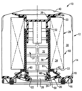
[0012] A filter 10
is shown in Figure 1 and is representative of a typical spin-on
oil filter. The filter 10 includes a housing 12 having a can 14 that provides
a cavity. A
retainer 16 is secured to the can 14 to retain a tapping plate 18. The tapping
plate 18 includes
an inlet 20 provided by multiple apertures 24 arranged circumferentially about
an outlet 2.2.
The outlet 22 is provided by a threaded hole 26 that is used to secure the
filter 10 to a
mounting block (not shown).
[0013] A media pack
28 is arranged within the housing 12 to filter debris from the
oil. Oil flows into the housing 12 through the inlet 20 to an inlet side 30 of
the media pack
28. Oil passes through the media pack 28 and exits to an outlet side 32 and
flows through the
outlet 22.
[0014] The media
pack 28 includes a filter media 34 for debris removal. The
filter media 34 can be arranged between two end caps in a known manner (not
shown).
3
CA 02584587 2007-04-12
ji
Express Mailing# EV236940924US Docket No.
67,277-2652 PUS1
IP06-002
Alternatively, the media pack 28 may be provided using the filter media 34
arranged in a
pocket-pleated arrangement, shown in Figure 2. The filter media 34 includes
pleats 25
arranged in pockets, as is known in the art. The pleats 25 are by secured
beads of adhesive
31 near each of opposing ends 33, to form the pockets, so that the inner edges
29 are in close
proximity to one another. The inner edges 29 provide a central opening 35 that
extends
between the ends 33. Using a filter media 34 of the type shown in Figure 2
permits the
elimination of end caps that are typically secured to the ends 33. Instead,
flexible seals are
arranged at the ends 33 and extend to the inner edges 29 to ensure that oil
flows from the inlet
side 30 to the outlet side 32 without bypassing the filter media 34.
[0015] Returning to
Figure 1, a center tube 36 is arranged within the central
opening 35 (Figure 2) to support the inner edges 29 so that the filter media
34 does not
collapse inwardly under oil pressure. The center tube 36 is a unitary
structure in the example
shown and includes openings 37 that permit oil to flow through the center tube
36. A guide
38 is secured to the center tube 36. The guide 38 engages a wall 40 of the
housing 12 to
position and load the components within the filter 10 as desired. To seal the
filter media 34, a
seal 44 is provided between the filter media 34 and the guide 38. An anti-
drainback valve 42
is arranged between the other end 33 and the center tube 36 to provide a seal.
In this manner,
an additional gasket or seal is not needed to seal the end of media pack 28
near the tapping
plate 18. A relief valve 46 is supported by a first end 50 of the center tube
36 while an
opposing second end 52 of the center tube is used to secure the guide 38 with
an interlocking
connection, in the example shown. The anti-drainback valve 42, seal 44 and
relief valve 46
are constructed from suitable materials, such as elastomers, to provide an
adequate seal
between the adjacent components.
4
CA 02584587 2007-04-12
-
Express Mailing# EV236940924US Docket No.
67,277-2652 PUS1
IP06-002
[0016] Referring to
Figure 3, the relief valve 46 includes a base 54 from which
outer and inner legs 56 and 58 extend. A groove is arranged between the outer
and inner legs
56 and 58 to provide a J-shaped cross-section. The inner leg 58 includes a lip
60 that engages
an inner surface 61 of the center tube 36. The inner leg 58 blocks openings 48
in the center
tube 36 when the relief valve 46 is in the closed position, which is shown.
The lip 60 is
spaced from the inner surface 61 in the open position, shown in phantom in
Figure 3. The
inner leg 58 is arranged at the interior of the center tube 36 so as not to
interfere with the
operation of the anti-drainback valve 42. The open relief valve 46 permits oil
to flow directly
from the inlet 20 through the openings 48 and out the outlet 22. The relief
valve 46 moves to
the open position under high oil pressure conditions, or when the filter media
34 has become
clogged, to bypass the filter media 34.
[0017] The center
tube 36 includes a seat 64 that extends outwardly from the
center tube 36. The anti-drainback valve 42 includes an annular flange 66 that
is supported
on the seat 64 and acts as a seal between the center tube 36 and the end 33.
An intermediate
portion 68 extends radially outward and toward the tapping plate 18 (Figure 1)
to an annular
lip 70 that is in sealing engagement with the tapping plate 18 when the anti-
drainback valve
42 is in a closed position. The intermediate portion 68 and annular lip 70 are
arranged
radially outwardly of the inner leg 58 so as not to interfere with the
operation of the relief
valve 46. The anti-drainback valve 42 is shown in the open position by the
phantom line in
Figure 1 and disengaged from the tapping plate 18. The anti-drainback valve 42
is in the
open position (phantom in Figure 1) during normal operating conditions to
permit oil to flow
into the filter 10. The anti-drainback valve 42 closes to prevent debris from
the dirty side of
the filter media 34 from draining back to the engine when it is not running.
CA 02584587 2007-04-12
-
Express Mailing# EV236940924US Docket No.
67,277-2652 PUS1
1P06-002
[0018] Referring to
Figure 1, the media pack 28, center tube 36, guide 38, seal 44
and anti-drainback valve 42 provide a filter cartridge assembly 82. The relief
valve 46 acts as
a seal between the filter cartridge assembly 82 and the tapping plate 18.
[0019] The filter
10 is relatively easy to assemble compared to prior art filter
arrangements. First, the anti-drainback valve 42 is installed onto the center
tube 36 so that
the annular flange 66 is supported on the seat 64. Alternatively, the anti-
drainback valve 42
can be over molded onto the center tube 36. The second end 52 of the center
tube 36 is
inserted into the central opening 35 of the media pack 28. The seal 44 is
installed onto the
guide 38. The seal 44 may also be glued to the guide 38 or over molded onto
it. The guide
38 is secured to the center tube 36 using the interlocking connection. The
center tube 36 and
guide 38 are loaded so that the anti-drainback valve 42 and seal 44 are in
good sealing
engagement with the opposing ends 33 of the media pack 28.
[0020] The relief
valve 46 is installed onto the filter cartridge assembly 82 so that
the first end 50 is seated in the groove of the relief valve 46. The filter
cartridge assembly 82
is then inserted into the cavity provided by the can 14. The tapping plate 18
is secured to the
can 14 using the retainer 16, as is well known in the art. The base 54 of the
relief valve 46
seals against the tapping plate 18.
[0021] Although a
preferred embodiment of this invention has been disclosed, a
worker of ordinary skill in this art would recognize that certain
modifications would come
within the scope of this invention. For that reason, the following claims
should be studied to
determine the true scope and content of this invention.
6