Note: Descriptions are shown in the official language in which they were submitted.
CA 02584735 2007-04-19
WO 2006/047232
PCT/US2005/037783
POLARIZATION-SENSITIVE VISION PROSTHESIS
FIELD OF INVENTION
This invention relates to a vision prosthesis, and in particular, to dynamic
control
of optical characteristics of a vision prosthesis.
BACKGROUND
In the course of daily life, one typically regards objects located at
different
distances from the eye. To selectively focus on such objects, the focal length
of the eye's
lens must change. In a healthy eye, this is achieved through the contraction
of a ciliary
muscle that is mechanically coupled to the lens. To the extent that the
ciliary muscle
contracts, it deforms the lens. This deformation changes the focal length of
the lens. By
selectively deforming the lens in this manner, it becomes possible to focus on
objects that
are at different distances from the eye. This process of selectively focusing
on objects at
different distances is referred to as "accommodation".
As a person ages, the lens loses plasticity. As a result, it becomes
increasingly
difficult to deform the lens sufficiently to focus on objects at different
distances. To
compensate for this loss of function, it is necessary to provide different
optical
corrections for focusing on objects at different distances.
One approach to applying different optical corrections is to carry different
pairs of
glasses and to swap glasses as the need arises. For example, one niight carry
reading
glasses for reading and a separate pair of distance glasses for driving. This
is
inconvenient both because of the need to carry more than one pair of glasses
and because
of the need to swap glasses frequently.
Bifocal lenses assist accommodation by integrating two different optical
corrections onto the same lens. The lower part of the lens is pound to provide
a
correction suitable for reading or other close-up work while the remainder of
the lens is
ground to provide a correction for distance vision. To regard an object, a
wearer of a
bifocal lens need only maneuver the head so that rays extending between the
object-of-
regard and the pupil pass through that portion of the bifocal lens having an
optical
1
CA 02584735 2012-09-10
60412-3779
correction appropriate for the range to that object.
The concept of a bifocal lens, in which different optical corrections are
integrated
into the same lens, has been generalized to include trifocal lenses, in which
three different
optical corrections are integrated into the same lens, and continuous gradient
lenses in
which a continuum of optical corrections are integrated into the same lens.
However, just
as in the case of bifocal lenses, optical correction for different ranges of
distance using
these multifocal lenses relies extensively on relative motion between the
pupil and the
lens.
Once a lens is implanted in the eye, the lens and the pupil move together as a
unit.
Thus, no matter how the patient's head is tilted, rays extending between the
object-of-
regard and the pupil cannot be made to pass through a selected portion of the
implanted
lens. As a result, multifocal lenses are generally unsuitable for intraocular
implantation
because once the lens is implanted into the eye, there can be no longer be
relative motion
between the lens and the pupil.
A lens suitable for intraocular implantation is therefore generally restricted
to
being a single focus lens. Such a lens can provide optical correction for only
a single
range of distances. A. patient who has had such a lens implanted into the eye
must
therefore continue to wear glasses to provide optical corrections for those
distances that
are not accommodated by the intraocular lens.
SUMMARY
A vision prosthesis according to one embodiment includes an auto-focus
mechanism
that relies on the difference between the birefringent properties of the
fovea, and the
birefringent properties of portions of the retina surrounding the fovea,
referred to herein
as the "circumfovea." By illuminating the retina with polarized light, and
measuring the
polarization state of light reflected from the retina, it is possible to
estimate how much of
the reflected light was reflected by the fovea and how much was reflected by
the
circumfovea. On the basis of this estimate, a controller causes a change in an
optical
property of an optical system. This, in turn cause a desired change in the
estimate.
2
CA 02584735 2007-04-19
WO 2006/047232
PCT/US2005/037783
In one aspect, the vision prosthesis includes a first detector disposed to
detect a
polarization state of light reflected from a retina; and a controller in
communication with
the first detector. The controller is configured to receive, from the
detector, a
measurement signal indicative of the polarization state, In response, the
controller
generates a control signal for causing a change to an optical property of an
optical system
in optical communication with the retina.
Some embodiments also include a first polarizer in optical communication with
the retina. The first polarizer blocks passage of light having a first
polarization state. The
first polarizer can include, for example, a first polarizing region of a lens
in the optical
element.
Embodiments that include a first polarizer optionally include a second
detector
disposed to detect light passing through the first polarizer. The second
detector is
configured to provide, to the controller, a signal representative of light
passing through
the first polarizer.
Embodiments that include a first polarizer can also include a second polarizer
in
optical communication with the retina. The second polarizer blocks passage of
light
having a second polarization state orthogonal to the first polarization state.
In some embodiments, the first detector in configured to be implanted in a
cornea.
Other embodiments of the vision prosthesis also include those in which the
optical
system includes an intra-ocular lens, a contact lens, an eyeglass lens, or a
natural lens of
the eye.
The controller can be configured to generate a control signal at least in part
on the
basis of a comparison between polarized light reflect from a foveal region of
the retina
and polarized light reflected from elsewhere on the retina. However, the
controller can
also be one that is configured to generate a control signal on the basis of a
comparison
between the polarization state as detected by the first detector and a
polarization state
associated with light reflected from a fovea of the retina. Or, the controller
can be one
3
CA 02584735 2007-04-19
WO 2006/047232
PCT/US2005/037783
that is configured to generate a control signal to cause a change to a focal
length of the
optical system.
In another aspect, the invention includes a vision prosthesis having a
controller
configured to cause an optical property of an optical element to change in
response to a
signal indicative of a polarization state of light reflected from a retina.
Another aspect of the invention includes a method for controlling a vision
prosthesis by detecting a polarization state of light reflected from a retina
and receiving a
measurement signal indicative of the polarization state. In response to the
signal, a
control signal causes a change to an optical property of an optical system in
optical
communication with the retina.
In some practices, generating a control signal includes comparing polarized
light
reflected from a foveal region of the retina and polarized light reflected
from elsewhere
on the retina. The control signal is generated at least in part on the basis
of the
comparison.
In other practices, generating a control signal includes generating a control
signal
at least in part on the basis of a polarization state associated with light
reflected from a
fovea of the retina.
The method can also include causing a change to a focal length of the optical
system in response to the control signal.
Unless otherwise defined, all technical and scientific terms used herein have
the
same meaning as commonly understood by one of ordinary skill in the art to
which this
invention belongs. Although methods and materials similar or equivalent to
those
described herein can be used in the practice or testing of the present
invention, suitable
methods and materials are described below. All publications, patent
applications, patents,
and other references mentioned herein are incorporated by reference in their
entirety. In
case of conflict, the present specification, including definitions, will
control. In addition,
the materials, methods, and examples are illustrative only and not intended to
be limiting.
4
CA 02584735 2007-04-19
WO 2006/047232
PCT/US2005/037783
Other features and advantages of the invention will be apparent from the
following detailed description, and from the claims.
BRIEF DESCRIPTION OF THE DRAWINGS
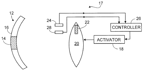
FIG. 1 shows a lens focusing light on the fovea;
FIG. 2 shows a lens focusing light anterior to the fovea;
FIG. 3 shows an embodiment of a vision prosthesis with two detectors and one
polarizing region;
FIG. 4 illustrates resolution of polarization vectors;
FIG. 5 shows an embodiment of a vision prosthesis with two polarizing regions
and
one detector; and
FIG. 6 is an embodiment in which polarization is provided by the cornea.
DETAILED DESCRIPTION
FIG. 1 shows polarized light entering a lens 10 and being focused onto a
retina
12, and in particular, onto the fovea 14 of the retina. The polarized light is
characterized
by an incident polarization state P1. In the process of being reflected by the
fovea 14, the
incident light has its polarization state changed. The foveally-refl ected
light thus has a
reflected polarization state, PF, that differs from the incident polarization
state, P1. The
extent of this difference corresponds to the birefringent properties of the
fovea 14.
FIG. 2 shows polarized light entering a lens 10 that fails to focus onto the
fovea
14. In this particular example, the lens 10 brings light to a focus anterior
to the retina 12.
However, the same principle is at work when the lens 10 brings light to a
focus posterior
to the retina 12. In both cases, polarized light illuminates both the fovea 14
and the
circumfovea 16. The reflected light is therefore a combination of foveally-
reflected light,
which is characterized by a first polarization state PF, and circurrifoveally-
reflected light,
which is characterized by a second polarization state PcF. As a result, the
reflected light
acquires a net polarization state that depends in part on the relative
contributions of the
foveal reflection and the circumfoveal reflection.
CA 02584735 2012-09-10
60412-3779
The difference between the polarization state of the reflected light in FIG. 1
and
the polarization state of reflected light in FIG. 2 provides a way to
determine whether the
lens 10 is correctly focusing light on the fovea 14. 'When the lens 10 is in
focus, the
reflection is dominated by foveally-reflected light. Thus, to the extent light
reflected from
the retina 12 has a polarization state consistent with foveally reflected
light, the lens 10 is
in focus.
In the block diagram of FIG. 3, a vision prosthesis 17 includes an actuator 18
for
changing an optical property of an optical system 20. The optical system 20
can include
the natural crystalline lens of the eye, an intraocular lens implanted in the
eye, a contact
lens, or an eyeglass lens. Exemplary lenses include the nematic crystal lenses
described
in U.S. Patent No. 6,638,304, and the deformable and/or translatable lenses
described in
U.S. Application 10/895,504 (now U.S. Patent No. 7,261,736), filed on July 21,
2004.
A variety of actuators can be used in the vision prosthesis 16. These include
the
electrodes described in U.S. patent No. 6,638,304 and the artificial muscle
actuators
described in U.S. Application 10/895,504 (now U.S. Patent No. 7,261,736),
filed on July 21, 2004.
In the vision prosthesis 17 shown in FIG. 3, the lens 20 has a polarizing
region 22
that allows passage only of light having a first polarization state. A first
detector 24 is
disposed to sample light exiting the polarizing region 22. This first detector
24 provides,
to a controller 26, a first signal indicative of the polarization state of
that incoming light.
A second detector 28 is disposed to sample light reflected from the retina 12.
This
second detector 28, provides to the controller 26, a second signal indicative
of the
polarization state of the reflected light. The first and second signals
together provide an
indication of the extent to which reflection from the retina 12 changes the
polarization
state of the polarized light incident thereon.
The controller 26 is calibrated such that the extent to which the fovea 14 by
itself
alters the polarization state of light incident thereon is known. On the basis
of the first
and second signals, and the calibration data, the controller 26 determines the
relative
contributions of the foveal and circumfoveal reflections to the light
reflected from the
6
CA 02584735 2007-04-19
WO 2006/047232
PCT/US2005/037783
retina 12. The controller 26 then generates a signal for causing the actuator
18 to change
the focal length of the lens 20 so as to cause the foveal contribution to
increase at the
expense of the circumfoveal contribution.
FIG. 4 illustrates one way in which the controller 26 can determine the
relative
contributions of the foveal and circumfoveal reflections. A first polarization
vector P1 in
FIG. 4 represents the polarization state of light incident on the retina 12,
and a second
polarization vector PF represents the polarization state of the foveal
reflection. A third
polarization vector Pm corresponds to the measurement provided by the
detector. This
third polarization vector 13N4 represents the combined effect of both the
foveal and
cicumfoveal contributions to the reflection. It will be apparent that the
foveal contribution
is the projection of the third vector Pm on the second vector PF and that the
circumfoveal
contribution is the remainder thereof.
In many cases, it will not be possible to determine in which direction the
focal
point should be moved. This is because it is not possible to determine, on the
basis of the
relative contributions of the foveal and circumfoveal contributions, whether
the focal
plane is anterior or posterior to the retina 12.
A person who attempts to focus a pair of binoculars encounters a similar
problem.
On seeing a blurry image, it is not apparent which way one must turn the
focusing knob
to bring the image into focus. Most people overcome this difficulty by turning
the
focusing knob in one direction and seeing if the image becomes more blurry,
and then
turning it in the opposite direction if it does so. Similarly, the controller
26 sends a signal
to the actuator 18 to move the focal plane in on_e direction and observes the
change in the
relative contributions of the foveal and circumfoveal reflections. If the
circumfoveal
contribution increases at the expense of the foveal contribution, the
controller 26 corrects
itself by sending a signal to move the focal plane in the opposite direction.
Another embodiment of a vision prosthesis 30, shown in FIG. 5, features a lens
32
having first and second polarizing regions 36, 34 that impose orthogonal
polarization
states on incident light. For example, in one embodiment, the first polarizing
region 36
passes only light polarized in a first direction and the second polarizing
region 34 passes
7
CA 02584735 2007-04-19
WO 2006/047232
PCT/US2005/037783
only light polarized in a second direction orthogonal to the first direction.
Consequently,
light exiting the second polarizing region 34 represents the polarizing effect
of the retinal
reflection, but with the polarizing effect of the first polarizing region 36
already removed.
This light is then provided to a detector 38. On the basis of the detected
light, the
controller provides a signal to a controller 40. The controller 40 uses this
signal to
generate a control signal to cause an actuator 42 to adjust the focal length
of the lens.
It is known that, to some extent, the cornea itself polarizes light. Another
embodiment, shown in FIG. 6, takes advantage of this corneal polarization. In
this
embodiment, a first detector 44 is disposed to receive light passing through a
cornea 46
and a second detector 48 is disposed to receive light reflected from the
retina 12. Outputs
of the detectors 44, 48 are then processed by a controller 50, which provides
a control
signal to an actuator 52 in the manner discussed in connection with FIG. 1.
Certain embodiments discussed above feature first and second detectors. In
those
embodiments, the functions of those detectors can be integrated into a single
device.
In certain of the foregoing embodiments, one or more polarizing regions are
integral with the lens. However, this need not be the case. The polarizing
regions may be
provided by discrete elements positioned in the optical path of the lens or a
portion
thereof. For example, the polarizing regions may be integrated into a flat
plate that
otherwise has no optical effect.
The foregoing description uses the terrn "lens" to refer to assemblies that
may
include one or more optical elements that cooperate to focus incident light.
The term
"lens" is not to be construed as necessarily being limited to a single
refractive element.
At least some of the embodiments described herein can be used in conjunction
with an inatraocular lens, a contact lens, or an eyeglass lens.
Although the foregoing embodiments are shown with a single detector for
sampling a light wave, it will be appreciated that several detectors can be
provided for
sampling a light wave at several locations on the lens.
8
CA 02584735 2007-04-19
WO 2006/047232
PCT/US2005/037783
It is to be understood that while the invention has been described in
conjunction
with the detailed description thereof, the foregoing description is intended
to illustrate
and not limit the scope of the invention, which is defined by the scope of the
appended
claims. Other aspects, advantages, and modifications are within the scope of
the
following claims.
Having described the invention, and a preferred embodiment thereof, what I
claim
as new, and secured by letters patent is:
9