Note: Descriptions are shown in the official language in which they were submitted.
CA 02584863 2007-04-20
WO 2006/050602 PCT/CA2005/001710
1
METHOD AND APPARATUS FOR THE REDUCTION OF SPURIOUS EFFECTS
ON PHYSIOLOGICAL MEASUREMENTS
TECHNICAL FIELD
[0001] The present invention relates to a method and apparatus for the
reduction of spurious effects on physiological measurements. More
specifically,
the present invention relates to a method and apparatus for the reduction of
motion artifact and spurious noise effects on physiological measurements.
BACKGROUND
[0002] There is a great potential for applying optical technologies to
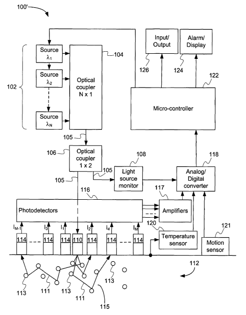
biology,
medicine and sports to track various physiological parameters or states and
provide real time information to the user or to medical personnel. While many
studies have shown this great potential, very few concrete products using
optical
technologies have been developed or marketed. Some of the reasons for this are
the difficulty to isolate a signal of interest from the various interferences
that come
from the external environment, the fact that the measurements must be made in
a
continuous manner on a constantly moving subject and to the variable nature of
the human body itself.
[0003] The elastic nature of human tissue complicates the taking of optical
measurements when a subject is in motion since tissue compression and
expansion instantly affect the optical properties of the tissue while the
signal of
interest remains fairiy constant.
[0004] A complication that comes with the use of portable measurement
devices is that the nature and the sources of the noises are constantly
changing.
Noise sources are present in both the measurement device itself and the
external
environment. Electrical noises from AC lines or surrounding electronic devices
are
obvious noise sources. Optical noise coming from the sun or from artificial
lights
CA 02584863 2007-04-20
WO 2006/050602 PCT/CA2005/001710
2
may migrate into the skin and through the optical sensors. Both the electric
and
the optical noises may vary over time and with the motion of the subject.
[0005] In the present specification, there is described a method and apparatus
designed to overcome the above-described limitations.
SUMMARY
[0006] The present invention relates to a method for reducing motion
artifact when computing estimates of values representative of at least one
physiological parameter of a subject, comprising the steps of measuring a
motion
value and comparing the motion value with a motion threshold. If the compared
motion value is lower than the motion threshold then taking at least one
physiological measurement, estimating the values representative of the at
least
one physiological parameter by applying a mathematical model to the at least
one
physiological measurement and providing the estimate of the values
representative of the at least one physiological parameter.
[0007] The present invention also relates to a method for reducing
motion artifact when computing estimates of values representative of at least
one
physiological parameter of a subject, comprising the steps of repeatably
measuring a motion value and comparing each motion value with a motion
threshold. If the compared motion value is lower than the motion threshold
then
taking at least one physiological measurement, estimating the values
representative of the at least one physiological parameter by applying a
mathematical model to the at least one physiological measurement and providing
the estimates of the values representative of the at least one physiological
parameter. If not, after a predetermined number of consecutive compared motion
values that are higher than the motion threshold then providing a warning to
the
subject.
[0008] The present invention further relates to a method for reducing
motion artifact when computing estimates of values representative of at least
one
CA 02584863 2007-04-20
WO 2006/050602 PCT/CA2005/001710
3
physiological parameter of a subject, comprising the steps of measuring a
motion
value, taking at least one physiological measurement, applying a correction
function to the at least one physiological measurement, the correction
function
being based on the measured motion value, estimating the values representative
of the at least one physiological parameter by applying a mathematical model
to
the at least one corrected physiological measurement and providing the
estimates
of the values representative of the at least one physiological parameter.
[0009] The present invention further still relates to a method for
reducing spurious noise when computing estimates of values representative of
at
least one physiological parameter of a subject, comprising the steps of
generating
a probing signal comprising at least one wavelength, propagating the probing
signal from a propagation point, measuring reflectance values of the probing
signal
for a subset of the at least one wavelength from at least two distances from
the
propagation point, shutting off the probing signal for the subset of the at
least one
wavelength, measuring a shut-off reflectance value from the at least two
distances
from the propagation point, computing adjusted reflectance values by
subtracting
the shut-off reflectance values from the reflectance values, estimating the
values
representative of the at least one physiological parameter by applying a
mathematical model to adjusted reflectance values and providing the estimates
of
the values representative of the at least one physiological parameter.
[0010] The present invention also relates to an apparatus implementing
the above described methods.
[0011] The foregoing and other objects, advantages and features of the
present invention will become more apparent upon reading of the following non
restrictive description of illustrative embodiments thereof, given by way of
examples only with reference to the accompanying drawings.
BRIEF DESCRIPTION OF THE FIGURES
[0012] Non-limitative illustrative embodiments of the invention will now
CA 02584863 2007-04-20
WO 2006/050602 PCT/CA2005/001710
4
be described by way of examples only with reference to the accompanying
drawings, in which:
[0013] Figure 1 which is labeled "Prior Art", is a block diagram showing
an apparatus for the monitoring of skin parameters;
[0014] Figure 2 is a block diagram showing an apparatus for the
monitoring of skin parameters similar to Figure 1 but with a motion sensor;
[0015] Figure 3 is a flow diagram of an algorithm for the monitoring of
skin parameters;
[0016] Figure 4 is a flow diagram of an algorithm for the monitoring of
skin parameters with motion artifact reduction;
[0017] Figure 5 is a flow diagram of an algorithm for setting a motion
threshold;
[0018] Figure 6 is a flow diagram of an alternative algorithm for the
monitoring of skin parameters with motion artifact reduction;
[0019] Figure 7 is a flow diagram of an algorithm for setting a motion
correction factor;
[0020] Figure 8 is a flow diagram of an algorithm for the monitoring of
skin parameters with spurious noise reduction;
[0021] Figure 9 is a flow diagram of an algorithm for the monitoring of
skin parameters with motion artifact reduction and spurious noise reduction;
[0022] Figure 10 shows integrating amplifier waveforms; and
[0023] Figure 11 shows transimpedance amplifier waveforms.
DETAILED DESCRIPTION
CA 02584863 2007-04-20
WO 2006/050602 PCT/CA2005/001710
[0024] Generally stated, a method and apparatus according to an
illustrative embodiment of the present invention provide means to reduce the
adverse effects of environmental conditions such as motion artifact and
spurious
noise effects on physiological measurements used to compute estimates of
physiological parameters, for example skin parameters.
[0025] Referring to Figure 1, an example of a monitoring apparatus 100
estimates skin parameters such as, for example, chromophore concentrations and
scattering coefficient is illustrated. The monitoring apparatus 100 uses N
light
sources (or emitters) 102, each generating a light beam at respective
predetermined wavelengths X, to XN, coupled to a N x 1 optical coupler 104 in
order to generate a probing light beam 105 comprising all of the N wavelengths
of
the N individual light sources 102. The number of light sources 102, and thus
wavelengths, as well as their power levels, may vary depending on the
application.
[0026] The probing light beam 105 then goes through a 1 x 2 optical
coupler 106 that provides the probing light beam 105 to both a light source
monitor
108 and to an emitter collimating optic 110. The emitter collimating optic
110,
advantageously positioned in direct contact with the skin, propagates the
probing
light beam 105 into the dermis 112 of the skin. The probing light beam 105 is
then
attenuated and scattered into a number of reflected beams 111 by various
scatterers 113 and chromophores 115, which are present in the dermis. The
attenuated and reflected beams 111 are then received by receiver collimating
optics 114, providing optical signals I1 to IM to photodetectors 116. Each of
the
receiver collimating optics 114 is positioned at a distance away from the
emitter
collimating optic 110 that is different from that of the other receiver
collimating
optics 114. The number of receiver collimating optics 114 may vary according
to
the application. A temperature sensor 120 provides a signal indicative of the
temperature of the skin.
[0027] An Analog to Digital Converter (ADC) 118 then converts the
analog signals from the light source monitor 108, the photodetectors 116, as
CA 02584863 2007-04-20
WO 2006/050602 PCT/CA2005/001710
6
amplified by amplifiers 117, and the temperature sensor 120 into digital
signals
which are provided to a micro-controller 122. The micro-controller 122
includes an
algorithm that controls the operations of the apparatus and performs the
monitoring of certain clinical states, and may also perform estimations of
certain
biological or physiological parameters such as, for example, chromophore
concentrations and scattering coefficient, which will be further described
below.
The results of the monitoring and estimations are then given to the wearer of
the
monitoring apparatus 100 by either setting a visual, audio and/or mechanical
alarm, when a certain clinical state is detected, of displaying the result via
alarm/display 124. The micro-controller 122 may also be connected to an
input/output 126 through which data such as, for example, a reference blood
glucose level may be provided to the monitoring apparatus 100 or through which
data such as, for example, chromophore concentrations and scattering
coefficient
may be provided from the monitoring apparatus 100 to other devices. It is to
be
understood that the input/output 126 may be any type of interface such as, for
example, an electrical, infrared (IR) or a radio frequency (RF) interface.
[0028] An example of an algorithm that may be executed by the micro-
controller 122 is depicted by the flow chart shown in Figure 3. The steps
composing the algorithm are indicated by blocks 206 to 220.
[0029] At block 206 the algorithm starts by propagating light comprising
one or more wavelengths into the skin, the wavelengths being selected
according
to the application of interest such that variations on light reflectance
values at the
input of the receiver collimating optics 114 may be observed as a function the
variation of some estimated parameters.
[0030] At block 208, the diffuse light reflectance is measured at two or
more distances from the source of the propagated light of block 206. The
diffuse
light reflectance measurements are advantageously taken simultaneously for all
distances, the longer the time interval between each measurement, the less
precise the algorithm results may become. The distances, as well as their
values,
CA 02584863 2007-04-20
WO 2006/050602 PCT/CA2005/001710
7
are selected according to the application. The more distances are used, the
more
precise the diffuse light reflectance model becomes, but also the more
computation intensive it becomes and more expensive becomes the associated
estimation apparatus 100.
[0031] At block 214, which is optional, the skin temperature is
measured.
[0032] Then, at block 216, the algorithm computes estimates of the
desired physiological parameters using the reflectance measurements, and skin
temperature if measured, and displays those estimates at block 218 using
display/alarm 124. The algorithm may further detect clinical conditions using
the
estimated parameter values, in which case block 218 may also activate an alarm
using display/alarm 124. It is to be noted that the parameter estimates and/or
detection of clinical conditions may also be provided to another device for
further
processing using input/output 126. Following which, at block 220, the whole
algorithm is repeated if continuous monitoring is desired, otherwise the
algorithm
ends.
[0033] Various environmental conditions may affect the photodetectors
116 readings of the reflected beams 111 received by receiver collimating
optics
114, which readings are used at block 216 to compute estimates of the desired
physiological parameters. One such condition is movement of the wearer of the
device, which may cause motion artifacts between the apparatus and the skin
and/or the skin and the underlying tissues. A second condition is spurious
noise
present in the reflected beam 111, such as caused by ambient lighting, to
which
possible electrical offsets from the photodetectors 116 or amplifiers 117 may
be
added.
Motion Artifact Reduction
[0034] In order to reduce motion artifact caused by, for example,
relative movement between the skin and the monitoring device 100 or skin
CA 02584863 2007-04-20
WO 2006/050602 PCT/CA2005/001710
8
structure deformation, the monitoring device 100 illustrated in Figure 1 may
be
modified by adding a motion sensor 121 resulting in the monitoring device 100'
illustrated in Figure 2. The motion sensor 121, which may be, for example, an
accelerometer, a pressure sensor or a combination of both and may be
advantageously positioned in contact with the skin. It is to be understood
that in
the case where the motion sensor 121 is, for example, an accelerometer, it may
be
positioned at another location within or on the monitoring device 100'.
[0035] The ADC 118 then converts the analog signals from the motion
sensor 121, into a digital signal which is supplied to the micro-controller
122. The
micro-controller 122 algorithm, which controls the operations of the apparatus
and
performs various computations and estimations according to the applications,
then
takes into account the information provided by the motion sensor 121.
[0036] The algorithm previously depicted by the flow chart shown in
Figure 3 may be modified to take into account this new information resulting
in the
algorithm depicted by the flow chart shown in Figure 4. The steps composing
the
algorithm are indicated by blocks 202 to 220.
[0037] At block 202 the algorithm starts by measuring the motion of the
monitoring device 100'. To that end, many current off the shelf accelerometers
and/or pressure sensors may be used for motion sensor 121. Then, at block 204,
the algorithm verifies if the measured motion is inferior to a preset
threshold value,
if so it goes to block 206 and proceeds as per the previous description of the
algorithm of Figure 3, if not, the algorithm goes back to block 202.
[0038] Alternatively, in case where the wearer of the monitoring
apparatus 100' is in constant movement above the predetermined motion
threshold, a timer or a counter may be added to the algorithm in order to set
an
alarm to warn the wearer to stand still for a certain period of time in order
for the
apparatus to proceed with an estimation of the desired physiological
parameters.
[0039] The value of the threshold used at block 204 may be set
CA 02584863 2007-04-20
WO 2006/050602 PCT/CA2005/001710
9
according to theoretical values or may alternatively be set by the algorithm
depicted by the flow chart shown in Figure 5. The steps composing the
algorithm
are indicated by blocks 302 to 314.
[0040] At block 302 the algorithm starts by computing initial estimates of
the desired physiological parameters using, for example, the algorithm
depicted by
the flow chart shown in Figure 3. At block 304, the algorithm measures the
initial
motion value of the monitoring apparatus 100' and at block 306, sets the
motion
threshold value to that measured initial value.
[0041] Then, at block 308, incremental movement is applied to the
monitoring apparatus 100', following which estimates of the desired
physiological
parameters are computed at block 310 and a new motion value is measured at
block 312.
[0042] The algorithm then compares the current parameters estimates
to the previous estimates in order to determine if there is a significant
difference. If
there is a significant difference then the algorithm terminates and returns
the value
of the motion threshold, if not, the algorithm goes back to block 306 where
the
motion threshold is set to the current motion value and proceeds to repeat
blocks
308 to 314.
[0043] The above described motion artifact reduction technique may be
used with many other types of measurement apparatuses such as, for example,
Oximeters or any other measurement apparatus susceptible to motion.
[0044] An alternative algorithm to the algorithm depicted by the flow
chart shown in Figure 4 is depicted by the flow chart shown in Figure 6. The
steps
composing the algorithm are indicated by blocks 202 to 220.
[0045] At block 202 the algorithm starts by measuring the motion of the
monitoring device 100'. Then, at block 206, the algorithm propagates light
comprising one or more wavelengths into the skin, the wavelengths being
selected
CA 02584863 2007-04-20
WO 2006/050602 PCT/CA2005/001710
according to the application of interest such that variations on light
reflectance
values at the input of the receiver collimating optics 114 may be observed as
a
function the variation of some estimated parameters.
[0046] At block 208, the diffuse light reflectance is measured at two or
more distances from the source of the propagated light of block 206. The
diffuse
light reflectance measurements are advantageously taken simultaneously for all
distances, the longer the time interval between each measurement, the less
precise the algorithm results may become. The distances, as well as their
values,
are selected according to the application. The more distances are used, the
more
precise the diffuse light reflectance model becomes, but also the more
computation intensive it becomes and more expensive becomes the associated
estimation apparatus 100'.
[0047] At block 209 the algorithm applies a motion correction function to
the light reflectance measurements made at block 208. The motion correction
function is based on the measured motion and is applied in order to compensate
for the variation in the measured light reflectance due to the movements of
the
wearer of the monitoring apparatus 100'.
[0048] At block 214, which is optional, the skin temperature is
measured.
[0049] Then, at block 216, the algorithm computes estimates of the
desired physiological parameters, using the corrected reflectance
measurements,
and skin temperature if measured, and displays those estimates at block 218
using
display/alarm 124. The algorithm may further detect clinical conditions using
the
estimated parameter values, in which case block 218 may also activate an alarm
using display/alarm 124. It is to be noted that the parameter estimates and/or
detection of clinical conditions may also be provided to another device for
further
processing using input/output 126. Following which, at block 220, the whole
algorithm is repeated if continuous monitoring is desired, otherwise the
algorithm
CA 02584863 2007-04-20
WO 2006/050602 PCT/CA2005/001710
11
ends.
[0050] The motion correction function used at block 209 may be set
using the algorithm depicted by the flow chart shown in Figure 7. The steps
composing the algorithm are indicated by the blocks 302 to 316.
[0051] At block 302 the algorithm starts by measuring the light
reflectance by propagating light comprising one or more wavelengths into the
skin,
the wavelengths being selected according to the application of interest such
that
variations on light reflectance values at the input of the receiver
collimating optics
114 may be observed as a function the variation of some estimated parameters.
The diffuse light reflectance is measured at two or more distances from the
source
of the propagated light. The diffuse light reflectance measurements are
advantageously taken simultaneously for all distances, the longer the time
interval
between each measurement, the less precise the algorithm results may become.
The distances, as well as their values, are selected according to the
application.
At block 304, the algorithm measures the initial motion value of the
monitoring
apparatus 100' and at block 307, stores the light reflectance measurements as
well as the initial motion value.
[0052] Then, at block 308, incremental movement is applied to the
monitoring apparatus 100', following which light reflectance is measured at
block
310 and a new motion value is measured at block 312.
[0053] The algorithm then compares, at block 314, the measured
motion value to a motion threshold. The motion threshold may be set, for
example, to a value that is superior to any motion value that may be generated
during normal use by a wearer of the monitoring apparatus 100'. If the
measured
motion value is above the motion threshold, then the algorithm goes to block
316
where a motion correction function is computed using the stored light
reflectance
measurements and associated measured motion values and then terminates. If
the measured motion value is not above the motion threshold, the algorithm
goes
CA 02584863 2007-04-20
WO 2006/050602 PCT/CA2005/001710
12
back to block 307 where the current light reflectance measurements and
measured motion value are stored, and proceeds to repeat blocks 308 to 314.
[0054] It should be understood that the computation of the motion
correction function may be done using any suitable numerical analysis method
such as, for example, cubic splines or linear regressions. It should be
further
understood that if, for example, both an accelerometer and a pressure censor
are
used, that the threshold may have two components or a single combined
component. Furthermore, in the case where the threshold has more than one
component, either or all of the measured motion values components may be
required to be above or below each corresponding threshold component.
Spurious Noise Reduction
[0055] The photodetectors 116 converts the optical signal to an
electrical current that will be amplified by amplifiers 117. Two commonly used
amplifier technologies are the integrating amplifier and the transimpedance
amplifier. Figures 10 and 11 show integrating amplifier waveforms and
transimpedance amplifier waveforms, respectively, for a given Xi.
[0056] Referring to Figure 10, when a signal is emitted by the light
sources 102, a first waveform 32 is perceived from the photodetectors 116
using
integrating amplifiers. The waveform 32 comprises signal 36, noise 37 and
electrical offset 38 components. When no signal is emitted by the light
sources
102, a second waveform 34 is perceived from the photodetectors 116, which
waveform 34 comprises noise 37 and electrical offset 38 components. The noise
37 component is due, for example, to external lighting conditions which
diffuse
additional light within the skin and integrated electrical offsets. As for the
electrical
offset 38 component, it is mainly due to charge transfer during the switching
of the
integrator and integrator amplifier voltage offsets.
[0057] As may be observed, the undesired first waveform 32
components, i.e. the noise 37 and the electrical offset 38 components, may be
CA 02584863 2007-04-20
WO 2006/050602 PCT/CA2005/001710
13
measured separately from the signal 36 component by taking measurements when
the light sources 102 are turned off, i.e. when there is no signal 36
component in
the waveform detected by the photodetectors 116.
[0058] The signal 36 component may then be recuperated from the first
waveforms 32 by subtracting the slope 35 of the second waveform 34 from the
slope 33 of the first waveform 32, thus subtracting the noise 37 and the
electrical
offset 38 components. The slopes 33, 35 may be determined using, for example,
least square fitting.
[0059] Similarly for photodetectors 116 using transimpedance
amplifiers, as shown in Figure 11, when a signal is emitted by the light
sources
102, a first waveform 42 is perceived by the photodetectors 116, which
waveform
42 comprises signal 46, noise 47 and electrical offset 48 components. When no
signal is emitted by the light sources 102, a second waveform 44 is perceived
by
the photodetectors 116, which waveform 44 comprises noise 47 and electrical
offset 48 components.
[0060] As may be observed, the undesired first waveform 42
components, i.e. the noise 47 and the electrical offset 48 components, may be
measured separately from the signal 46 component by taking measurements when
the light sources 102 are turned off, i.e. when there is no signal 46
component in
the waveform detected by the photodetectors 116.
[0061] The signal 46 component may then be recuperated from the first
waveforms 42 by subtracting the intensity value 45 of the second waveform 44
from the intensity value 43 of the first waveform 42, thus subtracting the
noise 47
and the electrical offset 48 components.
[0062] The algorithm previously depicted by the flow chart shown in
Figure 3 may be modified in order to reduce spurious noise present in the
reflected
beam 111, and possible electrical offsets from the photodetectors 116,
resulting in
the algorithm depicted by the flow chart shown in Figure 8. The steps
composing
CA 02584863 2007-04-20
WO 2006/050602 PCT/CA2005/001710
14
the algorithm are indicated by blocks 206 to 220.
[0063] At block 206 the algorithm starts by propagating light comprising
one or more wavelengths into the skin, the wavelengths being selected
according
to the application of interest such that variations on light reflectance
values at the
input of the receiver collimating optics 114 may be observed as a function the
variation of some estimated parameters.
[0064] At block 208, the diffuse light reflectance is measured at two or
more distances from the source of the propagated light of block 206. The
diffuse
light reflectance measurements are advantageously taken simultaneously for all
distances, the longer the time interval between each measurement, the less
precise the algorithm results may become. The distances, as well as their
values,
are selected according to the application. The more distances are used, the
more
precise the diffuse light reflectance model becomes, but also the more
computation intensive is becomes and more expensive becomes the associated
estimation apparatus 100.
[0065] At block 210, all light sources are turned off so that no light is
emitted by the monitoring apparatus 100. The algorithm then measures, at block
212, the diffuse light reflectance as per block 208, providing a measurement
of the
spurious noise and possible electrical offsets for each wavelength.
[0066] At block 214, which is optional, the skin temperature is
measured.
[0067] Then, at block 216, the algorithm computes adjusted reflectance
measurement values by subtracting the measurements taken at block 212 from
the measurements taken at block 208, as described above, computes estimates of
the desired physiological parameters using the adjusted reflectance
measurement
values, and skin temperature if measured, and displays those estimates at
block
218 using display/alarm 124. The algorithm may further detect clinical
conditions
using the estimated parameter values, in which case block 118 may also
activate
CA 02584863 2007-04-20
WO 2006/050602 PCT/CA2005/001710
an alarm using display/alarm 124. It is to be noted that the parameter
estimates
and/or detection of clinical conditions may also be provided to another device
for
further processing using input/output 126. Following which, at block 220, the
whole algorithm is repeated if continuous monitoring is desired, otherwise the
algorithm ends.
[0068] It should be noted that the time during which the diffuse light
reflectance is measured, with either the light sources 102 emitting or off,
should be
kept as small as possible so that the spurious ambient light may not vary
substantially between the measurement with the light sources 102 emitting and
off.
[0069] The above described spurious noise reduction technique may be
used with many other types of measurement apparatuses such as optical
measurement apparatuses, for example fiber optics Optical Loss Test Sets
(OLTS), or Radio Frequency (RF) measurement apparatuses.
Motion Artifact Reduction and Spurious Noise Reduction
[0070] Furthermore, both of the above-described techniques may be
combined into a single algorithm depicted by the flow chart shown in Figure 9.
The steps composing the algorithm are indicated by blocks 202 to 220, all of
which
have been previously described in detail.
[0071] Further still, it should be noted that the repetition rate of the
samples or the integration period taken for the purpose of the diffuse light
reflectance measurements, for a given wavelength, may be chosen so as to be a
multiple of the frequency of a parasitic signal, such as, for example, AC line
interference. Thus, when the measurements are averaged over a certain number
of periods, the effects of the parasitic signal cancel out. For example, an AC
line
parasitic signal may have a frequency of 60Hz, so the repetition rate or the
integration period of the samples may then be set to 18.75Hz such that when
the
measurements are averaged over five periods, this corresponds to 16 periods at
60Hz. Similarly, averaging the measurements over six periods corresponds to 16
CA 02584863 2007-04-20
WO 2006/050602 PCT/CA2005/001710
16
periods at 50Hz. The two may also be combined such that averaging the
measurements over 30 periods corresponds to 96 periods at 60Hz and 80 periods
at 50Hz, thus canceling out both the 50Hz and 60Hz parasitic signals. Of
course,
the repetition rate or the integration period of the samples may be selected
so as
to cancel parasitic signals at other frequencies.
[0072] Although the present invention has been described by way of
non-limitative illustrative embodiments and examples thereof, it should be
noted
that it will be apparent to persons skilled in the art that modifications may
be
applied to the present illustrative embodiments without departing from the
scope of
the present invention.