Note: Descriptions are shown in the official language in which they were submitted.
CA 02584961 2007-04-20
WO 2006/047146 PCT/US2005/037438
GENERATOR SET EXHAUST PROCESSING SYSTEM AND METHOD
FIELD OF THE INVENTION
1. The present invention relates generally to generator sets and, more
particularly, to an exhaust possessing system for generator sets employed
within
watercraft such as pleasure boats.
BACKGROUND OF THE INVENTION
2. Watercraft such as sport boats, cruisers, sailboats, yachts, fishing
boats, jet boats, and the like, commonly employ on-board generator sets (often
referred to as "gensets") to generate electricity for use on the watercraft.
The
gensets typically include an alternator driven by a dedicated internal
combustion
engine. As with all internal combustion engines, the engines of gensets
produce
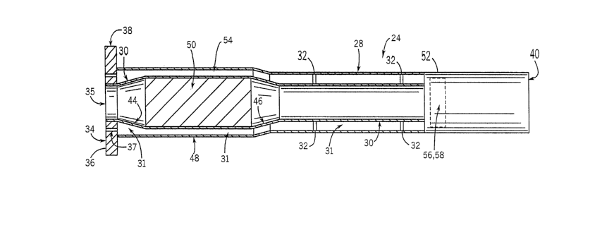
exhaust. This exhaust, if unprocessed, has various components that are
undesirable
for a number of reasons, such as potentially pollutive elements and
undesirable
smells.
3. Despite these undesirable characteristics of exhaust, relatively few
watercraft employ any exhaust-processing devices in conjunction with onboard
gensets to eliminate or reduce the undesirable exhaust components from the
exhaust being expelled into the environment. In fact, with the exception of
watercraft
employing gensets having high-power ratings (e.g., above 25 hp), conventional
watercraft are not mandated by current Environmental Protection Agency (EPA)
requirements to employ any exhaust-processing devices.
4. Further, while some watercraft (particularly larger watercraft that
employ high-power gensets) employ exhaust-processing devices, these devices
are
not readily applicable to smaller watercraft, particularly pleasurecraft
because they
add to the size and cost of the genset and present a relatively hot surface
that
cannot be adeq uately arranged within the confined spaces of smaller
watercraft.
That is, the exhaust emanating from gensets is typically at a high temperature
and
may reach temperatures of up to 1500 degrees F. Accordingly, the eKhaust
created
by an individual genset can rapidly heat up an exhaust-processing device to
present
CA 02584961 2007-04-20
WO 2006/047146 PCT/US2005/037438
an externai surrace inat is extremeiy hot, albeit, not as hot as the exhaust
itself. In
smaller watercraft, however, due to the relatively cramped quarters on the
craft, it is
difficult to arrange a genset and an associated exhaust-processing system so
that
people will not brush up against, or otherwise come into contact with, the
heated
surfaces of the system.
5. It would therefore be desirable to provide a system and method for
processing exhaust produced by a genset disposed on a watercraft. It would be
further desirable to provide a system and method for processing exhaust
produced
by a watercraft genset to reduce undesirable components of the exhaust before
the
exhaust is expelled from the watercraft. It would also be desirable to provide
a
system and method for protecting against contact with heated surfaces of an
exhaust-processing system associated with a genset disposed in a small
watercraft,
where people might come into contact with the exhaust-processing device.
SUMMARY OF THE INVENTION
6. The present invention overcomes the aforementioned drawbacks by
providing a system and method for processing exhaust produced by a watercraft
genset to reduce undesirable components of the exhaust before the exhaust is
expelled from the watercraft. Furthermore, a systern and method protects the
exhaust-processing system from presenting external surfaces with undesirable
temperatures.
7. In accordance with one embodiment, an exhaust processing device for
irnplementation in a marine environment is disclosed. The exhaust processing
device includes an inner tubular structure configured to receive exhaust gases
from
a generator set (genset) and communicate the exhaust gases therethrough. The
exhaust processing device also includes an exhaust processing element mounted
within the iriner tubular structure to process the exhaust gases and an outer
tubular
structure mounted around the inner tubular structure to form an intermediate
space
therebetween. The exhaust processing device further includes at least one
orifice
through which to deliver a flow of water to the intermediate space to maintain
the
outer tubular structure at a temperature below a ternperature of the exhaust
processing element.
-2-
CA 02584961 2007-04-20
WO 2006/047146 PCT/US2005/037438
8. In accordance with another embodiment, a genset assembly for use in
a watercraft is disclosed. The genset assembly includes a genset having an
alternator and an engine with an exhaust manifold. The genset assembly also
includes an exhaust processing device coupled to the exhaust manifold of the
engine. The exhaust processing device further includes an inner conduit to
receive
exhaust from the exhaust manifold at an input end and allow the exhaust to
pass
therefrom to an output end and an exhaust processing element positioned within
the
inner conduit to reduce undesirable exhaust components. Additionally, the
exhaust
processing device includes an outer conduit positioned about the inner conduit
to
define an intermediate space therebetween, wherein upon operation of the
genset, a
temperature of the outer conduit is maintained to be lower than a temperature
of the
inner conduit by a flow of water through the at least one intermediate space.
9. In accordance with yet another embodiment, an exhaust processing
device for implementation in a marine environment is disclosed. The exhaust
processing device includes an inner passage to receive exhaust gases from a
genset and communicate the exhaust gases to an output port. The exhaust
processing device further includes an exhaust processing elernent mounted
within
the inner passage to reduce undesirable components in the exhaust and an outer
wall of the exhaust processing device surrounding the inner passage.
Additionally,
the exhaust processing device includes an insulating passage arranged between
the
exhaust processing element and the outer wall to receive a flow of water
therethrough. Furthermore, the exhaust processing device includes an
insulating
chamber arranged between the exhaust processing element and the outer wall and
having a static insulating medium disposed therein, wherein the insulating
passage
and the insulating chamber work in concert to maintain a tempe rature of the
outer
wall that is substantially reduced from the operating temperature of the
exhaust
processing element.
10. Various other features and advantages of the present invention will be
made apparent from the following detailed description and the d rawings.
-3-
CA 02584961 2007-04-20
WO 2006/047146 PCT/US2005/037438
BRIEF DESCRIPTION OF THE DRAWINGS
11. Fig. 1 is an elevation view of a watercraft having a generator set and
exhaust-processing system in accordance with the present invention;
12. Fig. 2 is an elevation view of the generator set assembly with the
exhaust processing device of Fig. 1, shown in greater detail;
13. Fig. 3 is a cross-sectional view of one arrangement for the exhaust
processing device of Figs. 1-2;
14. Fig. 4 is a cross-sectional view of another arrangement for the exhaust
processing device of Figs. 1-2; and
15. Fig. 5 is a block diagram showing the communication of water through
the generator set system with the exhaust processing device of FIG. 1.
DETAILED DESCRIPTION OF THE PREFERRED EMBODIMENT
16. Referring to Fig. 1, a small watercraft 10 is represented as a
speedboat. The watercraft includes, among other components, a rudder 12 and a
propeller 14 that is driven to propel the boat through the water.
Additionally, as will
be described, the watercraft 10 includes a generator set (or "genset") system
16.
The watercraft 10 could be, for example, a pleasure craft having a length in
the
range of 26 feet to 38 feet. Although shown to be a speedboat, the watercraft
10 is
intended to be representative of a wide variety of different watercraft
including, for
example, sport boats, cruisers, sailboats, yachts, fishing boats, jet boats,
and the like
that employ gensets. In this regard, the present invention is intended to be
applicable to a wide variety of smaller watercraft or other devices that
employ
gensets and that are able to draw upon a source of water.
17. Referring additionally to Fig. 2, the genset system 16 is shown in detail.
The generator set assembly 16 includes a generator set (or "genset") 18 having
an
internal combustion engine 20 and an alternator 22. For example, the genset 18
could be a 5E Marine Generator Set or a 7.3E Marine Generator Set (rated at 5
kW
or 7.3kW, respectively) available from the Kohler Co. of Kohler, Wisconsin.
Additionally, in accordance the present invention, the genset system 16
further
includes an exhaust processing device 24 for processing exhaust created by the
engine 20 of the genset 18 and expelled from an exhaust manifold 26 of the
engine/genset. The exhaust processing device 24 can be, for example,
-4-
CA 02584961 2007-04-20
WO 2006/047146 PCT/US2005/037438
approximately 18 inches long. That is, the relative sizes of the exhaust
processing
device 24 and genset 18 shown in Fig. 2 are not necessarily illustrated to
scale.
18. Referring now to Fig. 3, a cross-sectio nal view of the exhaust
processing device 24 according to one embodiment of the present invention is
shown. As shown, the exhaust processing device 24 includes a first, outer
tubular
structure 28 and a second, inner tubular structure 30. In this regard, the
first, outer
tubular structure 28 is positioned substantially concantrically and coaxially
around
the second, inner tubular structure 30, so as to defir-ie an intermediate
annular space
31 therebetween. As will be described, the intermediate annular space 31 forms
an
insulating passage to isolate the temperature of first, outer tubular
structure 28 from
the temperature of the second, inner tubular structure 30. The two tubular
structures
28, 30 may be held in place relative to one another by way of struts 32 or
similar
structures extending within the intermediate annular space 31.
19. At a first end 34 of the exhaust processing device 24, the device 24 is
configured to interface the exhaust manifold 26 of the generator set 18, as
shown in
Fig. 2. More specifically, the second, inner tubular structure 30 is
configured to mate
with a complementary tubular structure or output port 33 (as shown in Fig. 2)
of the
exhaust manifold 26 so that exhaust is communicated from the output port 33
directly into an inner passage 35 of the tubular structure 30, preferably with
little or
no leakage. In alternate embodiments, the device is configured to receive
exhaust
from a different structure having an exhaust output port, other than an
exhaust
manifold.
20. Referring again to Fig. 3, extending concentrically around and radially
outward from the inner tubular structure 30 at the first end 34 is a mounting
flange or
face 36, which extends, according to one embodiment, beyond the periphery of
the
first, outer tubular structure 28. The mounting face 36 in the present
embodiment
has one or more (e.g., eight) orifices 37 spaced around the mounting face to
form a
passage to the intermediate annular space 31 . Although the orifices 37 shown
in
Fig. 3 extend in an axial direction from the first end 34 axially inward to
the
intermediate annular space 31, it is contemplated that the orifices may extend
from
an outer circumferential surface 38 of the mounting face 36 radially inward to
the
intermediate annular space 31.
21. In either case, the orifices 37 provide a passage for water to be
communicated from the exhaust manifold 26 throug t- the mounting face 36 and
into
-5-
CA 02584961 2007-04-20
WO 2006/047146 PCT/US2005/037438
the intermediate annular space 31 of the exhaust processing device 24. Upon
entering the intermediate annular space 31, the water flows down the length of
the
exhaust processing device 24, from the first end 34 to a second, outlet end
40.
22. Still referring to Fig. 3, the second, inner tubular structure 30 includes
an outwardly tapering section 44 and an inwardly tapering section 46 separated
by
an intermediate large-diameter section 48 within vvhich a catalytic conversion
element 50 (or simply "catalyst") is supported/housed. Therefore, exhaust
entering
the second, inner tubular structure 30 at the first e nd 34 passes through the
outwardly tapering section 44 and into the catalyst 50 within the large-
diameter
section 48, where the exhaust is processed before then passing into the
inwardly
tapering section 46, and then down the remainder of the structure 30 to the
second,
outlet end 40.
23. The catalyst 50 can be any of a variety of catalytic conversion elements
known in the art such as a Platinum/Rhodium catalytic conversion element or
other
element used to reduce vehicle emissions and the like. The catalyst 50 can
perform
any of a number of exhaust processing/cleaning functions such as, for example,
reduction in environmental pollutants or undesirab le gases commonly found in
exhaust (e.g., carbon monoxide). Although the present embodiment employs a
catalytic conversion element as the catalyst 50, alternate forms of exhaust
processing elements known in the art could also be utilized.
24. In operation, exhaust enters the innar tubular structure 30 at a high
temperature (e.g., up to 1500 F). As such, the catalyst 50 is specifically
designed to
operate optimally at these high temperatures. Accordingly, an outer surface 52
of
the exhaust processing device 24 formed by the fi rst tubular structure 28 is
heated
by the operating temperature of the catalyst 50. In this regard, to protect
the outer
surface 52 form reaching these high temperatures, water flows through the
intermediate annular space 31 to perform the dual functionality of cooling and
insulating. Accordingly, the first, outer tubular structure 28 creates a water
jacket
around the catalyst 50 by forming the intermediata annular space 31 as a
passage
through which water flows to maintain a temperature of the outer surface 52,
preferably, such that the outer surface 52 would be comfortable to the touch.
25. Additionally, it is contemplated that t;he water may be forced, under
pressure, through the orifices 37 and into the intermediate annular space 31.
In this
-6-
CA 02584961 2007-04-20
WO 2006/047146 PCT/US2005/037438
i eyara, it is contempiatea tnat ine water is pressurized, for example to 3 to
5 pounds
per square inch (psi), within the intermediate annular space 31.
26. As previously addressed, the catalyst 50 is specifically designed to
operate optimally at the high temperatures associated with the exhaust that it
is
processing. Accordingly, to protect the catalyst 50 from being cooled by the
water
flowing through the intermediate annular space 31, an additional annular space
54
may be formed between the intermediate large-diameter section 48 of the inner
tubular structure 30 and the catalyst 50 to provide insulation. Accordingly,
the
additional annular space 54 forms an insulating chamber that can be filled
with a
static insulating medium. For example, the additional annular space 54 may be
filled
with air. Accordingly, the additional annular space 54 also makes it possible
to
accommodate some expansion/contraction of the catalyst 50 without the
placement
of significant stress upon the inner tubular structure 30. On the other hand,
the
additional annular space 54 may be filled with fiberglass or similar
insulating
substances to provide additional protection against cooling the catalyst 50 as
well as
to protect the outer surface 52 from the operating temperature of the catalyst
50.
27. Therefore, as described above, the intermediate annular space 31
forms an insulating passage through which a liquid coolant flows to act as a
dynamic
insulator between the catalyst 50 and the outer surface 52 of the outer
tubular
structure 28. Additionally, the additional annular space 54 forms an
insulating
chamber that can be filled with a static insulating medium to further insulate
the
catalyst 50 from the outer surface 52 of the outer tubular structure 28, and
vice
versa. Accordingly, the insulating passage and the insulating chamber work in
concert to maintain a temperature of the outer surface 52 that is
substantially
reduced from the operating temperature of the catalyst 50.
28. Additionally, as shown in Fig. 3, the inner tubular structure 30
terminates prior to the second, outlet end 40 formed by the outer tubular
structure
28. Consequently, at a second end 56 of the inner tubular structure 30, the
processed exhaust within the inner tubular structure 30 is mixed with the
water
flowing through the intermediate annular space 31. The mixture of water and
processed exhaust then proceeds to the outlet end 40 of the exhaust processing
device 24 where the mixture is expelled. To prevent the water from backflowing
into
the inner tubular structure 30, a flapper valve 58 may be disposed at the
second end
56. In alternate embodiments, other devices for preventing such backflow could
be
-7-
CA 02584961 2007-04-20
WO 2006/047146 PCT/US2005/037438
used, such as a series of S-turns or other valves. However, if the water is
pressurized within the intermediate annular space 31 , it is contemplated that
the
pressure differential created between the intermediate annular space 31 and
the
exhaust path will render the flapper valve 58 or other backfiow protection
unnecessary.
29. Furthermore, the catalyst 50 is preferably removable and replaceable.
For example, in the embodiment shown in Fig. 3, at least the mounting face 36
and
the outwardly tapering portion 44 of the inner tubular structure 30 are
removable so
that the catalyst 50 can be removed and replaced. kccording to one embodiment,
the intermediate large-diameter section 48 and the inwardly tapering portion
46 in
addition to the aforementioned portions (or even all of these components plus
the
remainder of the tubular structure 30) are removable and, in some cases,
replaceable. On the other hand, it is contemplated that the exhaust processing
system 24 may be removed and replaced, as a whole, as needed.
30. Referring now to Fig. 4, the exhaust processing device 24 may include
a slight bend 59 proximate the second end 56 of the inner tubular structure
30. This
bend 59 is configured so that the general orientation of the portion of the
exhaust
processing device 24 proximate the outlet end 40 is substantially horizontal
when the
exhaust processing device 24 is installed relative to the genset 18 of Fig. 2,
while the
remainder of the conversion device has a generally d ownward slope from the
first
end 34, as shown in Fig. 2. The generally downward slope allows gravity to
assist in
moving the water through the intermediate annular space 31. As illustrated in
the
embodiment shown in Fig. 4, the bend 59 is approximately a 20 degrees bend.
However, it is contemplated that the bend could involve a lesser or greater
degree of
directional change.
31. Referring now to Fig. 5, the general flovv path of water through the
genset system 16 is shown. According to the illustrated embodiment, water is
provided to the exhaust processing device 24 by the genset 18. However, it is
contemplated that the exhaust processing device 24 rnay include its own pump
(not
shown) so as to pull water directly from the water source (i.e. the lake,
river, ocean,
or other waterway through which the watercraft 10 of Fig. 1 travels) to the
exhaust
processing device 24.
32. As shown in Fig. 5, the genset 18 is connected to a water intake 60
that is in fluid communication with a body of water in which the watercraft 10
of Fig. 1
-8-
CA 02584961 2007-04-20
WO 2006/047146 PCT/US2005/037438
is operating. A pump 61 included in the genset 18 pulls water through the
water
intake 60 and pushes it to a fuel cooler 62, a heat exchanger 64, and,
finally, the
exhaust manifold 26 (or to a device adjacent to the exhaust manifold). The
water
then exits the genset 18 through the output port 33 to supply the water to the
exhaust processing device 24. Due to the interaction of the water with the
heat
exchanger 64, the water within the exhaust processing device 24 is somewhat
warmer than it is upon being received by the pump 61. As described above with
respect to Figs. 3 and 4, the water is then passed over the catalyst 50 and
expelled
from the exhaust processing device 24 at the end 40 to return the water to the
body
of water from where it was drawn. On a watercraft such as the watercraft 10 of
Fig.
1, the water may be returned, for example, via a hose that connects the end 40
to an
outlet under a swim platform (not shown) that is, for example, at least 4
inches above
the water line.
33. Also, it is contemplated that one or more sensor devices 66 may be
mounted on the exhaust processing device 24. The sensor devices 66 may be
configured to provide information that is displayed via indicators (not shown)
coupled
to the sensor device 66. Accordingly, the indicators may be positioned on the
exterior of the exhaust processing device 24 or communicate information to
other
devices such as a display near the steering column or the genset 18 (e.g.,
wirelessly
or by way of various connection devices existing between the mounting face 36
and
the exhaust manifold 26). For example, one or more temperature sensors could
be
mounted on the exhaust processing device 24 to indicate the temperatures at
various locations on the device (e.g., at the catalyst 50 or along the outer
surface 52
of the tubular structure 28). Also, for example, a pressure sensor could be
located
within the intermediate annular space 31 that would indicate a blockage of the
flow of
water through that space. Such pressure information could be of value in
preventing
excessive strain on an impeller of the pump 61.
34. Therefore, the above-described invention provides a systern and
method for integrating conventional catalytic conversion elements (or other
exhaust
processing elements) such as those employed on automobiles with gensets used
on
small watercraft for the purpose of processing exhaust gases discharged from
the
gensets. In this regard, the present invention includes a cooling chamber
surrounding an inner exhaust-processing chamber to allow coolant to flovv
about the
exhaust processing chamber and prevent heat from the catalytic conversion
process
-9-
CA 02584961 2007-04-20
WO 2006/047146 PCT/US2005/037438
to excessiveiy raise the temperature of an outer surface of the overall
device.
Additionally, the present invention, in at least some embodiments, provides a
system
and method for the coolant that is directed through the cooling chamber to be
drawn
from the genset itself. Accordingly, the coolant is water that is obtained
from the
body of water within which the watercraft is operating and then returned to
that body
of water after use.
35. While the foregoing illustrates and describes various embodiments of
this invention, it is to be understood that the invention is not limited to
the precise
construction herein disclosed. The invention can be embodied in other specific
forms without departing from the spirit of the invention. For exa mple, the
present
invention is intended to be applicable to a wide variety of water vehicles and
other
(e.g., non-vehicular) devices that employ gensets in proximity to a water
source.
The present invention is also intended to be used with exhaust processing
systems
that employ a variety of different types of catalysts, catalytic conversion
devices, or
other exhaust processing elements.
36. Also, for example, the water provided to the exhaust processing device
need not be provided via the exhaust manifold of a genset as discussed above,
but
rather could be provided via a separate supply line or other mechanism. Also,
in
certain embodiments, more than one catalyst could be used and the tubular
sections
28, 30 could vary from tubes having circular cross-sections to other tubular
structures or other conduits having other shapes (e.g., oval or rectangular
cross-
sections).
37. Therefore, one aspect of the invention includes an exhaust processing
device for implementation in a marine environment. The exhaust processing
device
includes an inner tubular structure configured to receive exhaust gases from a
generator set (genset) and communicate the exhaust gases therethrough. The
exhaust processing device also includes an exhaust processing element mounted
within the inner tubular structure to process the exhaust gases and an outer
tubular
structure mounted around the inner tubular structure to form an intermediate
space
therebetween. The exhaust processing device further includes at least one
orifice
through which to deliver a flow of water to the intermediate space to maintain
the
outer tubular structure at a temperature below a temperature of the exhaust
processing element.
-10-
CA 02584961 2007-04-20
WO 2006/047146 PCT/US2005/037438
36. Hccoraing to anotner aspect of the invention, a genset assembly for
use in a watercraft includes a genset having an alternator and an engine with
an
exhaust manifold. The genset assembly also includes an exhaust processing
device
coupled to the exhaust manifold of the engine. The exhaust processing device
further includes an inner conduit to receive exhaust from the exhaust manifold
at an
input end and allow the exhaust to pass therefrom to an output end and an
exhaust
processing element positioned within the inner conduit to reduce undesirable
exhaust components. Additionally, the exhaust processing device includes an
outer
conduit positioned about the inner conduit to define an intermediate space
therebetween, wherein upon operation of the genset, a temperature of the outer
conduit is maintained to be lower than a temperature of the inner conduit by a
flow of
water through the at least one intermediate space.
39. According to still another aspect of the invention, an exhaust
processing device for implementation in a rnarine environment includes an
inner
passage to receive exhaust gases from a genset and communicate the exhaust
gases to an output port. The exhaust processing device further includes an
exhaust
processing element mounted within the inner passage to reduce undesirable
components in the exhaust and an outer wall of the exhaust processing device
surrounding the inner passage. Additionally, the exhaust processing device
includes
an insulating passage arranged between the exhaust processing element and the
outer wall to receive a flow of water therethrough. Furthermore, the exhaust
processing device includes an insulating chamber arranged between the exhaust
processing element and the outer wall and having a static insulating medium
disposed therein, wherein the insulating passage and the insulating chamber
work in
concert to maintain a temperature of the outer wall that is substantially
reduced from
the operating temperature of the exhaust processing element.
40. The present invention has been described in terms of the preferred
embodiment, and it should be appreciated that many equivalents, alternatives,
variations, and modifications, aside from those expressly stated, are possible
and
within the scope of the invention. Therefore, the invention should not be
limited to a
particular described embodiment. Accordingly, reference should be made to the
following claims, rather than to the foregoing specification, as indicating
the scope of
the invention.
- 11-