Note: Descriptions are shown in the official language in which they were submitted.
CA 02585019 2007-04-23
WO 2006/045196 PCT/CA2005/001649
SNAP-TOP CLOSURE DEVICE
TECHNICAL FIELD
The present invention relates to a closure device
for use on containers, and in particular on disposable
beverage containers.
BACKGROUND ART
In the field of food and beverage packaging,
there is an increasingly high demand for quality
assurance. More specifically, it is very import ant to
provide means for ensuring that the product has not
been tampered with at any stage between the initial
packaging and final consumption by the user. A
variety o f tamper-evident closures have been developed
to meet this need.
The current and most widely used closures for
container s, such as beverage containers, tend to come
completely off from the container when unscrewed and
can be lost before the contents are consumed. Once
lost, re-closure of the partially full container is no
longer possible. Some closures have been developed as
two part closures, with a lower portion that is
connected to both the container and a top sealing
portion, thereby preventing loss of the top port ion.
However, the lower portion, which is fixed to the
container- proximate a mouth of the container, tends to
be cumber some and can get in the way of the conoumers
lips whern the beverage is being consumed.
To provide tamper evidence, closures are often
sealed to the container by a sealing membrane which
must be separately discarded once the container is
CA 02585019 2007-04-23
WO 2006/045196 PCT/CA2005/001649
2
opened. In the case of two part closures, the top
portion is often sealed to the lower portion, the seal
generally being breakable through the action of
opening the container. However, in many cases,
breaking the seal involves holding the lower portion
in place while turning or flipping open the top
portion, making it quite awkward to use. As well,
proximity of the lower portion t the mouth of the
container makes consumption difficult.
US 6,253,937 (Anderson) discloses a two-part
snap-top closure that screws onto the neck of a bottle
opening. There is no disclosure of sealing the lower
portion to the top portion or ro t ating the entire cap
to separate the lower portion fr m the upper portion.
As well, in the reference the tw parts of the closure
are required to snap fit with each other. US
6,530,493 and US Application 2001/0035389 are related
to the Anderson reference.
US 6,234,334 (Suarez) teaches a two part cap
having an arrangement in which t he parts snap to each
other rather than to a lip of the container. This
device completely covers the mouth of the container
and requires that an additional spout means be formed
into the closure.
US 5,755,352 (Wojcik et. al) also teaches that
the two parts of the cap snap to each other and there
is no teaching of rotation of trie lower part to cause
separation from the upper part. The lower part is
engaged to the container neck, so that the upper part
and lower part remain near the m.outh of the container
when the beverage is consumed.
CA 02585019 2007-12-10
3
US 4,856,667 discloses a neck sealing
arrangement, but it does not specifically relate to a
two-part cap.
US 5,813,553 discloses a multiple-part cap but is
principally concerned with a tamper-evident
construction and does not provide means by which the
closure can remain connected to the container, to
prevent loss of the closure.
Finally, British Patent 2,367,802 discloses a
device for carrying a bottle and consists of two parts
that snap-fit together.
It is therefore greatly desired to develop a
closure device for a container that is tamper-evident,
while also connecting the closure to the container and
allowing the closure device to be moved sufficiently
out of the way to allow the users mouth to engage the
container.
DISCLOSURE OF THE INVENTION
The present invention provides a tamper-evident,
re-closable container that comprises a container body,
having a neck portion with a cammed projection, and a
mouth rimmed by a lip and a closure having a top
portion with a groove to rotatably engage and seal
against the lip of the container, and a bottom portion
having a contour formed therein to rest under the
cammed projection. A breakable tamper-evident section
circumferentially connects the top portion of the
closure to the bottom portion of the closure and
connecting means connects the top portion to the
bottom portion. Rotation of the closure around the
mouth of the container causes the cammed projection to
CA 02585019 2007-12-10
4
force the bottom portion downwardly to break the
tamper-evident section.
The present invention also provides a tamper-
evident closure for use with a container having a neck
portion with a cammed projection, and a mouth rimmed by
a lip. The closure comprises a top portion with a
groove to rotatably engage and seal against the lip of
the container and a bottom portion having a contour
formed therein to rest under the cammed projection.
A breakable tamper-evident section circumferentially
connects the top portion of the closure to the bottom
portion of the closure and connecting means connect the
top portion to the bottom portion. Rotation of the top
portion around the mouth of the container causes the
cammed projection to force the bottom portion
downwardly to break the tamper-evident section.
For the purposes of the present invention, the
term "lip" is used to mean a slightly flared or
projecting portion extending from the mouth of the
container.
BRIEF DESCRIPTION OF THE DRAWINGS
A preferred embodiment of the present invention
is described below, in conjunction with the
accompanying figures, wherein:
Fig. 1A is a front perspective view of a preferred
embodiment of the device in a closed position;
Fig. lB is a view equivalent to that of Fig. 1A, but
with a partial cut out;
Fig. 2 is a rear perspective view of the device of
Fig. 1 in a closed position;
CA 02585019 2007-04-23
WO 2006/045196 PCT/CA2005/001649
Fig. 3 is a cross sectional view of the device of the
Fig. 1 in a closed position;
Fig. 4 is a front perspective view of the device of
Fig. 1 in an open position;
5 Fig. 5 is a second front pe rspective view of the
device of Fig. 1 in an open position;
Fig. 6a is a cross-sectiona.l view of an alternative
embodiment of the device of Fig. 1; and
Fig. 6b is a top plan view of an alternative
embodiment of the device of Fig. 1.
BEST MODES FOR CARRYING OUT THE INVENTION
The invention comprise s a one-piece container
closure, having a top portlon designed to snap around
the mouth of a container and that is attached by a
connecting means and a tamper-evident section to a
bottom portion.
To open the container, the user twists the
closure causing separation at the tamper-evident
section, so that the top p rtion can now be snapped
open and remains attached to the bottom portion by the
connecting means. The top portion can be snapped back
onto the container to re-close the container or
alternatively the top portion can be removed from the
container for recycling pu rposes, after consumption of
the contents of the container.
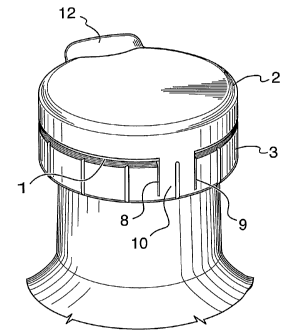
With reference to Fig. 1, a closure is provided,
made of a top portion 2 and a bottom portion 3, which
are initially attached to one another by a breakable,
tamper-evident section 1 that runs circumferentially.
A bead groove 4 is formed in the top portion 2 of the
closure. The bead groove 4 is designed to snap around
CA 02585019 2007-04-23
WO 2006/045196 PCT/CA2005/001649
6
a bead or lip 5 at a mouth of the container.. The
bottom portion 3 of the closure is formed to mate with
a corresponding cammed projection 6 on a neck of the
container. The bottom portion 3 is otherwise
unconnected to the container, and is held in place
just below the mouth of the container only by its
connection to the top portion, through the tamper-
evident section.
The top portion 2 and bottom portion 3 are
connected to one another by connecting means, for
example a hinged section, as illustrated in Fig. 2 . In
this figure, two vertically running slits 8 and 9 are
formed in the bottom portion 3 of the closure to
provide a hinged section 10 that interrupts the
breakable, tamper-e-\aident section 1.
More preferably, a flexible joint 11 in the
bottom portion 3 is shown in Fig. 3 that can run
between slits 8 and 9 and act as a hinge to allow the
top portion 2 to be disengaged from the container, but
remain connected to the bottom portion 3. This is
configuration is shown in Fig. S. The hinged section
10 also includes a breakable section 13 that can be
easily fractured or torn so that the top portion 2 of
the closure can be removed from the container for
recycling purposes.
In an alternate embodiment, a flexible, thin C-
shaped strip can be used to connect the top portion 2
to the bottom portion 3.
An optional thumb lever 12 provides traction for
unsnapping the top portion 2 of the closure from the
container mouth once the tamper-evident section 1 has
been fractured by twisting the closure.
CA 02585019 2007-04-23
WO 2006/045196 PCT/CA2005/001649
7
The c i osure can be applied to the container by a
number of means, and are not limited to those
discussed below, which serve only to illustrate
options for application. In one embodiment, the
closure is formed of two pieces. The first piece
comprises the cam-mating formation and can be placed
on the underside of the cam on the container. The
second piece comprises the bead groove 4 and can be
slid over the lip 5 and the cammed projection 6 and
locked onto the first piece by a one way locking
feature or can be glued to the first piece.
In another embodiment, one-way flexibLe threads
can be formed on the bottom portion 3 of the closure,
which flex outwardly when the closure is pushed onto
the container, to slip over the cammed projection 6.
The thread s then springs back, thereby preventing the
closure from being pulled off without opening the
closed container.
.
Any suitable and well known anti-backi.ng off
measure can be applied to the present invention to
prevent the closure from being removed from the
container without breaking the tamper evidant section
1. In one illustrative example of such anti-backing
off ineasurre, the threads or the cammed projection 6 on
the container have ratcheted surfaces that mate with
opposing ratcheted surface in the closure when the
closure is initially applied to the container. The
mated rat cheted portions prevent the closuxe from
being scrawed off if twisted in an opposite direction.
The device of the present invention operates by
first twisting the closure. As the closure is
twisted, the cammed projection 6 causes the bottom
CA 02585019 2007-04-23
WO 2006/045196 PCT/CA2005/001649
8
portion 3 to move further down towards the base of the
container while the top portion 2 of the closure
remains at a constant level on the mouth of the
contai ner. This action puts a high level of stress on
the tamper-evident section 1, causing it to fracture.
The top portion 2 of the closure can then be unsnapped
from the lip 5 on the mouth of the container, thus
opening the container. In a preferred embodiment, the
thumb lever 12 can then be used for unsnapping the
closure. Since the bottom portion 3 is no t fixed to
the container, the entire closure tends to fall down
the ne ck of the container after opening, as seen in
Fig. 4.
The term "cammed projection" is used throughout
the de scription of the present invention, however it
is to be understood that embodiments such as, for
example, a threaded section encircling the neck of the
container, thread segments, or an undulated sinusoidal
wave form around the neck of the container, are
encompassed by this term. The cammed projection is
formed so that the number of rotations required to
fracture the tamper-evident section 1 is minimized,
and is preferably from l0 to 4 rotations.
The top portion 2, which remains attached to the
bottorn portion 3 by the hinged section 10, can also be
slid down towards the base of the container so that
the mouth of the container is kept free from
obstruction while the contents are being consumed.
The c 1 osure can then be snapped back onto the
conta z.ner, thus re-closing the container if the
contents are not consumed in one sitting_
CA 02585019 2007-04-23
WO 2006/045196 PCT/CA2005/001649
9
Preferably, flutes, ribs or other geometric
features 14 can be added to the bottom portion 3 to
provide a gripping surface between a user's hand and
the closure, to aid in twisting the closure.
In another embodiment, as illustrated in Figs. 6A
and 6B, the optional thumb lever 12 may be shaped to
allow the user to break the tampe r-evident section and
open the closure using one hand. Zn this case, the
container is held in one hand and the thumb of the
same hand is used to push on the thumb lever causing
rotation of the top portion 2 of the closure using the
thumb lever 12. The thumb lever 12 provides a
leverage structure so that a sufficient amount of
force can be comfortably generated by a person to
rotate the closure on the containe r, thus causing the
tamper evident section to break. In further
embodiments (not shown) , the thumb lever can be formed
in the bottom portion 3 of the closure to facilitate
rotation of the closure, or on each of the top portion
2 and the bottom portion 3 to faci.litate both rotation
of the closure and snapping off of the top portion.
In a further embodiment, the bottom portion 3 of
the closure can be formed to mate with a lowermost
thread of any conventional threaded plastic beverage
container. In this embodiment, the top portion 2 of
the closure can be formed to engage the mouth of the
container by, for example, making the inside diameter
of the top portion 2 nominally sma ller than the
outside diameter of the mouth of the container so that
the top portion 2 squeezingly engages the mouth. This
latter embodiment would preferably apply to low
carbonation or non-carbonated beve rage applications.
CA 02585019 2007-04-23
WO 2006/045196 PCT/CA2005/001649
In a further optional ernbodiment, a compound may
be added to the bead groove 4 of the top portion 2 to
ensure a snug mating with the lip 5. This embodiment
is particularly useful in packaging carbonated
5 beverages, in which gas can easily escape from the
container. The addition of a compound acts to fill
any gaps between the lip 5 and the bead groove 4 that
may occur due to surface defects on the bead groove 4
or lip 5 and which could allow for gasses to escape.
10 The compound can be similar to those used in crowns or
plastic closures used on be-~rerage containers. The
actual composition and form of the compound will
depend upon the substance held within the container.
This detailed description of the methods and
products is used to illustra te the prime embodiment of
the present invention. It will be obvious to those
skilled in the art that vari ous modifications can be
made in the present device and that various
alternative embodiments can be utilized. Therefore, it
will be recognized that vari ous modifications can be
made in the products of the present invention and in
the applications to which the products are applied
without departing from the S cope of the invention,
which is limited only by the appended claims.