Language selection

Search

Patent 2585632 Summary

Third-party information liability

Some of the information on this Web page has been provided by external sources. The Government of Canada is not responsible for the accuracy, reliability or currency of the information supplied by external sources. Users wishing to rely upon this information should consult directly with the source of the information. Content provided by external sources is not subject to official languages, privacy and accessibility requirements.

Claims and Abstract availability

Any discrepancies in the text and image of the Claims and Abstract are due to differing posting times. Text of the Claims and Abstract are posted:

  • At the time the application is open to public inspection;
  • At the time of issue of the patent (grant).
(12) Patent Application: (11) CA 2585632
(54) English Title: HAND TOOL
(54) French Title: OUTIL A MAIN
Status: Deemed Abandoned and Beyond the Period of Reinstatement - Pending Response to Notice of Disregarded Communication
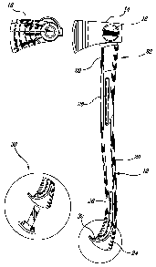
Bibliographic Data
(51) International Patent Classification (IPC):
  • B25G 01/10 (2006.01)
  • B25G 03/34 (2006.01)
  • B26B 23/00 (2006.01)
(72) Inventors :
  • FORTIER, ANDRE (Canada)
  • JULIEN, PATRICK (Canada)
  • LAMARRE, SIMON (Canada)
  • GUAY, MARIE-CLAUDE (Canada)
(73) Owners :
  • GARANT GP
(71) Applicants :
  • GARANT GP (Canada)
(74) Agent: LAVERY, DE BILLY, LLP
(74) Associate agent:
(45) Issued:
(22) Filed Date: 2007-04-20
(41) Open to Public Inspection: 2007-10-21
Availability of licence: N/A
Dedicated to the Public: N/A
(25) Language of filing: English

Patent Cooperation Treaty (PCT): No

(30) Application Priority Data:
Application No. Country/Territory Date
2,544,455 (Canada) 2006-04-21

Abstracts

English Abstract


A hand tool and a method of fabrication thereof, the tool comprising a head
having a neck portion provided with perforations, and a handle comprising a
core and a sleeve, the sleeve of the handle being molded over the core and the
neck, the material of the sleeve forming a bridge between the core and the
neck and filling the perforations of the neck.


Claims

Note: Claims are shown in the official language in which they were submitted.

8
CLAIMS
1. A tool, comprising:
a head, said head having a neck portion provided with
perforations; and
a handle, comprising a core and a sleeve;
wherein said sleeve of the handle is molded over said
core and said neck, a material of the sleeve forming a bridge between
the core and the neck and filling said perforations of the neck.
2. The tool of claim 1, wherein said material of the sleeve
comprises a composite material, and said head made of steel.
3. The tool of claim 1, wherein the material of the sleeve
encapsulates said neck on three sides thereof.
4. The tool of claim 1, wherein said core of the handle is a
rod encapsulated in the material of the sleeve, at a center of the
sleeve, over at least a part of a length of the sleeve from an upper end
thereof.
5. The tool of claim 1, wherein said handle further
comprises a coating, extending generally longitudinally from an upper
end of the sleeve to a free end region of the sleeve, over at least a part
of said sleeve.
6. The tool of claim 4, wherein said rod is made of one of: i)
polypropylene, ii) wood fibers, and iii) foam.

9
7. The tool of claim 5, wherein said coating is a
thermoplastic material.
8. The tool of claim 5, wherein said coating comprises
relieves.
9. The tool of claim 1, wherein said sleeve has a varying
section along a length of the handle.
10. The tool of claim 5, wherein said sleeve comprises ribbed
sections, said coating filling said ribbed sections.
11. The tool of claim 1, wherein said sleeve has a curved
shape at a free end of said handle.
12. The tool of claim 1, wherein said sleeve accommodates
at least one recess.
13. The tool of claim 1, wherein said handle further
comprises implements foldingly mounted in the sleeve thereof.
14. The tool of claim 1, further comprising a case for the
head.
15. The tool of claim 14, wherein said case comprises a
magnet element on an inner surface thereof, said magnet element
securing the case to the head.
16. The tool of claim 14, wherein said case comprises a hook
for hanging the tool, once the case is in place over the head of the tool.

17. A method for mounting a head to a handle to form a hand
tool, comprising the steps of:
providing a head having a neck with perforations;
providing a core;
positioning the core and the head in a mold for a handle,
a free end of the neck being in the continuity of an end of the core; and
injecting a material in the mold;
whereby the material bridges a separation between the
free end of the neck and the end of the core, fills the perforations of the
neck and forms a sleeve.
18. The method of claim 17, wherein said step of providing a
head comprises providing a head made of steel.
19. The method of claim 17, further comprising providing a
coating over at least parts of the sleeve.
20. The method of claim 17, wherein said step of injecting a
material in the mold for the handle comprises injecting a composite
material.
21. The method of claim 17, wherein said step of injecting a
material in the mold for the handle comprises injecting one of: i) nylon
reinforced with glass fibers and ii) charged polyethylene.
22. The method of claim 17, wherein said step of providing a
core comprises providing a rod.
23. The method of claim 17, wherein said step of providing a
core comprises providing a member in one of: i) polypropylene, ii)
wood fibers and iii) high-density foam.

11
24. The method of claim 17, wherein the mold for the handle
provides a hook shape at a free end of the sleeve.
25. The method of claim 17, wherein the mold for the handle
provides at least one recess in the sleeve.
26. The method of claim 17, wherein said step of providing a
head comprises providing a head including at least one of: i) a blade, ii)
a hammer face, iii) an impact face, iv) a nail puller and v) a claw.
27. The method of claim 17, wherein said step of providing a
head comprises providing a head including a region, on a face thereof,
for receiving a magnet element of a case.

Description

Note: Descriptions are shown in the official language in which they were submitted.


i i li,
CA 02585632 2007-04-20
2
TITLE OF THE INVENTION
Hand tool
FIELD OF THE INVENTION
[0001] The present invention relates to hand tools.
SUMMARY
[0002] There is provided a tool, comprising a head having a neck
portion provided with perforations; and a handle comprising a core and a
sleeve, the sleeve of the handle being molded over the core and the neck, a
material of the sleeve forming a bridge between the core and the neck and
filling the perforations of the neck.
[0003] There is further provided a method for mounting a head to a
handle to form a hand tool, comprising the steps of providing a head having a
neck with perforations; providing a core; positioning the core and the head in
a
mold for a handle, a free end of the neck being in the continuity of an end of
the
core; and injecting a material in the mold; the material bridging a separation
between the free end of the neck and the end of the core and filling the
perforations of the neck and forming a sleeve.
[0004] Other objects, advantages and features of the present
invention will become more apparent upon reading of the following non-
restrictive description of embodiments thereof, given by way of example only
with reference to the accompanying drawings.

CA 02585632 2007-04-20
3
BRIEF DESCRIPTION OF THE DRAWINGS
[0005] In the appended drawings:
[0006] Figure 1 is a side view of a tool according to a first
embodiment of the present invention;
[0007] Figure 2 is a side view of a tool according to a second
embodiment of the present invention;
[0008] Figure 3 is a side view of a tool according to a third
embodiment of the present invention;
[0009] Figure 4 is a cut off view of a section of a handle of a tool
according to an embodiment of the present invention;
[0010] Figure 5 shows mounting the head and the handle of a tool
according to an embodiment of the present invention;
[0011] Figure 6 is a side view of a tool according to a fourth
embodiment of the present invention; and
[0012] Figures 7-11 illustrate a case for a tool according to
embodiments of the present invention.
DESCRIPTION OF EMBODIMENTS OF THE INVENTION
[0013] A tool as generally illustrated in Figures 1-3 of the appended

CA 02585632 2007-04-20
4
drawings comprises a handle 12 and a head 14.
[0014] The head 14 comprises a neck 22 provided with perforations
50, as best seen in Figure 5.
[0015] The head 14 is connected to the handle 12 by overmolding
the material of the handle 12 over the neck 22, whereby the material of the
handle encapsulates the neck 22 and fills the perforations 50 of the neck 22.
[0016] The neck 22 may be encapsulated on three sides thereof,
leaving a side 28 with the material of the neck, such as steel for example,
apparent to protect the handle 12 from damages from mishaps, i.e. when
landing the handie 12 against a workpiece for example.
[0017] The handle 12 comprises a sleeve 13 and a core 42. The
core 42 is encapsulated in the sleeve 13, generally centrally relative to the
width of the sleeve 13, over a given length of the sleeve, as shown for
example
in Figures 4 and 5, from an upper end thereof.
[0018] The core 42 is encapsulated in the sleeve 13, together with
the neck 22 of the head, the core 42 and the neck 22 remaining separated by a
thickness of the material of the sleeve 13. This thickness of material is of
about
7/32 inches, to avoid deformation of the material of the sleeve 13 at this
location upon cooling, and to create a bridge between the upper end of the
core
42 and the lower end of the neck 22 for transverse resistance of the handle.
[0019] The sleeve 13 is generally made in a composite material,
such as nylon reinforced with glass fibers, or charged polyethylene (PE) for

CA 02585632 2007-04-20
example.
[0020] The core 42 may be a molded polypropylene rod, or a rod in
a lighter, less dense material such as wood fibers or high-density foam,
filling
the sleeve 13.
[0021] The handle 12 may further comprise a coating 20, in
thermoplastic rubber for example, extending generally longitudinally from the
upper end of the sleeve 13 to a bottom end region of the sleeve 13, in the
free
end region 24 of the handle 12, on parts of the sleeve 13, on each side
thereof.
Such coating allows an unimpeded up and down movement of the hand of a
user along the handle 12. The coating 20 may comprise relieves 26, for
optimizing the grip by the user. Such relieves 26 may further be used as
markers for hand positioning.
[0022] Variations of sections and of material in the handle 12 may be
contemplated to dampen vibration. As shown in a cut off view of Figure 4 for
example, the sleeve 13 may comprise ribbed sections 40, which are filled with
the material of the coating 20.
[0023] At the free end 24 of the handle, the sleeve 13 may have a
curved shape 32 for an enhanced grip and for preventing dropping the tool.
[0024] A recess 30 may be accommodated in the sleeve 13 of the
handle 12, for securing sharpening files for example, as shown in Figure 6.
[0025] As shown in the embodiment illustrated in Figure 6, additional
implements, such as a tooth 36 or a hook 38 for example, may be provided

CA 02585632 2007-04-20
6
about the handle 12, in a folding mount, folding into the sleeve of handle 12
in
an out-of-use position, and projecting out from the surface of the sleeve when
used.
[0026] The head 14 may be a blade, in the case of a multipurpose
axe (Figure 1), or of a hatchet (Figure 2), or of a splitting maul (Figure 3)
for
example. Other hand tools may be considered with different types of heads,
such as hammers or impact instruments for example.
[0027] In the present illustrations, the head is generally a blade, but
it could comprise a face and claw in the case of a hammer for example. The
head 14 may be provided with a nail puller 34 (see Figure 6).
[0028] The head 14 is generally made of steel.
[0029] The head 14 includes a region 16, on a face thereof, intended
for receiving a magnet element of a case 18, so that, when in place, the case
18 is secured to the head 14, as will be described hereinafter in relation to
Figures 7 to 11.
[0030] As illustrated in Figures 8, 9 and 11, the case 18 is provided
with a magnet element 43 on an inner face thereof, which engages the region
16 of the head 14 of the tool, so that, when in place, the case 18, further
supported by a tooth 44 for example, is secured to the head 14.
[0031] The case 18 may comprise a blade protection feature 46 in a
region covering the blade.

l I il
CA 02585632 2007-04-20
7
[0032] Moreover, the case 18 may be provided with a hook 40, as
shown in Figures 7 to 10, allowing hanging the tool on a wall for storage
purposes for example, and/or a clip 45, as shown in Figure 11, for fixing to a
belt worn by the user for example, for transportation.
[0033] A method according to an embodiment of another aspect of
the present invention generally comprises positioning a core and a head in an
injection mold and injecting a sleeve around the rod and the neck of the head.
The core fills the sleeve of the handle, the material of the sleeve joining
the
neck and the core by forming a bridge between the neck and the core, and
penetrating perforations of the neck for stronger junction.
[0034] Although the present invention has been described
hereinabove by way of embodiments thereof, it may be modified, without
departing from the nature and teachings of the subject invention as defined in
the appended claims.

Representative Drawing
A single figure which represents the drawing illustrating the invention.
Administrative Status

2024-08-01:As part of the Next Generation Patents (NGP) transition, the Canadian Patents Database (CPD) now contains a more detailed Event History, which replicates the Event Log of our new back-office solution.

Please note that "Inactive:" events refers to events no longer in use in our new back-office solution.

For a clearer understanding of the status of the application/patent presented on this page, the site Disclaimer , as well as the definitions for Patent , Event History , Maintenance Fee  and Payment History  should be consulted.

Event History

Description Date
Time Limit for Reversal Expired 2013-04-22
Application Not Reinstated by Deadline 2013-04-22
Inactive: Abandon-RFE+Late fee unpaid-Correspondence sent 2012-04-20
Deemed Abandoned - Failure to Respond to Maintenance Fee Notice 2012-04-20
Letter Sent 2009-03-18
Correct Applicant Request Received 2008-09-16
Inactive: Single transfer 2008-09-16
Application Published (Open to Public Inspection) 2007-10-21
Inactive: Cover page published 2007-10-21
Inactive: First IPC assigned 2007-10-16
Inactive: IPC assigned 2007-10-16
Letter Sent 2007-08-30
Inactive: Single transfer 2007-06-07
Inactive: Courtesy letter - Evidence 2007-05-22
Application Received - Regular National 2007-05-17
Inactive: Filing certificate - No RFE (English) 2007-05-17

Abandonment History

Abandonment Date Reason Reinstatement Date
2012-04-20

Maintenance Fee

The last payment was received on 2011-04-13

Note : If the full payment has not been received on or before the date indicated, a further fee may be required which may be one of the following

  • the reinstatement fee;
  • the late payment fee; or
  • additional fee to reverse deemed expiry.

Patent fees are adjusted on the 1st of January every year. The amounts above are the current amounts if received by December 31 of the current year.
Please refer to the CIPO Patent Fees web page to see all current fee amounts.

Fee History

Fee Type Anniversary Year Due Date Paid Date
Application fee - standard 2007-04-20
Registration of a document 2007-06-07
Registration of a document 2008-09-16
MF (application, 2nd anniv.) - standard 02 2009-04-20 2009-04-06
MF (application, 3rd anniv.) - standard 03 2010-04-20 2010-03-26
MF (application, 4th anniv.) - standard 04 2011-04-20 2011-04-13
Owners on Record

Note: Records showing the ownership history in alphabetical order.

Current Owners on Record
GARANT GP
Past Owners on Record
ANDRE FORTIER
MARIE-CLAUDE GUAY
PATRICK JULIEN
SIMON LAMARRE
Past Owners that do not appear in the "Owners on Record" listing will appear in other documentation within the application.
Documents

To view selected files, please enter reCAPTCHA code :


To view images, click a link in the Document Description column (Temporarily unavailable). To download the documents, select one or more checkboxes in the first column and then click the "Download Selected in PDF format (Zip Archive)" or the "Download Selected as Single PDF" button.

List of published and non-published patent-specific documents on the CPD .

If you have any difficulty accessing content, you can call the Client Service Centre at 1-866-997-1936 or send them an e-mail at CIPO Client Service Centre.

({010=All Documents, 020=As Filed, 030=As Open to Public Inspection, 040=At Issuance, 050=Examination, 060=Incoming Correspondence, 070=Miscellaneous, 080=Outgoing Correspondence, 090=Payment})


Document
Description 
Date
(yyyy-mm-dd) 
Number of pages   Size of Image (KB) 
Description 2007-04-19 6 175
Claims 2007-04-19 4 93
Abstract 2007-04-19 1 9
Drawings 2007-04-19 11 231
Representative drawing 2007-09-27 1 9
Filing Certificate (English) 2007-05-16 1 159
Courtesy - Certificate of registration (related document(s)) 2007-08-29 1 104
Reminder of maintenance fee due 2008-12-22 1 113
Courtesy - Certificate of registration (related document(s)) 2009-03-17 1 102
Reminder - Request for Examination 2011-12-20 1 118
Courtesy - Abandonment Letter (Maintenance Fee) 2012-06-14 1 173
Courtesy - Abandonment Letter (Request for Examination) 2012-07-29 1 164
Correspondence 2007-05-16 1 25
Correspondence 2008-09-15 3 70
Fees 2009-04-05 1 50