Sélection de la langue

Search

Sommaire du brevet 2585632 

Énoncé de désistement de responsabilité concernant l'information provenant de tiers

Une partie des informations de ce site Web a été fournie par des sources externes. Le gouvernement du Canada n'assume aucune responsabilité concernant la précision, l'actualité ou la fiabilité des informations fournies par les sources externes. Les utilisateurs qui désirent employer cette information devraient consulter directement la source des informations. Le contenu fourni par les sources externes n'est pas assujetti aux exigences sur les langues officielles, la protection des renseignements personnels et l'accessibilité.

Disponibilité de l'Abrégé et des Revendications

L'apparition de différences dans le texte et l'image des Revendications et de l'Abrégé dépend du moment auquel le document est publié. Les textes des Revendications et de l'Abrégé sont affichés :

  • lorsque la demande peut être examinée par le public;
  • lorsque le brevet est émis (délivrance).
(12) Demande de brevet: (11) CA 2585632
(54) Titre français: OUTIL A MAIN
(54) Titre anglais: HAND TOOL
Statut: Réputée abandonnée et au-delà du délai pour le rétablissement - en attente de la réponse à l’avis de communication rejetée
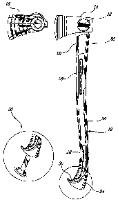
Données bibliographiques
(51) Classification internationale des brevets (CIB):
  • B25G 01/10 (2006.01)
  • B25G 03/34 (2006.01)
  • B26B 23/00 (2006.01)
(72) Inventeurs :
  • FORTIER, ANDRE (Canada)
  • JULIEN, PATRICK (Canada)
  • LAMARRE, SIMON (Canada)
  • GUAY, MARIE-CLAUDE (Canada)
(73) Titulaires :
  • GARANT GP
(71) Demandeurs :
  • GARANT GP (Canada)
(74) Agent: LAVERY, DE BILLY, LLP
(74) Co-agent:
(45) Délivré:
(22) Date de dépôt: 2007-04-20
(41) Mise à la disponibilité du public: 2007-10-21
Licence disponible: S.O.
Cédé au domaine public: S.O.
(25) Langue des documents déposés: Anglais

Traité de coopération en matière de brevets (PCT): Non

(30) Données de priorité de la demande:
Numéro de la demande Pays / territoire Date
2,544,455 (Canada) 2006-04-21

Abrégés

Abrégé anglais


A hand tool and a method of fabrication thereof, the tool comprising a head
having a neck portion provided with perforations, and a handle comprising a
core and a sleeve, the sleeve of the handle being molded over the core and the
neck, the material of the sleeve forming a bridge between the core and the
neck and filling the perforations of the neck.

Revendications

Note : Les revendications sont présentées dans la langue officielle dans laquelle elles ont été soumises.


8
CLAIMS
1. A tool, comprising:
a head, said head having a neck portion provided with
perforations; and
a handle, comprising a core and a sleeve;
wherein said sleeve of the handle is molded over said
core and said neck, a material of the sleeve forming a bridge between
the core and the neck and filling said perforations of the neck.
2. The tool of claim 1, wherein said material of the sleeve
comprises a composite material, and said head made of steel.
3. The tool of claim 1, wherein the material of the sleeve
encapsulates said neck on three sides thereof.
4. The tool of claim 1, wherein said core of the handle is a
rod encapsulated in the material of the sleeve, at a center of the
sleeve, over at least a part of a length of the sleeve from an upper end
thereof.
5. The tool of claim 1, wherein said handle further
comprises a coating, extending generally longitudinally from an upper
end of the sleeve to a free end region of the sleeve, over at least a part
of said sleeve.
6. The tool of claim 4, wherein said rod is made of one of: i)
polypropylene, ii) wood fibers, and iii) foam.

9
7. The tool of claim 5, wherein said coating is a
thermoplastic material.
8. The tool of claim 5, wherein said coating comprises
relieves.
9. The tool of claim 1, wherein said sleeve has a varying
section along a length of the handle.
10. The tool of claim 5, wherein said sleeve comprises ribbed
sections, said coating filling said ribbed sections.
11. The tool of claim 1, wherein said sleeve has a curved
shape at a free end of said handle.
12. The tool of claim 1, wherein said sleeve accommodates
at least one recess.
13. The tool of claim 1, wherein said handle further
comprises implements foldingly mounted in the sleeve thereof.
14. The tool of claim 1, further comprising a case for the
head.
15. The tool of claim 14, wherein said case comprises a
magnet element on an inner surface thereof, said magnet element
securing the case to the head.
16. The tool of claim 14, wherein said case comprises a hook
for hanging the tool, once the case is in place over the head of the tool.

17. A method for mounting a head to a handle to form a hand
tool, comprising the steps of:
providing a head having a neck with perforations;
providing a core;
positioning the core and the head in a mold for a handle,
a free end of the neck being in the continuity of an end of the core; and
injecting a material in the mold;
whereby the material bridges a separation between the
free end of the neck and the end of the core, fills the perforations of the
neck and forms a sleeve.
18. The method of claim 17, wherein said step of providing a
head comprises providing a head made of steel.
19. The method of claim 17, further comprising providing a
coating over at least parts of the sleeve.
20. The method of claim 17, wherein said step of injecting a
material in the mold for the handle comprises injecting a composite
material.
21. The method of claim 17, wherein said step of injecting a
material in the mold for the handle comprises injecting one of: i) nylon
reinforced with glass fibers and ii) charged polyethylene.
22. The method of claim 17, wherein said step of providing a
core comprises providing a rod.
23. The method of claim 17, wherein said step of providing a
core comprises providing a member in one of: i) polypropylene, ii)
wood fibers and iii) high-density foam.

11
24. The method of claim 17, wherein the mold for the handle
provides a hook shape at a free end of the sleeve.
25. The method of claim 17, wherein the mold for the handle
provides at least one recess in the sleeve.
26. The method of claim 17, wherein said step of providing a
head comprises providing a head including at least one of: i) a blade, ii)
a hammer face, iii) an impact face, iv) a nail puller and v) a claw.
27. The method of claim 17, wherein said step of providing a
head comprises providing a head including a region, on a face thereof,
for receiving a magnet element of a case.

Description

Note : Les descriptions sont présentées dans la langue officielle dans laquelle elles ont été soumises.

i i li,
CA 02585632 2007-04-20
2
TITLE OF THE INVENTION
Hand tool
FIELD OF THE INVENTION
[0001] The present invention relates to hand tools.
SUMMARY
[0002] There is provided a tool, comprising a head having a neck
portion provided with perforations; and a handle comprising a core and a
sleeve, the sleeve of the handle being molded over the core and the neck, a
material of the sleeve forming a bridge between the core and the neck and
filling the perforations of the neck.
[0003] There is further provided a method for mounting a head to a
handle to form a hand tool, comprising the steps of providing a head having a
neck with perforations; providing a core; positioning the core and the head in
a
mold for a handle, a free end of the neck being in the continuity of an end of
the
core; and injecting a material in the mold; the material bridging a separation
between the free end of the neck and the end of the core and filling the
perforations of the neck and forming a sleeve.
[0004] Other objects, advantages and features of the present
invention will become more apparent upon reading of the following non-
restrictive description of embodiments thereof, given by way of example only
with reference to the accompanying drawings.

CA 02585632 2007-04-20
3
BRIEF DESCRIPTION OF THE DRAWINGS
[0005] In the appended drawings:
[0006] Figure 1 is a side view of a tool according to a first
embodiment of the present invention;
[0007] Figure 2 is a side view of a tool according to a second
embodiment of the present invention;
[0008] Figure 3 is a side view of a tool according to a third
embodiment of the present invention;
[0009] Figure 4 is a cut off view of a section of a handle of a tool
according to an embodiment of the present invention;
[0010] Figure 5 shows mounting the head and the handle of a tool
according to an embodiment of the present invention;
[0011] Figure 6 is a side view of a tool according to a fourth
embodiment of the present invention; and
[0012] Figures 7-11 illustrate a case for a tool according to
embodiments of the present invention.
DESCRIPTION OF EMBODIMENTS OF THE INVENTION
[0013] A tool as generally illustrated in Figures 1-3 of the appended

CA 02585632 2007-04-20
4
drawings comprises a handle 12 and a head 14.
[0014] The head 14 comprises a neck 22 provided with perforations
50, as best seen in Figure 5.
[0015] The head 14 is connected to the handle 12 by overmolding
the material of the handle 12 over the neck 22, whereby the material of the
handle encapsulates the neck 22 and fills the perforations 50 of the neck 22.
[0016] The neck 22 may be encapsulated on three sides thereof,
leaving a side 28 with the material of the neck, such as steel for example,
apparent to protect the handle 12 from damages from mishaps, i.e. when
landing the handie 12 against a workpiece for example.
[0017] The handle 12 comprises a sleeve 13 and a core 42. The
core 42 is encapsulated in the sleeve 13, generally centrally relative to the
width of the sleeve 13, over a given length of the sleeve, as shown for
example
in Figures 4 and 5, from an upper end thereof.
[0018] The core 42 is encapsulated in the sleeve 13, together with
the neck 22 of the head, the core 42 and the neck 22 remaining separated by a
thickness of the material of the sleeve 13. This thickness of material is of
about
7/32 inches, to avoid deformation of the material of the sleeve 13 at this
location upon cooling, and to create a bridge between the upper end of the
core
42 and the lower end of the neck 22 for transverse resistance of the handle.
[0019] The sleeve 13 is generally made in a composite material,
such as nylon reinforced with glass fibers, or charged polyethylene (PE) for

CA 02585632 2007-04-20
example.
[0020] The core 42 may be a molded polypropylene rod, or a rod in
a lighter, less dense material such as wood fibers or high-density foam,
filling
the sleeve 13.
[0021] The handle 12 may further comprise a coating 20, in
thermoplastic rubber for example, extending generally longitudinally from the
upper end of the sleeve 13 to a bottom end region of the sleeve 13, in the
free
end region 24 of the handle 12, on parts of the sleeve 13, on each side
thereof.
Such coating allows an unimpeded up and down movement of the hand of a
user along the handle 12. The coating 20 may comprise relieves 26, for
optimizing the grip by the user. Such relieves 26 may further be used as
markers for hand positioning.
[0022] Variations of sections and of material in the handle 12 may be
contemplated to dampen vibration. As shown in a cut off view of Figure 4 for
example, the sleeve 13 may comprise ribbed sections 40, which are filled with
the material of the coating 20.
[0023] At the free end 24 of the handle, the sleeve 13 may have a
curved shape 32 for an enhanced grip and for preventing dropping the tool.
[0024] A recess 30 may be accommodated in the sleeve 13 of the
handle 12, for securing sharpening files for example, as shown in Figure 6.
[0025] As shown in the embodiment illustrated in Figure 6, additional
implements, such as a tooth 36 or a hook 38 for example, may be provided

CA 02585632 2007-04-20
6
about the handle 12, in a folding mount, folding into the sleeve of handle 12
in
an out-of-use position, and projecting out from the surface of the sleeve when
used.
[0026] The head 14 may be a blade, in the case of a multipurpose
axe (Figure 1), or of a hatchet (Figure 2), or of a splitting maul (Figure 3)
for
example. Other hand tools may be considered with different types of heads,
such as hammers or impact instruments for example.
[0027] In the present illustrations, the head is generally a blade, but
it could comprise a face and claw in the case of a hammer for example. The
head 14 may be provided with a nail puller 34 (see Figure 6).
[0028] The head 14 is generally made of steel.
[0029] The head 14 includes a region 16, on a face thereof, intended
for receiving a magnet element of a case 18, so that, when in place, the case
18 is secured to the head 14, as will be described hereinafter in relation to
Figures 7 to 11.
[0030] As illustrated in Figures 8, 9 and 11, the case 18 is provided
with a magnet element 43 on an inner face thereof, which engages the region
16 of the head 14 of the tool, so that, when in place, the case 18, further
supported by a tooth 44 for example, is secured to the head 14.
[0031] The case 18 may comprise a blade protection feature 46 in a
region covering the blade.

l I il
CA 02585632 2007-04-20
7
[0032] Moreover, the case 18 may be provided with a hook 40, as
shown in Figures 7 to 10, allowing hanging the tool on a wall for storage
purposes for example, and/or a clip 45, as shown in Figure 11, for fixing to a
belt worn by the user for example, for transportation.
[0033] A method according to an embodiment of another aspect of
the present invention generally comprises positioning a core and a head in an
injection mold and injecting a sleeve around the rod and the neck of the head.
The core fills the sleeve of the handle, the material of the sleeve joining
the
neck and the core by forming a bridge between the neck and the core, and
penetrating perforations of the neck for stronger junction.
[0034] Although the present invention has been described
hereinabove by way of embodiments thereof, it may be modified, without
departing from the nature and teachings of the subject invention as defined in
the appended claims.

Dessin représentatif
Une figure unique qui représente un dessin illustrant l'invention.
États administratifs

2024-08-01 : Dans le cadre de la transition vers les Brevets de nouvelle génération (BNG), la base de données sur les brevets canadiens (BDBC) contient désormais un Historique d'événement plus détaillé, qui reproduit le Journal des événements de notre nouvelle solution interne.

Veuillez noter que les événements débutant par « Inactive : » se réfèrent à des événements qui ne sont plus utilisés dans notre nouvelle solution interne.

Pour une meilleure compréhension de l'état de la demande ou brevet qui figure sur cette page, la rubrique Mise en garde , et les descriptions de Brevet , Historique d'événement , Taxes périodiques et Historique des paiements devraient être consultées.

Historique d'événement

Description Date
Le délai pour l'annulation est expiré 2013-04-22
Demande non rétablie avant l'échéance 2013-04-22
Inactive : Abandon.-RE+surtaxe impayées-Corr envoyée 2012-04-20
Réputée abandonnée - omission de répondre à un avis sur les taxes pour le maintien en état 2012-04-20
Lettre envoyée 2009-03-18
Demande de correction du demandeur reçue 2008-09-16
Inactive : Transfert individuel 2008-09-16
Demande publiée (accessible au public) 2007-10-21
Inactive : Page couverture publiée 2007-10-21
Inactive : CIB en 1re position 2007-10-16
Inactive : CIB attribuée 2007-10-16
Lettre envoyée 2007-08-30
Inactive : Transfert individuel 2007-06-07
Inactive : Lettre de courtoisie - Preuve 2007-05-22
Demande reçue - nationale ordinaire 2007-05-17
Inactive : Certificat de dépôt - Sans RE (Anglais) 2007-05-17

Historique d'abandonnement

Date d'abandonnement Raison Date de rétablissement
2012-04-20

Taxes périodiques

Le dernier paiement a été reçu le 2011-04-13

Avis : Si le paiement en totalité n'a pas été reçu au plus tard à la date indiquée, une taxe supplémentaire peut être imposée, soit une des taxes suivantes :

  • taxe de rétablissement ;
  • taxe pour paiement en souffrance ; ou
  • taxe additionnelle pour le renversement d'une péremption réputée.

Les taxes sur les brevets sont ajustées au 1er janvier de chaque année. Les montants ci-dessus sont les montants actuels s'ils sont reçus au plus tard le 31 décembre de l'année en cours.
Veuillez vous référer à la page web des taxes sur les brevets de l'OPIC pour voir tous les montants actuels des taxes.

Historique des taxes

Type de taxes Anniversaire Échéance Date payée
Taxe pour le dépôt - générale 2007-04-20
Enregistrement d'un document 2007-06-07
Enregistrement d'un document 2008-09-16
TM (demande, 2e anniv.) - générale 02 2009-04-20 2009-04-06
TM (demande, 3e anniv.) - générale 03 2010-04-20 2010-03-26
TM (demande, 4e anniv.) - générale 04 2011-04-20 2011-04-13
Titulaires au dossier

Les titulaires actuels et antérieures au dossier sont affichés en ordre alphabétique.

Titulaires actuels au dossier
GARANT GP
Titulaires antérieures au dossier
ANDRE FORTIER
MARIE-CLAUDE GUAY
PATRICK JULIEN
SIMON LAMARRE
Les propriétaires antérieurs qui ne figurent pas dans la liste des « Propriétaires au dossier » apparaîtront dans d'autres documents au dossier.
Documents

Pour visionner les fichiers sélectionnés, entrer le code reCAPTCHA :


Pour visualiser une image, cliquer sur un lien dans la colonne description du document (Temporairement non-disponible). Pour télécharger l'image (les images), cliquer l'une ou plusieurs cases à cocher dans la première colonne et ensuite cliquer sur le bouton "Télécharger sélection en format PDF (archive Zip)" ou le bouton "Télécharger sélection (en un fichier PDF fusionné)".

Liste des documents de brevet publiés et non publiés sur la BDBC .

Si vous avez des difficultés à accéder au contenu, veuillez communiquer avec le Centre de services à la clientèle au 1-866-997-1936, ou envoyer un courriel au Centre de service à la clientèle de l'OPIC.

({010=Tous les documents, 020=Au moment du dépôt, 030=Au moment de la mise à la disponibilité du public, 040=À la délivrance, 050=Examen, 060=Correspondance reçue, 070=Divers, 080=Correspondance envoyée, 090=Paiement})


Description du
Document 
Date
(aaaa-mm-jj) 
Nombre de pages   Taille de l'image (Ko) 
Description 2007-04-19 6 175
Revendications 2007-04-19 4 93
Abrégé 2007-04-19 1 9
Dessins 2007-04-19 11 231
Dessin représentatif 2007-09-27 1 9
Certificat de dépôt (anglais) 2007-05-16 1 159
Courtoisie - Certificat d'enregistrement (document(s) connexe(s)) 2007-08-29 1 104
Rappel de taxe de maintien due 2008-12-22 1 113
Courtoisie - Certificat d'enregistrement (document(s) connexe(s)) 2009-03-17 1 102
Rappel - requête d'examen 2011-12-20 1 118
Courtoisie - Lettre d'abandon (taxe de maintien en état) 2012-06-14 1 173
Courtoisie - Lettre d'abandon (requête d'examen) 2012-07-29 1 164
Correspondance 2007-05-16 1 25
Correspondance 2008-09-15 3 70
Taxes 2009-04-05 1 50