Note: Descriptions are shown in the official language in which they were submitted.
CA 02585807 2007-04-25
WO 2006/050090 PCT/US2005/038923
TOILET SEAT L]FTING AND LOWERING DEVICE
The present invention relates to toilets, and in particular, to toilet seat
lifting and
lowering devices.
BACKGROUND OF THE INVENTION
FIG. 14 shows prior art toilet 200. Toilet seat 202 is pivotally connected to
toilet 200.
To use a toilet a female will usually sit on seat 202 to urinate and/or
defecate. In
contrast, a male will usually lift seat 202 before urinating and sit on it
only to
defecate. Then, if the seat is raised, a female will need to lower it to
either urinate or
defecate and a male will need to lower it to defecate.
Because of its proximity to human waste, the act of lifting the toilet seat
can be
potentially harmful. Bacteria and waste on and underneath the seat can get
onto the
hands of the individual using the toilet. To remedy this problem, there are
some
devices in the prior art designed to enable a user to lift the toilet seat
without using his
hands. However, these devices are complicated to make and expensive to produce
and purchase. Also, they are not commercially viable due to their poor design,
impracticality and lack of adhesion to plumbing codes.
What is needed is a better toilet seat lifting and lowering device.
SUMMARY OF THE INVENTION
The present invention provides a toilet seat lifting and lowering device for
pivoting
the seat to its raised position and for pivoting it back to its horizontal
position without
having to touch the seat. A first lever arm is rigidly attached at one end to
a first part
of a torque transfer mechanism and at its other end to a foot pedal and a
second lever
arm is rigidly attached at one end to a second part of the torque transfer
mechanism
and at its other end to the toilet seat. With the toilet seat in its
horizontal position, a
downward force on the pedal produces a rotation of the first part of the
torque transfer
mechanism which produces an opposite rotation of the second part of the torque
transfer mechanism causing the toilet seat to pivot to its raised position.
Lifting the
pedal, preferably by providing an upward force under the pedal, lowers the
seat to the
horizontal position. In a preferred embodiment, a counterweight positionable
on the
first lever arm is provided to provide a constant torque to partially oppose
the torque
CA 02585807 2007-04-25
WO 2006/050090 PCT/US2005/038923
produced by the weight of the toilet seat about its pivot axis. In a preferred
embodiment, the first and second parts of the torque transfer mechanism are
both
cams.
BRIEF DESCRIPTION OF THE DRAWINGS
FIGS. 1 - 4 show a first preferred embodiment of the prior art.
FIG. 5 shows a preferred pedal.
FIGS. 6 - 9 show a second preferred embodiment of the prior art.
FIG. 10 shows another preferred pedal.
FIGS. 11 - 13 show a preferred gear and a gear follower.
FIGS. 14 - 15B show a prior art toilet.
FIGS. 16A - 16B show a preferred method for installing the first preferred
embodiment.
FIGS. 17 - 19 show a third preferred embodiment.
FIGS. 20 - 22 show a another preferred pedal.
DETAILED DESCRIPTION OF THE PREFERRED EMBODIMENTS
First Preferred Embodiment
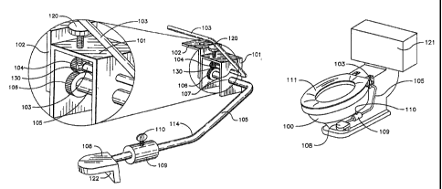
A first preferred embodiment of the present invention is shown in FIG. 1. The
first
preferred embodiment includes housing 101, adapter bracket 102, second lever
arm
103 connected to a small gear 104 at a first end. Second lever arm 103 is
slidingly
attached at its second end to seat 111 within attachment clip 112. Also the
first
preferred embodiment includes first lever arm 105 connected at one end to
pedal 108
and at the other end to large gear 106. Gears 104 and 106 form a torque
transfer
mechanism whereby torque applied at foot pedal 108 is transferred to toilet
seat 111
through second lever arm 103 extending into housing 101 through lever entry
holes
107.
First lever arm 105 extends away from housing 101 alongside toilet 100 towards
the
floor, as in FIG. 2 and FIG. 3. First lever arm 105 preferably includes pedal
108 and
adjustable counterweight 109 with screw 110. As seen in FIG. 3, second lever
arm
slides within attachment clip 112 attached to the underside of the toilet seat
111.
2
CA 02585807 2007-04-25
WO 2006/050090 PCT/US2005/038923
As seen in FIG. 4, seat 111 is raised by a user pressing his foot on pedal 108
and
lowered by placing his foot under pedal 108 and lifting pedal 108 upwards.
When a
user presses down pedal 108 with his foot, first lever arm 105 rotates
downward
(counterclockwise as viewed in FIG. 4) causing large gear 106 to rotate
counterclockwise which in turn causes small gear 104 and second lever arm 103
to
rotate clockwise. The clockwise rotation of second lever arm 103 produces a
clockwise rotation of seat 111. The upward force causes seat 111 to lift.
Conversely,
toilet seat 111 is lowered by the user placing his foot under pedal 108 and
lifting
upward on peda1108.
When seat 111 is raised, second lever arm 103 slides from one end of
attachment clip
112 to the other. As shown in FIG. 4, seat 111 is lifted with only a small
angular
rotation of second lever arm 103.
As shown in FIG. 1, the first preferred embodiment includes thumb screw 120.
Thumb screw 120 passes from the outside into the interior of housing 101. As
the user
steps on pedal 108, gear 106 rotates counterclockwise and gear 104 rotates
clockwise
(see also FIG. 4). As gear 104 rotates clockwise stub 130 contacts screw 120.
This
causes the rotation of second lever arm 103 to stop and prevents seat 111 from
hitting
toilet tank 121 (FIGS. 2 and 3).
Counterweight
Counterweight 109 is preferably movable up and down the length of the first
lever
arm 105 between pedal 108 and the first lever arm angle 114. Once
counterweight
109 has been appropriately positioned, its position is secured by tightening
screw 110.
A function of couuterweight 109 is to provide a torque countering the torque
provided
by the weight of the toilet seat about the pivot position of the toilet seat.
For example,
as counterweight 109 is moved closer to pedal 108, second lever arm 103 exerts
greater angular force on the underside of toilet seat 111. A preferred
position of
counterweight 109 is the one at which the torque produced by counterweight 109
and
large lever arm 105 almost (but not quite) balances the torque produced by the
weight
of toilet seat 111 so that in the seat's lowered position only a small
downward force
on pedal 108 is required to raise the seat to its full upward position.
Therefore, as
toilet seat 111 is lowered the force exerted by second lever arm 103 and the
extra
3
CA 02585807 2007-04-25
WO 2006/050090 PCT/US2005/038923
weight provided by counterweight 109 help slow the descent of seat 111 and
therefore
helps prevent toilet seat 111 from being slammed onto the rim of the toilet.
Pedal
Pedal 108 is shaped to permit space 122 under the upper surface of the pedal
to
position the foot for lifting the pedal 108. The pedal preferably possesses a
multiplicity of holes 123 (FIG. 5) that permit the insertion of first lever
ann 105. A
user can choose which of the holes to insert first lever arm 105. The distance
above
the floor pedal 108 rests when toilet seat 111 is raised is thereby adjusted.
Preferred Method for Installing First Preferred Embodiment
FIGS. 14, 15A and 15B show prior art toilet 200. Prior art toilet 200 includes
lip 201,
bolts 203, hinges 207 and seat 202.
The method for installing the first preferred embodiment is extremely simple
and can
be accoinplished very quickly and used on a variety of toilet types, shapes
and sizes.
For example, FIGS. 16A - 16B illustrate a preferred method for installing the
first
preferred embodiment.
Preferably, attachment clip 112 is first screwed into seat 202. Then, second
lever arm
103 is positioned between attachment clip 112 and seat 202. Then, pre-existing
bolt
203 is used to bolt adapter bracket 102 underneath lip 201.
The first preferred embodiment is now ready for in accordance with procedures
similar to that explained above.
Second Preferred Embodiment
The second preferred embodiment includes housing 301 (FIG. 6) and cams 304 and
306. It should be noted that cams 304 and 306 have been modified from gears
104
and 106 shown in the first preferred embodiment. (The reader should note that
cams
304 and 306 may also correctly be referred to as single-toothed gears or cam
gears.
Although cams 304 and 306 are shaped differently than gears 104 and 106, cams
304
and 306 are similar to gears 104 and 106 in that they both have the similar
function of
transferring rotational motion from first lever arm 105 to second lever arm
103.)
4
CA 02585807 2007-04-25
WO 2006/050090 PCT/US2005/038923
Housing
In addition to housing cams 304 and 306, housing 301 also is utilized to
connect seat
111 to toilet 100 (FIG. 7). Therefore, by utilization of housing 301, it is
not necessary
to include a separate adapter bracket such as adapter bracket 102 shown in the
first
preferred embodiment. Preferably, rubber gasket 279 is placed between housing
301
and toilet 100 (FIG. 8).
Cams
The second preferred embodiment includes second lever arm 103 pin connected to
upper cam 304 and first lever arm 105 pin connected to lower cam 306. As shown
in
FIGS. 6, 9 and 11 - 13, cam 304 is preferably in the general shape of a single-
toothed
gear having single tooth 304a and cam 306 has a single groove 306a to receive
single
tooth 304a. The cams of the second preferred embodiinent replace gears 104 and
106
of the first preferred embodiment. Like gears 104 and 106, cams 304 and 306
mesh
with each other and enable first lever arm 105 to transfer rotational motion
to second
lever arm 103. In contrast to gears 104 and 106, cam 304 has one large single
tooth
and cam 306 has one large single groove. Hence, cams 304 and 306 are less
likely to
break or wear down after extended usage. They are also less expensive to
manufacture than gears. For example, it is estimated that from a
manufacture/supplier
cams 304 and 306 cost approximately $0.15 each. In comparison, gears 104 and
106
cost approximately $4.00 each.
In the second preferred embodiment, first lever arm 105 extends away from
housing
301 alongside toilet 100 towards the floor, as shown in FIGS. 7 and S. Pedal
126 with
clutch/crane receptor 208 is attached to the end of first lever arm 105.
Second lever
arm 103 is inserted into the side of toilet seat 111 by means of attachment
slot 312.
Attachment slot 312 replaces attachment clip 112 of the first preferred
embodiment.
As shown in FIG. 9, seat 111 is raised by pressing pedal 126 with the foot.
When a
user presses pedal 126 with his foot, first lever arm 105 rotates
counterclockwise
causing second lever arm 103 to rotate clockwise. The clockwise rotation of
second
lever arm 103 causes second lever arm 103 to exert an upward force onto seat
111.
CA 02585807 2007-04-25
WO 2006/050090 PCT/US2005/038923
The upward force causes seat 111 to lift. Conversely, toilet seat 111 is
lowered by the
user placing his foot in pedal recess 122 (FIG. 10) and lifting upward on
pedal 126.
When seat 111 is lifted, second lever arm 103 slides from one end of
attachment slot
312 to the other allowing seat 111 to be lifted through angle (3 with only a
small
angular rotation a of first lever arm 105. This angular rotation is shown in
FIGS. 11 -
13.
As shown in FIGS. 9, and 11 - 13, thumb screw 125 passes from the outside into
the
interior of housing 101. Thumb screw 125 is used to control the stopping
position of
second lever arm 103 as seat 111 is raised. By controlling the stopping
position, seat
111 is prevented from hitting toilet tank 121. Locking nut 125b is utilized to
help
ensure that the position of thumb screw 125 does not accidentally shift during
usage.
Pedal
Pedal 126 preferably weights approximately 1.5 pounds. In addition to
functioning as
a place for the user to put his foot, the extra weight of pedal 126 also
allows the pedal
to function as a counterweight. As with counterweight 109 discussed in the
first
preferred embodiment, counterweighted pedal 126 helps slow the descent of seat
111
and therefore helps prevent toilet seat 111 from being slammed onto the rim of
the
toilet.
As shown in FIGS. 9 and 10, pedal 126 is shaped to include space 122 to
position the
foot for lifting the pedal. As with the first preferred einbodiment, peda1126
possesses
a multiplicity of holes 123 that permit the insertion offirst lever arm 105.
The top of
pedal 126 includes a crutch/cane receptacle 208 that will accommodate the tip
of a
crutch or cane, making it easier to depress the pedal for handicapped
individuals.
Third Preferred Embodiment
A third preferred embodiment is shown in FIGS. 17 - 19. As in the first
preferred
embodiment, seat 202 is connected to toilet 210 via hinges 207 and adapter
bracket
102 is bolted to lip 201. However, in the third preferred embodiment, it is
not
necessary to utilize an attachment clip or an attachment slot.
6
CA 02585807 2007-04-25
WO 2006/050090 PCT/US2005/038923
In FIG. 19, the user has stepped on pedal 108 and second lever arm 103 has
exerted
an upward force on seat 202 in a fashion similar to that described above in
reference
to the earlier embodiments. Hinge 207 allows seat 202 to easily pivot about
the hinge
between the position shown in FIG. 18 and the position shown in FIG. 19. It
should
be noted that in FIG. 19 seat 202 is not completely vertical, but rather is
leaning
slightly to the left.
To lower seat 202, the user places his foot under pedal 108 and lifts upward
in a
fashion similar to that described above in reference to the earlier
embodiments. The
force of gravity acting on seat 202 causes the seat to lower as second lever
arm 103
goes to the position shown in FIG. 18. Also, it should be noted that the third
preferred
embodiment also preferably includes a locknut similar to locknut 125b (shown
in
FIGS. 11 - 13) and also preferably includes a gasket similar to gasket 279
(shown in
FIG. 8).
Preferred Pedal
FIGS. 20 - 22 show preferred peda1261. Preferred peda1261 includes interior
weight
262. In one preferred embodiment weight 262 weights approximately 2 pounds.
Pedal 261 can be connected to first lever ann 105 via upper hole 263 or via
lower hole
264. It is preferable to connect pedal 261 to first lever arm 105 via upper
hole 263
(FIG. 21) for a taller toilet (i.e., a 17-inch toilet) and it is preferable to
connect pedal
261 to first lever arm 105 via lower hole 264 (FIG. 22) for a shorter toilet
(i.e., a 14-
inch toilet). Pedal 261 also includes an extended vertical section 267 under
horizontal
portion 268. Vertical section 267 allows the user additional room to place his
foot
when lifting up on pedal 261 to lower the toilet seat.
-----------------------------
Although the above-preferred embodiments have been described with specificity,
persons skilled in this art will recognize that many changes to the specific
embodiments disclosed above could be made without departing from the spirit of
the
invention. Therefore, the attached claims and their legal equivalents should
determine
the scope of the invention.
7