Note: Descriptions are shown in the official language in which they were submitted.
CA 02585899 2007-04-23
APPARATUS, AND ASSOCIATED METHOD, FOR GENERATING AN
ALERT TO NOTIFY EMERGENCY PERSONNEL OF A VEHICULAR
EMERGENCY
The present invention relates generally to a manner by which automatically to
alert
a public safety access point (PSAP), or other emergency personnel dispatch
station, of the
occurrence of a vehicular emergency. More particularly, the present invention
relates to
apparatus, and an associated method, that notifies the PSAP, or other station,
of the
occurrence with identification of the vehicle and additional information about
the
vehicular emergency.
A BluetoothTM or other local area transceiver is mounted at the vehicle. When
the
vehicular emergency occurs, the local area transceiver communicates with a
cellular
mobile station, or other wide area transceiver, that also has local area
communication
capabilities. And, the cellular mobile station, or other wide area
transceiver,
communicates with the PSAP. Communications between the wide area transceiver
and
the PSAP are carried out using TTY (text telephony) devices located at the
wide area
transceiver and at the PSAP, thereby to alert the PSAP of the vehicular
emergency.
Background of the Invention
Advancements in communication technologies have permitted the development
and deployment of many new types of communication devices and the introduction
of
many new types of communication services. For instance, the networks of
cellular
communication systems have been deployed over significant portions of the
populated
areas of the world. A subscriber to a cellular communication system
communicates with
the network part of the system through use of a cellular mobile station
positioned within a
coverage area defined by the network. A radio air interface is defined between
the mobile
station and the network and radio signals are communicated therebetween by way
of the
radio air interface.
The network of the cellular communication system is connected to other
communication networks, such as a packet data network and a conventional,
telephonic
network. Communications are thereby effectuable between the mobile station and
an
endpoint of the data network or telephonic network. Because the mobile station
communicates by way of radio signals communicated on the radio air interface,
the mobile
1
CA 02585899 2007-04-23
station need not be positioned at a location at which wireline connections are
available to
interconnect the mobile station with a communication network. Communication
mobility
is also permitted of the mobile station as the mobile station is operable free
of any fixed
connection to a communication network.
Many millions of subscribers make use of cellular communication systems
through
which to communicate telephonically and to communicate data. Many cellular
mobile
stations also provide for communications by hearing-impaired users. Such
mobile stations
include TTY (Text Telephony) elements, typically including TTY modems, that
provide
for textual entry of data by a user at the mobile station as well as reception
of TTY data
displayable in visual form for the user of the mobile station.
Use of a cellular communication system through which to communicate provides
many conveniences, e.g., permitting subscribers to communicate even when
positioned at
locations at which wireline connections are unavailable. A subscriber is able
to
communicate, for instance, when traveling in a motor vehicle. Moreover,
cellular
communication systems not only provide for convenience, but also are
advantageously
utilized for purposes of personal and public safety. A subscriber is able to
communicate,
using a cellular communication system, with emergency personnel, such as those
of an
emergency dispatch center to request emergency assistance and to report
emergency
conditions. Emergency dispatch centers, herein referred to, at times, as
public safety
access points (PSAPs), have equipment and personnel for communicating with
those
requesting assistance. Such PSAPs also typically include TTY devices to
communicate
with requesters that utilize TTY devices.
Recent attention has been directed towards manners by which automatically to
report vehicular emergencies, e.g., accidents in which airbags are deployed or
in which a
vehicle is overturned. Automatic reporting ensures that emergency personnel
shall be
informed of the vehicular emergency, thereby to be able to respond to the
emergency.
Various problems have heretofore limited the deployment of automated
mechanisms in
vehicles for the reporting of the vehicular emergencies. While every vehicle
can be
outfitted with a cellular mobile station that permanently forms part of the
vehicle, mobile
stations require SIM cards that uniquely identify each mobile station.
Outfitting each
vehicle with a separate SIM card is impractical due to reasons of cost, lack
of availability
2
CA 02585899 2007-04-23
of IMSI values, and issues regarding recovery of SIM cards when the vehicle is
no longer
operated.
A need remains, therefore, to provide a manner by which automatically to
report a
vehicular emergency.
It is in light of this background information related to emergency reporting
of
vehicular emergencies making use of a radio communication system that the
significant
improvements of the present invention have evolved.
Brief Description of the Drawings
Figure 1 illustrates a functional block diagram of a communication system in
which an embodiment of the present invention is operable.
Figure 2 illustrates a functional block diagram illustrating portions of the
communication system shown in Figure 1.
Figure 3 illustrates a process diagram representative of operation of an
embodiment of the present invention.
Figure 4 illustrates a method flow diagram listing the method of operation of
an
embodiment of the present invention.
Detailed Description
The present invention, accordingly, advantageously provides apparatus, and an
associated method, by which automatically to alert a PSAP (Public Safety
Access Point),
or other emergency personnel dispatch station, of the occurrence of a
vehicular
emergency.
Through operation of an embodiment of the present invention, a manner is
provided to notify the PSAP, or other station, of the occurrence with
identification of the
vehicle and additional information about the vehicular emergency.
In one aspect of the present invention, a BluetoothTM, or other, local area
transceiver is mounted at the vehicle. When the vehicular emergency occurs,
the local
area transceiver communicates with a cellular mobile station or other wide
area transceiver
that also has local area communication capabilities. And, the cellular mobile
station
communicates with the PSAP. Communications between the cellular mobile station
and
3
CA 02585899 2007-04-23
the PSAP are carried out using TTY devices located at the cellular mobile
station and at
the PSAP to alert the emergency personnel of the occurrence of the emergency.
In another aspect of the present invention, the local area transceiver,
mounted at
the vehicle, searches for the presence of the cellular, or other wide area,
transceiver.
When such a wide area transceiver having local area communication capabilities
is within
proximity to the local area transceiver, the local area transceiver obtains an
indication of
the identity of the local area transceiver. The identity comprises, for
instance, an IP
(Internet Protocol) address of the local area transceiver positioned together
with the
cellular mobile station. That is to say, the local area transceiver mounted at
the vehicle
searches for a paired transceiver, i.e., a transceiver operable to communicate
with the
vehicular-mounted local area transceiver.
In another aspect of the present invention, the local area transceiver is
caused to
search for the presence of the cellular mobile station having the local area
transceiver
capability responsive to a vehicular trip start event. The vehicular trip
start event
comprises, for instance, the turning of an ignition switch at the vehicle at
which the
vehicular-positioned local area transceiver is mounted. Or, the vehicular trip
start event
comprises, e.g., operator actuation of an actuation switch. For instance, a
switch
positioned at the passenger compartment of the vehicle, available for
actuation by a driver
of the vehicle is actuated when the driver elects to commence the search
operation for the
presence of a cellular mobile station having a local area transceiver forming
a portion
thereof.
In another aspect of the present invention, a storage element, such as an
accessible
memory location, is used to store the identity of the transceiver identified
by the vehicular-
positioned local area transceiver. The memory location is later accessed in
the event that a
report of a vehicular emergency is required. The identity is used to address a
message that
is sent by the vehicular-mounted local area transceiver to the transceiver
identified by the
identifier stored at the memory location.
In another aspect of the present invention, the message, once provided to the
transceiver identified to be in proximity to the vehicular-mounted
transceiver, is
communicated to the PSAP using the radio air interface of the cellular
communication
system and the network parts extending to the PSAP.
4
CA 02585899 2007-04-23
In another aspect of the present invention, the indicia are obtained of the
identity of
the vehicle, such as its VIN (Vehicular Identification Number) and the type of
vehicular
emergency. The type of vehicular emergency is identified by, e.g., detecting
deployment
of airbags, detecting overturning of the vehicle, or detection of some other
anomaly
condition.
In another aspect of the present invention, the cellular mobile station
includes a
TTY element, such as a TTY modem, capable of communicating TTY-formatted data
with
the PSAP. The PSAP also includes TTY functionality; viz., the PSAP also
includes a TTY
modem, capable of exchanging TTY-formatted data with the cellular mobile
station.
Information contained in the message sent by the cellular mobile station to
report on the
occurrence of the vehicular emergency is displayable upon a monitor connected
to the
TTY modem of the PSAP. Appropriate dispatch of personnel is made in response
to the
vehicular emergency report.
Advantage is taken of the common usage of cellular mobile stations. Passengers
in
a vehicle carry cellular mobile stations that also have BluetoothTM, or other
local area
transceiver, capabilities. The vehicular-mounted local area transceiver
searches for the
presence of a cellular mobile station within proximity thereto. And, when a
cellular
mobile station having the local area transceiver capabilities is detected, its
identity is
stored and used to route a message in the event of the occurrence of a
vehicular
emergency. The message includes the identification of the vehicle, its
location, such as
provided by a GPS receiver, an indication of the type of emergency, and any
other
appropriate information. The cellular mobile station, in turn, alerts the PSAP
of the
vehicular emergency through operation of the TTY modem. The appropriate
dispatch of
emergency personnel to respond best to the vehicular emergency is carried out,
all in
response to an automatic generation and transmission of the vehicular
emergency report.
In these and other aspects, therefore, apparatus, and an associated
methodology, is
provided for initiating communication of emergency data pursuant to a
vehicular
emergency. A paired transceiver detection initiation detector is adapted to
detect
occurrence of a vehicular trip start event. The paired transceiver detection
initiation
detector is configured to generate a paired transceiver search command
responsive to the
occurrence of the vehicular trip start event. A local transceiver is adapted
to receive the
paired transceiver search command generated by the paired transceiver
detection initiation
CA 02585899 2007-04-23
detector. The local transceiver is also adapted to receive indicia associated
with the
vehicle at which the local transceiver is positioned and to receive indication
of occurrence
of the vehicular emergency. The local transceiver is configured to perform a
paired
transceiver search responsive to the paired transceiver search command and to
generate a
vehicular emergency report responsive to the indication of the occurrence of
the vehicular
emergency.
Referring first, therefore, to Figure 1, an exemplary communication system,
shown
generally at 10, provides for communications between communication endpoints,
including mobile stations of which the mobile station 12 is representative.
The mobile
station 12 communicates by way of communication channels, here designated by
the
arrow 14, defined upon a radio air interface with a communication network,
here formed
of a radio access network 16 and a PSTN (Public Switched Telephonic Network)
18. The
networks 16 and 18 are interconnected, in conventional manner, here by way of
a gateway
22.
The radio access network is here shown to include a base transceiver station
(BTS)
24 that includes transceiver elements that transceive communication signals
with
corresponding circuitry of the mobile station 12. In conventional manner, a
typical radio
access network includes a plurality of spaced-apart base transceiver stations
that together
encompass a geographical area over which communications by, and with, mobile
stations
are permitted. Any of various communication endpoints are connectable to the
networks
16 and 18. Here, a PSAP (Public Safety Access Point) 28 is connected to the
networks 16
and 18. The PSAP is defined at an emergency dispatch center that receives
requests for
emergency assistance, and, responsive to such requests, instructs emergency
personnel to
respond to such requests. The PSAP is, e.g., in the United States, a 911-
center to which
911 emergency calls are routed. A call originated at a mobile station, such as
the mobile
station 12, is routable to the PSAP 28.
The mobile station 12 is representative of a mobile station carried by an
occupant
of a vehicle 32. That is to say, the mobile station 12 is carried by a user,
and, when the
user is positioned at the vehicle 32, the mobile station, carried by the user,
is also
positioned at the vehicle. When the user leaves the vehicle, the mobile
station, if carried
by the user, is also carried away from the vehicle. The mobile station 12 is
not fixedly
6
CA 02585899 2007-04-23
positioned at the vehicle but, rather, is likely to be positioned at the
vehicle only
temporarily.
The mobile station 12 includes a set of transceivers, a wide area network
(WAN)
transceiver 34, and a local area (LA) transceiver 36. The transceiver elements
34 and 36
are connected together in conventional manner. In the exemplary
implementation, the
wide area network transceiver forms a cellular transceiver capable of
transceiving the
communication signals that are received from, and transmitted to, the radio
access network
16. And, the local area transceiver forms a BluetoothTM transceiver capable of
sending
and receiving signals over short ranges, e.g., on the order of thirty meters
or less. The
capacity of a mobile station, such as the mobile station 12, to communicate
over a wide
area using the transceiver element 34 and to communicate over a local area
using the
transceiver element 36 is used to advantage pursuant to an embodiment of the
present
invention.
Pursuant to an embodiment of the present invention, the vehicle 32 includes
apparatus 38 of an embodiment of the present invention. The apparatus includes
a local
area transceiver 42, here also a BluetoothTM transceiver. The transceiver,
herein referred
to as a vehicular-positioned transceiver for the reason that, in the exemplary
implementation, the transceiver 42 is permanently maintained at the vehicle
32, is capable
of communicating with the transceiver 36, or corresponding transceiver of
another mobile
station when positioned in the passenger compartment of the vehicle or is
otherwise in
proximity to the transceiver 42.
The apparatus 38 further includes an initiation detector and controller 44.
The
detector and controller comprises, for instance, an application executable by
processing
circuitry. The detector and controller is positioned in communication
connectivity with
the local area transceiver and, in the exemplary implementation, both exert
control over its
operation and provides indicia to the transceiver that is communicated during
operation of
the transceiver pursuant to an embodiment of the present invention. The
detector and
controller is provided input indicia, here represented by way of the lines 48,
50 and 52.
The line 48 represents a line upon which a trip-start event indicia is
provided to the
detector and controller. The trip-start event indicia forms, for instance, an
indication of an
operator of the vehicle 32 turning an ignition switch to commence operation of
the vehicle.
And, here, the line 48 extends to the ignition switch 54, or electrical
contacts thereof.
7
CA 02585899 2007-04-23
When the operator of the vehicle turns a key in the ignition switch 54, an
indication of the
start of the vehicular engine is provided by way of the line 48 to the
detector and controller
44.
The line 50 is representative of vehicular emergency indicia that is generated
upon
the occurrence of a vehicular emergency. The indicia is generated, for
instance, upon
deployment of safety airbags, upon detection of level sensors of upending of
the vehicle,
or other type of collision sensor indications that indicate collision of the
vehicle.
And, the line 52 is representative of a line upon which vehicular identity
information, such as a vehicle identification number (VIN) is provided to the
detector and
controller. The identifier identifies the vehicle, and when the identifier
forms the VIN, the
vehicle is uniquely identified.
In operation, upon detection of the trip start event, the detector and
controller
causes the local area transceiver 42 to commence searching operations to
detect presence
of one to many paired transceivers in proximity to the transceiver 42. The
paired
transceiver is a transceiver capable of communicating with the transceiver 42
and, here,
the transceiver 36 forming a portion of the mobile station 12 defines a paired
transceiver
when the mobile station 12 is positioned in the passenger compartment of the
vehicle or
otherwise is positioned in proximity to the transceiver 42 of the apparatus
38.
In the exemplary implementation in which the transceivers 36 and 42 form
BluetoothTM-compatible transceivers, interrogation and reply messages are
generated, in
conventional manner, in conformity with standard BluetoothTM protocols. The
transceiver
36 is identified, e.g., by an IP (Internet Protocol) address. Responsive to
the search or
inquiry by the transceiver 42, a reply message, containing the IP address of
the transceiver
36 is returned to the transceiver 42. A memory element 62, connected to, or
forming part
of, the transceiver 42 is used to store the IP address, or other identifier,
that identifies the
transceiver 36. When a plurality of mobile stations 12 are positioned at the
vehicle 32 or
otherwise positioned in proximity to the transceiver 42, the identities of the
plurality of
mobile stations and indications thereof are stored at the memory element 62.
The
identities are ordered in an ordered list, according to any desired selection
criteria, and the
identities are accessed in the listed order.
In one implementation, subsequent to the initial search made by the
transceiver 42,
subsequent searches are made at periodic, or other, intervals so that the
information stored
8
CA 02585899 2007-04-23
at the memory element is timely. And, in the event that, responsive to a
search, no mobile
stations are determined to be at the vehicle 32 or otherwise in proximity
thereto,
subsequent searches are made at selected intervals to detect the presence of
mobile stations
subsequently in position in proximity to the transceiver 42.
In the absence of occurrence of a vehicular emergency, the detection of the
trip
start event and subsequent searching for transceivers in proximity to the
vehicular-
positioned transceiver 42 is repeated each time that a trip start event is
detected. Upon the
occurrence of a vehicular emergency, indication of its occurrence is provided
to the
detector and controller 44 by way of the line 52. And, the detector and
controller alerts the
vehicular-positioned transceiver 42 of the occurrence. In response, the
transceiver 42 is
caused to generate a message that is communicated to the transceiver 36 whose
identity is
stored at the memory element 62. That is to say, the contents of the memory
element are
retrieved in order to identity to where to route a message that is generated
by the
vehicular-positioned transceiver.
Once ascertained, the memory contents are used to address the message and the
message is populated with indications of the vehicular emergency together with
the
identity of the vehicle. The message is sent and delivered to the identified
transceiver,
here the transceiver 36. Information contained in the message is utilized
pursuant to a
request made by the wide area network transceiver 34 to the PSAP 28.
In the exemplary implementation, the transceiver 34 includes a TTY modem 66
capable of transmitting TTY-formatted data. The PSAP 28 also includes a TTY
modem,
designated at 68, also capable of communicating TTY-formatted data. Subsequent
to
conventional call set-up with the PSAP, in the exemplary implementation, the
information
associated with the vehicular emergency is communicated by way of the TTY
modems.
The call is placed automatically, and the information is communicated
automatically,
without need for user interaction. In the event that the occupants of the
vehicle are unable
to place a call for emergency assistance or provide other information, the
information
needed to alert the PSAP and the personnel thereat of the occurrence of the
vehicular
emergency is automatically provided.
In a further implementation, indicia provided to the detector and controller
also
includes GPS (Global Positioning System) positioning information, and such
positioning
information is included in the message generated by the local area transceiver
42 and is
9
CA 02585899 2007-04-23
communicated to the PSAP. Personnel at the emergency dispatch center at which
the
PSAP is positioned are able to respond to the exact location at which the
vehicular
emergency has occurred.
Figure 2 illustrates a representation of various of the elements shown in the
communication system of Figure 1. Again, the vehicle 32 is shown at which the
vehicular-positioned transceiver 42 is located. The transceiver is positioned
in
communication connectivity with an c-call application 72 that forms the
initiation detector
and controller 44, shown in Figure 1, in the exemplary implementation. Lines
52
extending to the application 72 provide indication of deployment of an airbag
and GPS
information.
As noted previously, upon the occurrence of the vehicular emergency, the
information associated with the vehicular emergency is communicated to a
mobile station
12 by way of the paired transceiver 36 paired with the transceiver 42. And,
the
information is provided to the TTY modem 66 forming part of the wide area
network
transceiver of the mobile station.
A call is automatically placed by the mobile station to the PSAP by way of the
network 16. And, the modem 68 of the PSAP is placed in communication
connectivity,
here indicated by way of the lines 74, with the modem 66. Information, in
textual form, is
communicated to the TTY modem 68 and subsequently displayed upon a screened
keyboard 78. A headset 82 is also positioned at the PSAP to permit an operator
positioned
thereat to receive calls placed to the PSAP.
Any of various pertinent inforrnation is provided in the form of textual data
including the GPS coordinates, the vehicle orientation, deployment of airbags,
and, if so,
which of the airbags are deployed, the VIN of the vehicle, a time stamp of the
accident, as
well as service provider identifications, e.g., the cellular operator through
which the call
was placed. Data is also communicated, if needed, by the modem 68 to the modem
66,
e.g., to communicate requests for further information. By including the
identity of the
vehicle, by way of its VIN or other identifier, the identity of the vehicle is
validated.
Here, when a determination is made to make an e-call, the application uses the
default cell phone known to be in proximity of the vehicle. Knowledge of the
proximity is
made pursuant to a search procedure initiated, e.g., by the vehicle operator's
turning of an
ignition key, starting of the engine, actuation of an actuator, etc.
Responsive to the search,
CA 02585899 2007-04-23
a paired transceiver, if any, positioned in proximity to the vehicular-
positioned transceiver
is detected. A record is maintained of the detected transceiver, and in the
event of a
vehicular emergency, the identity of the detected transceiver is used pursuant
to an
emergency call. If the identified transceiver is unavailable, a message is
attempted to be
communicated to another transceiver, if any. If no other transceivers are
recorded to be
available, a new search is undertaken to detect for its presence.
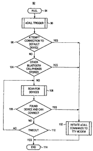
Figure 3 illustrates a process diagram, shown generally at 92, representative
of
exemplary operation of an embodiment of the present invention. After entry at
the null
state 94, a path is taken to the block 96 at which an e-call is triggered
responsive to the
occurrence of a vehicular emergency.
A path is taken to the decision block 98 and at which an attempt is made to
connect
to a default device, i.e., a paired transceiver determined to be in proximity
to the vehicular-
positioned transceiver. If a connection is made, the yes branch is taken to
the block 102,
and an emergency call is initiated, including commands given to a TTY modem.
If, conversely, the attempt to connect to the default device is unsuccessful,
the no
branch is taken from the decision block 98 to the decision block 104. If the
identity of
another paired transceiver is available, the yes branch is again taken to the
block 102 and
the emergency call is initiated. If, conversely, no other identities are
stored, the no branch
is taken from the decision block 104 to the block 106 and a scan is made to
search for
available, paired transceivers.
Then, and as indicated by the decision block 108, a determination is made
whether
an alternate transceiver is located. If so, the yes branch is taken to the
block 102.
Otherwise, the no branch is taken to the block 112, and a determination is
made as to
whether a timeout period has timed out. If not, the no branch is taken back to
the block
106 and the procedure continues. If, conversely, the timeout period has timed
out, the yes
branch is taken to the end block 114. A branch is also taken upon conclusion
of the block
102 to the end block 114.
Figure 4 illustrates a method flow diagram, shown generally at 124,
representative
of the method of operation of an embodiment of the present invention. The
method
facilitates communication of emergency data pursuant to a vehicular emergency.
First, and as indicated by the block 126, a paired transceiver search is
performed
by a vehicular-positioned local transceiver to identify a paired transceiver
in proximity to
11
CA 02585899 2007-04-23
the vehicular-positioned local transceiver. Then, and as indicated by the
block 128, a
paired transceiver is identified responsive to the paired transceiver search.
And, as indicated by the block 132, vehicular emergency indicia is provided to
the
vehicular-positioned transceiver upon occurrence of the vehicular emergency.
Then, and
as indicated by the block 134, the vehicular emergency indicia is sent to the
paired
transceiver for forwarding on to a public safety access point.
Thereby, upon occurrence of a vehicular emergency, a report of the vehicular
emergency is automatically made, taking advantage of the availability of a
mobile station
positioned in proximity to the vehicle at which the vehicular emergency has
occurred.
The previous descriptions are of preferred examples for implementing the
invention, and the scope of the invention should not necessarily be limited by
this
description. The scope of the present invention is defined by the following
claims.
12