Note: Descriptions are shown in the official language in which they were submitted.
CA 02585941 2012-11-26
MULTIPLE CHANNEL WIRELESS COMMUNICATION SYSTEM
[0001] BACKGROUND OF THE INVENTION
1. Field of the Invention
[0002] This invention relates to wireless communication systems, and more
particularly to wireless audio and video systems for providing a plurality of
selectable
audio-video signals from one or more sources to one or more listeners in an
automobile,
airplane, or building.
2. Description of the Prior Art
[0003] Wireless audio systems currently known and available generally
include an
audio source such as a tuner transmitting a signal to one or more wireless
headphones,
wherein the signal carries a single stereo channel of audio data. To select a
different
channel of audio data, someone must operate the tuner to transmit the newly
desired
channel, at which point all wireless headphones receiving the signal will
begin reproducing
the new channel.
[0004] Dual-channel systems are currently known. For instance, the Two-
Channel
Automotive Infrared Headphone System marketed by Unwired Technology LLC
provides
an infrared transmitter that may be connected to two stereo sources and that
will transmit a
different IR signal for each channel. Wireless headphones are provided with a
channel AIB
selector switch to allow the user of the headphone to select among the two
channels. This
system requires two separate stereo sources, and relies on lR LEDs of
different frequencies
(i.e. color) the differentiate between the two channels of audio. This system
also requires
installation of the transmitter at a location where the two signals being
broadcast may be
received at any location within the vehicle.
CA 02585941 2012-11-26
2
[0005] Wireless video systems are also known.
[0006] What is needed is an improved wireless communication system
including
one or more wireless reception devices such as headphones, wherein the system
offers
multiple channels of audio and video signals, and other data, for individual
selection
therebetween by each respective reception device. The system should occupy a
minimum
of space within the home or vehicle, and should ideally be flexible enough to
allow both
analog and digital communications and minimize interference between different
signals
transmitted concurrently.
SUMMARY OF THE INVENTION
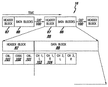
[0007] A wireless audio distribution system may have a wireless
transmitter,
responsive to a plurality of audio input channels, for transmitting signals
carrying the
audio, a receiver, responsive to the transmitted signals for selecting one or
more of the
audio input channels to be reproduced in accordance with local setting
selectors at the
receiver. An additional audio source, such as a microphone, can be selectively
used by for
example the driver to talk on the cell phone or to make announcements to
passengers via
the wireless audio distribution system in accordance with a master settings
selector which
may be used to override local settings such as audio channel or volume
selection.
[0007a] In a further aspect, the present invention provides a wireless
audio
distribution system, comprising: a signal processor combining a plurality of
pairs of stereo
audio inputs and control codes into a serial digital bitstream; a transmitter
for wirelessly
transmitting the serial digital bitstream; a plurality of wireless headset
receivers responsive
to the transmitted serial bitstream to each selectively produce one of the
pairs of stereo
audio therefrom in accordance with the control codes; a local setting selector
for causing
each receiver to produce one of the pairs of stereo audio inputs in the serial
digital
bitstream selected by the local setting selector; and a master settings
selector for selectively
overriding the operation of the local setting selector to cause the wireless
headset receivers
CA 02585941 2012-11-26
. .
2a
to produce one of the pairs of stereo audio related to a different pair of
stereo audio inputs
not selected by the local settings selector.
[0007b] In a still further aspect, the present invention provides
wireless audio
distribution system, comprising: a signal processor combining a plurality of
pairs of stereo
audio inputs and control codes into a serial digital bitstream; a transmitter
for wirelessly
transmitting the serial digital bitstream; a plurality of receivers responsive
to the wirelessly
transmitted serial bitstream to each selectively produce one of the pairs of
stereo audio
therefrom in accordance with the control' codes; a local setting selector
operable to cause
each receiver to produce one of the pairs of stereo audio inputs; and a master
settings
selector for causing override control codes to be included in the digital
bitstream for
overriding the operation of said local setting selector.
[0008] These and other features and advantages will become
further apparent from
the detailed description and accompanying figures that follow. In the figures
and
description, numerals indicate the various features, like numerals referring
to like features
throughout both the drawings and the description.
BRIEF DESCRIPTION OF THE DRAWINGS
[0009] Fig. 1 is a block diagram of wireless headphone system.
[0010] Fig. 2 is a block diagram of wireless headphone system 10
using an analog
signal combining configuration.
[0011] Fig. 3 is a block diagram of one embodiment of a data
stream format used
in a wireless headphone system, such as wireless headphone system 10 depicted
in Figs. 1
and 2.
[0012] Fig. 4 is a block diagram schematic of one embodiment of a
receiver or
headset unit, such as headset receiver unit 14 depicted in Fig. 1.
CA 02585941 2007-04-25
WO 2006/052772 PCT/US2005/040069
- 3 -
[0013] Fig. 5 includes top and front views of one embodiment of multi-
channel
headphones for use in system 10.
[0014] Fig. 6 depicts a functional block diagram of transmitter apparatus
500.
[0015] Fig. 7 depicts a hardware block diagram of encoder 626 of
transmitter apparatus
500 of Fig. 6.
[0016] Fig. 8 is a functional block diagram of clock and clock phasing
circuitry 628 of
transmitter apparatus 500.
[0017] Fig. 9 is a functional block diagram of input audio conversion
module 622 of
transmitter apparatus 500.
[0018] Fig. 10 is a functional block diagram of TR module emitter 634 of
transmitter
apparatus 500.
[0019] Fig. 11 depicts a configuration of transmission data input buffers
for use with
transmitter apparatus 500.
[0020] Fig. 12 depicts a digital data transmission scheme, that may be used
with
transmitter apparatus 500.
[0021] Fig. 13 depicts a functional block diagram of receiver apparatus or
headset unit
700, that may be used in conjunction with a transmitter apparatus such as
transmitter
apparatus 500.
[0022] Fig. 14 is a functional block diagram of primary receiver 702 of
receiver apparatus
700.
[0023] Fig. 15 is a functional block diagram of IR receiver 714 of receiver
apparatus 700.
[0024] Fig. 16 is a functional block diagram of data clock recovery circuit
716 of receiver
apparatus 700.
[0025] Fig. 17 is a functional block diagram of DAC and audio amplifier
module 722 of
receiver apparatus 700.
[0026] Fig. 18 is a functional block diagram of secondary receiver 704 of
receiver
apparatus 700.
[0027] Fig. 19 is a diagram of a vehicle 800 equipped with communication
system 801.
CA 02585941 2007-04-25
WO 2006/052772 PCT/US2005/040069
- 4 -
[0028] Fig. 20 is a diagram of another vehicle 800 equipped with
communication system
801 having additional features over that shown in Fig. 19.
[0029] Fig. 21 is a diagram of vehicle 900 equipped with communication
system 901.
[0030] Fig. 22 is a diagram of a vehicle 988 equipped with a wireless
communication
system 991; and
[0031] Fig. 23 is a diagram of a building 1010 equipped with a wireless
communication
system 1000.
[0032] Fig. 24 is a schematic diagram of an alternate configuration in
which separate
wireless receiver/transmitters separately communicate with separate headset
receivers which
may include transmitters.
[0033] Fig. 25 is a schematic diagram of a further embodiment in which one
or more
wireless receiver/transmitters may be positioned behind a vehicle headliner
transparent to the
radiation used in the wireless system.
[0034] Fig. 26 is a diagram of a wireless computer speaker or headphone
system.
[0035] Fig. 27 is a diagram of a wireless audio distribution system
including a portable
audio source.
[0036] Fig. 28 is a block diagram of an alternate configuration in which an
RF receiver is
inserted between audio sources to cause audio received from an RF source to be
played on the
wireless headphones and a master volume setting may be used to override local
volume
settings in selected receivers
DETAILED DESCRIPTION OF THE INVENTION
[0037] Referring to Fig. 1, one embodiment of a wireless communication
system
disclosed is wireless headphone system 10 that includes transmitter subsystem
12 that
communicates with headset unit 14 via infra-red (IR) or radio frequency (RF)
signals 16,
preferably a formatted digital bit stream including multi-channel digitized
audio data,
calibration data as well as code or control data. The data being transmitted
and received may
comply with, or be compatible with, an industry standard for IR data
communications such as
the Infra Red Data Association or IRDA.
CA 02585941 2007-04-25
WO 2006/052772 PCT/US2005/040069
- 5 -
[0038] Transmitter subsystem 12 IR. transmitter section 18 including IR
transmitter 20,
such as an infra-red light emitting diode or LED, driven by an appropriate IR
transmitter
driver 22 receiving digitized audio data from one or more digital signal
processors, or DSPs,
such as DSP encoder and controller 24, 27, 28 and/or 30. The digital data
stream provided by
IR transmitter section 18 is preferably formatted in accordance with any one
of the proprietary
formats described herein below with reference to Figs. 3, 10 and 16.
[0039] The digitized audio data may be applied to IR transmitter driver 22
from a
plurality of such DSP encoder and controllers that are combined in signal
combiner/
multiplexer 32 that may be separately provided, combined with IR transmitter
section 18 or
combined with DSP encoder and controller 24 in master controller 26. Master
controller 26
may be included within a first audio device, such as audio device 34 as shown,
provided as a
separate unit or included within IR transmitter section 18.
[0040] In a system configuration in which master controller 26 is included
within audio
device 34, wireless headphone system 10 including audio device 34, IR
transmitter section 18
and headset unit 14 may advantageously serve as a base or entry level system
suitable for use
as a single channel wireless headphone system that, in accordance with the
proprietary
formats described herein below with regard to Figs. 3, 10 and 16 may be easily
upgraded for
use as a multi-channel wireless headphone system. For illustrative purposes,
audio device 34
is depicted in Fig. 1 as including audio stage 36, having first and second
audio sources such as
line 1 source 38 and line 2 source 40 each connected to stereo processing
circuitry such as
stereo channel 1 circuitry 42, the output of which is applied to master
controller 26. Audio
device 34 thereby represents any audio, video or data source including mono
and stereo
radios, CD and cassette players, mini-disc players, as well as the audio
portions of electronic
devices that provide other types of signals such as computers, television
sets, DVD players
and the like.
[0041] Whether included as part of an initial installation, or later
upgraded, a second
audio source, such as MP3, WMA, or other digital audio, format player 44, may
be included
within wireless headphone system 10 to provide a second channel of stereo
audio signals. In
particular, MP3 player 44 may conveniently be represented by audio stage 46
that provides
line 3 source 48 and line 4 source 50 to stereo channel circuitry 52, the
output of which may
be a line out, speaker out or headphone out port. As shown in Fig. 1, the
output of stereo
CA 02585941 2007-04-25
WO 2006/052772 PCT/US2005/040069
- 6 -
channel circuitry 52 may be applied to DSP encoder and controller 27 for
combining in signal
combiner/multiplexer 32 of master controller 26 included within audio device
34. In this
manner, an unmodified conventional stereo audio source such as MP3 player 44
may be
added to wireless headphone system 10 by use of an add on DSP device such as
DSP encoder
and controller 27.
[0042] Alternately, a DSP device included within an audio source for other
purposes, such
as related to the production of a digitized audio signal, may be programmed to
provide the
control and formatting required for providing an additional channel of data
for wireless
headphone system 10. In particular, new unit add in device 54 is shown as an
exemplar of an
audio source in which an included DSP has been programmed for compatibility
with the
proprietary format described herein below with regard to Fig. 3. Device 54
generally includes
line 5 source 56 as well as line 6 source 58, both connected through stereo
channel circuitry
60 to DSP encoder and controller 28 for application to signal
combiner/multiplexer 32.
[0043] Similarly, an analog audio device may be included in wireless
headphone system
by use of a legacy adapter, such as legacy adapter 62. Legacy adapter 62 is
illustrated as
including line 7 analog audio input 64 and line 8 analog audio input 66 both
connected to
stereo channel circuitry 68 for application to DSP encoder and controller 30.
It should be
noted that any one of the audio inputs designated as lines 1 through 8, may be
paired as stereo
input lines, used singly as separate monaural inputs, or in any other
convenient combinations
of stereo and mono inputs or as part of a more complex audio format, such as a
home theater
5.1 or 7.1 system. Any one or more of lines 1 through 8 may also be used to
transmit non-
audio data, as described in more detail elsewhere herein.
[0044] As depicted in Fig. 1, wireless headphone system 10 may include one
or more
digital audio sources and may also include one or more analog audio sources.
As shown,
transmitter subsystem 12 may include a single digital signal combiner, such as
signal
combiner/multiplexer 32, fed by digital signals from each of a plurality of
DSPs, such as DSP
encoder and controllers 24, 27, 28 and 30. An alternate configuration of
transmitter
subsystem 12 using analog signal inputs will be described below in greater
detail with respect
to Fig. 2.
[0045] Still referring to Fig. 1, IR. transmitter 20 in IR. transmitter
section 18 produces a
digital bit stream of IR data, designated as lR signals 16, from a convenient
location having a
CA 02585941 2007-04-25
WO 2006/052772 PCT/US2005/040069
- 7 -
direct line of sight path to 1R receiver 70 in headset receiver unit 14. In a
home theater
application, IR transmitter 20 might conveniently be located at the top of a
TV cabinet having
a clear view of the room in which the listener will be located. In a vehicular
application, IR.
transmitter 20 could be located in a dome light in the center of the passenger
compal tinent, or
may be a separate component mounted at a desirable and practicable location
(such as near
the dome light). In a larger area in which multiple headset receiver units 14
are to be driven
by the same IR transmitter 20, IR transmitter section 18 may include a
plurality of IR
transmitters 20 each conveniently located to have a direct line of sight path
to one or more
headset receiver units 14. In other embodiments, as described elsewhere with
regard to Fig.
17, IR. transmission repeaters may be provided to relay the digital bit stream
transmitted by a
single transmitter 20 over longer distances or around obstacles that may
otherwise block the
direct line(s) of sight from transmitter 20 to any one or more of headset
receiver units 14.
[0046] In many applications, the output of IR receiver 70 may conveniently
be processed
by IR received signal processor 72. In either event, after being received, IR
signals 16 are
then applied to decoder 74, containing a clock, de-multiplexer, and
controller, for processing
to provide separate digital signals for stereo channels 1-4 to be applied to
DSP 76 for
processing. DSP 76 may conveniently be a multiplexed DSP so that only a single
DSP unit is
required. Alternately, a plurality of DSP units or sub units may be provided.
[0047] The stereo audio channels 1-4 may conveniently each be processed as
individual
left and right channels, resulting in channels 1L, 2R, 2L, 2R, 3L, 3R, 4L and
4R as shown. It
should be noted, as discussed above that each of these audio channels may be
used as a single
monaural audio, or data channel, or combined as shown herein to form a sub-
plurality of
stereo channels. The resultant audio channels are then made available to
switching selector
78 for selective application to wireless headphone headset earphones,
generally designated as
headphones 80.
[0048] In general, switching selector 78 may be conveniently used by the
listener to select
one of stereo channels 1-4 to be applied to headphones 80. Alternately, one or
more of the
stereo channels can be used to provide one or two monaural channels that may
be selected by
the listener, or in specific circumstances automatically selected upon the
occurrence of a
particular event. In the event headphones 80 are equipped to receive four (or
any other
number of) stereo audio channels, but a lesser number of channels are
available for
CA 02585941 2007-04-25
WO 2006/052772 PCT/US2005/040069
- 8 -
transmission by audio device 34, the number of actual channels being
transmitted may be
incorporated into the digital bit stream of signals 16, and the headphones may
then allow a
user to select only those channels that are available (e.g. if only two
channels are being
transmitted, the user would only be able to toggle between these two channels,
without having
to pass through two or more "dead" channels).
[0049] For example, switching selector 78 may be configured to permit the
listener to
select one of three stereo channels, such as channels 1-3, while stereo
channel 4L may be used
to provide a monaural telephone channel and channel 4R may be used to provide
an audio
signal such as a front door monitor or a baby monitor. In the case of a baby
monitor, for
example, switching selector 78 may be configured to automatically override the
listener's
selection of one of the stereo channels to select the baby monitor audio
whenever the audio
level in the baby monitor channel exceeds a preset level. Further, a fixed or
adjustable time
period after the audio level in the baby monitor channel no longer exceeds the
preset level,
switching selector 78 may be configured to automatically return to the stereo
channel earlier
selected by the listener.
[0050] Alternately, stereo channels 1-3 may be utilized to provide an audio
format, such
as the 5.1 format used for home and professional theaters. In this type of
format, a first stereo
channel is used to provide a front stereo sound source located left and right
of the video being
displayed. Similarly, a second stereo channel may be used to provide a rear
stereo sound
source located left and right behind the listener. A so-called fifth channel
may be a monaural
channel providing a non-stereo sound source located at a center position
between the left and
right front stereo sources. A further monaural channel, representing the so-
called ".1"
channel, may conveniently be a low frequency woofer or subwoofer channel whose
actual
location may not be very critical as a result of the lower audio frequencies
being presented.
Similarly, stereo channels 1-4 may be utilized to provide audio in the so-
called 7.1 audio
format.
[0051] Headphones 80 may conveniently be a pair of headphones speakers
mounted for
convenient positioning adjacent the listener's ears, particularly for use with
wireless
headphone system 10 configured for permitting user or automatic or override
selection of a
plurality of stereo or monaural channels. Headphones 80 may be used in this
configuration to
present audio to the listener in a format, such as the 5.1 format, by
synthesis. For example,
CA 02585941 2007-04-25
WO 2006/052772 PCT/US2005/040069
- 9 -
the center channel of the 5.1 format may be synthesized by combining portions
of the front
left and right channels.
[0052] Alternately, as described below with respect to Fig. 5, alternate
configurations of
headphones 80 may be used to provide a more desirable rendition of a
particular format by
providing a plurality of pairs of headphone speakers mounted in appropriate
positions
adjacent the listener's ears. For example, a first pair of speakers may be
positioned in a
forward position to reproduce the front left and right channels and to
synthesize the center
channel, a second pair of speakers may be positioned in a rearward position to
reproduce the
rear left and right channels, with a resonant chamber mounted to a headband
supporting the
speakers is used to provide the subwoofer (.1) channel.
[0053] Referring now again to Fig. 1, decoder 74 may also be used to
produce control
signals used for providing additional functions. For example, control signals
may be
incorporated into the digital bit stream transmitted by audio device 34 for
error checking,
power saving, automatic channel selection, and other features as described
elsewhere herein.
In addition to audio signals provided to DSP 76, decoder 74 may also be used
to provide
power control signal 82 for application to battery system 84. In particular,
in response to the
decoding of a code contained in the proprietary formats discussed elsewhere,
decoder 74 may
provide a signal, such as power control signal 82, maintaining the application
of battery
power from battery system 84 to wireless headphone system 10. Thereafter, when
the coded
signal has not been received for an appropriate time period, battery power
would cease to be
applied to system 10 to provide an automatic auto-off feature that turns off
system 10 to
preserve battery power when the sources of audio signals, or at least the
formatted signals, are
no longer present. This feature can conveniently be used in an application in
which system 10
is used in a car. When the ignition of the car has been turned off, the power
applied to
headset receiver unit 14 from battery system 84 is stopped in order to
preserve battery life.
As discussed elsewhere, the automatic auto-off feature may also be invoked
when an error
checking feature detects a predetermined number of errors.
[0054] Referring now to Fig. 2, in an alternative embodiment, transmitter
subsystem 13
may be configured with a single DSP, for digitizing audio signals, that is
programmed to
provide signal combining and format control functions. In particular, the
input to IR.
transmitter section 18 may be provided directly by a properly configured DSP
encoder and
CA 02585941 2007-04-25
WO 2006/052772 PCT/US2005/040069
- 10 -
controller 24 that receives as its inputs, the analog audio signal pairs from
stereo channels 1,
2, 3 and 4 provided by stereo integrated circuits, or ICs, 42, 52, 60 and 68,
respectively. As
alternatives to the use of a DSP, any practicable means for performing the
functions herein
described, including any other electronic circuit such as a gate array or an
ASIC (Application
Specific Integrated Circuit) also may be employed. For ease of understanding,
however, the
term DSP is used throughout this specification.
[0055] The source of stereo inputs for stereo channel circuitry 42 in audio
stage 36 may
conveniently be line 1 source 38 and audio stage 36. The source of stereo
input for stereo
channel circuitry 52 in MP3 player 44 may be line 3 source 48 and line 4
source 50, provided
by audio stage 46. Similarly, the sources of stereo input for stereo channel
circuitry 60 and 68
in new unit add in device 54 and legacy adapter 62 may be line 5 source 56 and
line 6 source
58 as well as line 7 analog audio input 64 and line 8 analog audio input 66,
respectively. It is
important to note that all four stereo sources may be combined to provide the
required audio
signals for a complex format, such as 5.1, or one or more of such stereo
channels can be used
as multiple audio channels.
[0056] Referring now to Fig. 3, the format or structure of IR signals 16 is
shown in
greater detail. IR signals 16 form a bit stream of digital data containing the
digitized audio
data for four stereo channels, as well as various calibration and control
data. In one
embodiment, IR signals 16 are an uncompressed stream of digital data at a
frequency or rate
of at least 10.4 MHz. Pulse position modulation (PPM) encoding is preferably
used. This
encoding increases the power level of pulses actually transmitted, without
substantially
increasing the average power level of the signals being transmitted, by using
the position of
the pulse in time or sequence to convey information or data. This power saving
occurs
because in PPM encoding, the same amount of information carried in a pair of
bits at a first
power level in an unencoded digital bitstream may be conveyed by a single bit
used in one of
four possible bit positions (in the case of four pulse position modulation, or
PPM-4,
encoding). In this way, the power level in the single bit transmitted in pulse
position
encoding can be twice the level of each of the pair of bits in the unencoded
bitstream while
the average power level remains the same.
[0057] As shown in Fig. 3, IR. signals 16 include a plurality of
transmitted signals (or
packets, as described elsewhere herein) 86 separated from each other by gap
100 that may
CA 02585941 2007-04-25
WO 2006/052772 PCT/US2005/040069
- 11 -
conveniently simply be a 16 bit word formed of all zeros. Gap 100 is useful to
convey
clocking information for synchronizing the receiver decoding to the clock rate
of the
transmitter, as described below in greater detail with respect to Fig. 4.
[0058] Transmitted signals or packets 86 may conveniently be partitioned
into two
sections, header section 87 and data section 88, as shown. Data section 88 may
conveniently
be composed of 25 samples of each of the 8 audio data streams included in the
four stereo
signals being processed. For example, data section 88 may include word 103
representing the
sampled digital output or stereo channel 1, left while word 104 represents the
sampled digital
output of stereo channel 1, right, followed by representations of the
remaining 3 stereo
channels. This first described group of 8 digital words represents a single
sample and is
followed by another 24 sets of sequential samples of all 8 audio signals. In
this example, each
data section 88 includes 400 digital words to provide the 25 samples of audio
data. If the data
rate of the analog to digital, or A/D, conversion function included within DSP
encoder and
controller 24 shown in Fig. 1 is 16 bits, the first 8 bit word for each
channel could therefore
represent the high bit portion of each sample while the second 8 bit word
could represent the
low bit portion of the sample.
[0059] Referring now also to Fig. 1, if switching selector 78 is operated
to select a
particular monaural or stereo channel, such as channel 3, left, the known
order of the samples
may be utilized to reduce the energy budget of headset receiver unit 14. In
particular, digital
to analog (D/A) conversions may be performed during each data section 88 only
at the time
required for the selected audio or stereo channels such as channel 3, left. In
this manner,
because the D/A conversions are not being performed for all 8 monaural or 4
stereo channels,
the power consumed by the D/A conversions (that are typically a substantial
portion of the
energy or battery system budget) may be substantially reduced, thereby
extending battery
and/or battery charge, life.
[0060] The organization of data block 92 described herein may easily be
varied in
accordance with other known data transmission techniques, such as interleaving
or block
transmission. Referring specifically to Fig. 3, in one embodiment each
transmitted packet 86
may include header section 87 positioned before data section 88. Each header
section 87 may
include one or more calibration sections 101 and control code sections 102. In
general,
calibration sections 101 may provide timing data, signal magnitude data,
volume and/or
CA 02585941 2007-04-25
WO 2006/052772 PCT/US2005/040069
- 12 -
frequency data as well as control data related, for example, to audio format
or other acoustic
information. Control code sections 102 may include information used for error
detection
and/or correction, automatic channel selection, automatic power-off, and other
features of
system 10. Another preferred embodiment is described elsewhere herein with
reference to
. Fig. 12.
[0061] In particular installations, desired acoustic characteristics or the
actual acoustic
characteristics of the installed location of transmitter subsystem 12 may be
synthesized or
taken into account for the listener. For example, the relative positions
including azimuth and
distance of the various sound sources or speakers to the listener, in a
particular concert hall or
other location, may be represented in the calibration data so that an
appropriate acoustic
experience related to that concert hall may be synthesized for the listener
using headset
receiver unit 14 by adjusting the relative delays between the channels. Such
techniques are
similar to those used to establish particular audio formats such as the 5.1
format.
[0062] Alternately, undesirable acoustic characteristics, such as the high
pitched whine of
an engine, the low pitched rumble of the road or airplane noise, that may
penetrate the
acoustic barrier of headphones 80 may be reduced or eliminated by proper use
of the
calibration data. This synthesis or sound modification may be controlled or
aided by
information in calibration portions or IR. signals 16, such as calibration
sections 101, and/or
controlled or adjusted by the listener by proper operation of switching
selector 78, shown in
Fig. 1.
[0063] Similarly, the acoustic experiences of different types or styles of
headphones 80
may be enhanced or compensated for. Conventional headphone units typically
include a pair
of individual speakers, such as left and right ear speakers 81 and 83 as shown
in Fig. 1. A
more complex version of headphones 80, such as multi-channel headphones 118
described
below in greater detail with respect to Fig. 5, may benefit from calibration
data included in
calibration sections 98.
[0064] Techniques for adjusting the listener's acoustic experience may be
aided by data
within calibration sections 101, and/or by operation of switching selector 78,
as noted above,
and also be controlled, adjusted or affected by the data contained in control
code section 102.
Control code data 102 may also be used for controlling other operations of
system 10, such as
CA 02585941 2007-04-25
WO 2006/052772 PCT/US2005/040069
- 13 -
an auto-off function of battery system 84, error detection and/or correction,
power saving, and
automatic available channel selection.
[0065] Referring now to Fig. 4, 5 and 1, IR data in processed IR. packets
86, such as data
section 88, may conveniently be applied to DSP 76, via decoder 74, for
conversion to analog
audio data. IR data in header section 87 may be further processed by other
circuits,
conveniently included within or associated with decoder 74, for various
purposes.
[0066] For use in an auto-off function, the portion of the IR data
processed by IR received
signal processor 72 including control code section 102 may be applied to code
detector 106 to
detect the existence of a predetermined code or other unique identifier. Upon
detection of the
appropriate code, delay counter 108 may be set to a predetermined delay, such
as 30 seconds.
Upon receipt of another detection of the selected code, delay counter 108 may
then be reset to
the predetermined delay. Upon expiration of the predetermined delay, that is,
upon expiration
of the predetermined delay with recognition of the pre-selected auto-off
control word, a signal
may be sent to kill switch 110 that then sends power control signal 82 to
battery system 84 to
shut off headset unit 14.
[0067] In operation, the above described procedure serves to turn off the
battery power for
headset unit 14 unless an appropriate code signal has been recognized within
the previous 60
seconds. The auto-off function may therefore be configured to turn off battery
power 60
seconds (or any other predetermined period) after the cessation of accurate IR
data
transmissions by transmitter subsystem 12. As described elsewhere, system 10
may
incorporate error detection methods. In such an embodiment, the auto-off
function may also
be configured to turn off battery power after a predetermined number and/or
type of errors has
been detected. This approach provides an advantageous auto-off function that
may be used to
save headset battery power by turning off the headphones a predetermined
period after a
radio, or other transmitter, in an automobile is turned off, perhaps by
turning off the ignition
of the car, or alternatively/ additionally when too many
transmission/reception errors have
degraded audio performance to an unacceptable level. Headset unit 14 may also
be
configured to only power down upon detection of too many errors, wherein all
processing
ceases and is reactivated at predetermined intervals (e.g. 30 seconds) to
receive a
predetermined number of packets 86 and check for errors in these received
packets. Headset
CA 02585941 2007-04-25
WO 2006/052772 PCT/US2005/040069
- 14 -
unit 14 may further be configured to resume full, constant operation after
receiving a
preselected number of packets 86 having no, or below, a preselected number of
errors.
[0068] In an advantageous mode, kill switch 110 may also be used to provide
an auto-on
function in the same manner by maintaining the power applied to ER. received
signal processor
72, delay counter 108 and code detector 106 if the power required thereby is
an acceptable
minimum. Upon activation of an appropriate signal source as part of
transmitter subsystem
12, the predetermined code signal may be detected and power control signal 82
sent to battery
system 84 to turn on the remaining unpowered systems in headset receiver unit
14.
[0069] Referring again to FIGS. 1 and 4, one important task in maintaining
proper
operation of system 10 is to maintain synchronization between the operations,
particularly the
sampling and/or A/D operations of transmitter subsystem 12 and the decoding
and related
operations of headset receiver unit 14. Although synchronization may be
maintained in
several different ways, it has been found to be advantageous particularly for
use in a system
(such as system 10) including a possible plurality of battery powered remote
or receiver units
(such as headset units 14) to synchronize the timing of the operations of
headset receiver units
14 to timing information provided by transmitter subsystem 12 and included
within IR signals
16 to assure that the synchronization was accurately achieved for multiple
receiver units that
may be replaced or moved between automobiles from time to time.
[0070] Referring still to Figs. 4 and 5, IR. data is applied from IR.
received signal
processor 72 to synch detector 112 that may conveniently detect gap 100 by,
for example,
detecting the trailing edge of data section 88 in a particular transmitted
packet 86 and, after an
appropriate pre-selected delay or gap, detect the leading edge of header
section 87 of a
subsequent transmitted packet 86. Simple variations of this sync signal
detection may
alternately be performed by synch detector 112 by combining information
related to the
trailing edge, gap length and/or expected data content such as all l's or all
O's or the like and
the actual or expected length of the gap and/or the leading edge.
[0071] Upon detection of appropriate synchronization data, sync detector
112 may then
maintain appropriate clocking information for headset receiver unit 14 by
adjusting a clock or,
preferably, maintaining synchronization by updating a phase lock loop circuit
(or PLL), such
as PLL 114. The output of PLL 114 may then be applied to DSP 76 for
synchronizing the
decoding and/or sampling of the JR data, for example, by controlling the clock
rate of the D/A
CA 02585941 2007-04-25
WO 2006/052772 PCT/US2005/040069
- 15 -
conversion functions of DSP 76. The resultant synchronized signals are then
applied by
switching selector 78 to headphones 80. Without such synchronization, the
audio quality of
the sounds produced by headphones 80 may be seriously degraded.
[0072] Another function that may be provided by decoder 74 includes
updating the
operation of headset receiver unit 14. In particular, upon recognition of an
appropriate update
code by code detector 106, the data in data section 88 from one or more
subsequent
transmitted signals or packets 86 may be applied by code detector 106 to an
appropriate
memory in headset receiver unit 14, such as.rewritable memory 116. The data
stored in
memory 116 may then be used to control subsequent operations of headset
receiver unit 14
by, for example, decoder 74.
[0073] The update function described above with respect to Fig. 4 may be
used to revise
or update headset receiver unit 14 for operating modes that vary the
processing of data in
multiple channel format, such as variations in the 5.1 or 7.1 audio format.
Other uses of the
update format may be in automatically selecting the language or age
appropriate format used
on various audio channels to control what is provided to a particular
listener.
[0074] For example, system 10 may be used in a museum to provide
information, in audio
format, for one or more exhibits. Before a particular headset receiver unit 14
is provided to,
or rented by, a museum visitor, that headset unit might be programmed by use
of the update
format to provide age appropriate audio for the listener to be using the
headset unit.
[0075] Alternately, the updating may be performed upon rental of a headset
unit to
correspond to the audio services to be provided. A particular headset might be
programmed
to automatically activate upon receipt of an audio signal of a sufficient
magnitude to indicate
proximity to the exhibit to be described. One headset might be programmed to
provide audio
only for exhibits in a certain collection while other headsets might be
programmed to receive
all related audio. This programming or updating may easily be performed at the
time of rental
or other distribution for each headset.
[0076] Another use of the updating or programming function is to permit the
reprogramming of a larger number of headsets at the same time. For example,
continuing to
use the museum exemplar, a paging system, emergency or other notification
system may be
implemented with the upgrade function so that museum patrons with a selected
code in their
CA 02585941 2007-04-25
WO 2006/052772 PCT/US2005/040069
- 16 -
headset, or all such patrons, may be selectively paged or notified of
specified information,
such as museum closing times or the procedure to follow upon declaration of an
emergency
such as a fire. In this way, such information may be provided in real time,
from a simple
telephone or paging interface, by controllably switching the audio produced in
one or more
selected headphones rather than by altering the audio being normally produced.
[0077] Another example of the use of the upgrade function might be to
change codes that
permit operation of the headphones, or related equipment, to prevent stealing
or tampering
with the headphones. Headphones being improperly removed from a listening
chamber, such
as a vehicle, may be programmed to issue a warning, to the listener or to
others, upon passing
through an exit. In order to prevent tampering with the headsets to foil such
operations, the
codes may be randomly or frequently changed.
[0078] further use of the upgrade function is to permit headphone units to
be sold or
provided for use at one level and later upgraded to a higher level of
operation. As one simple
example, multi-channel headphones may be distributed without coding required
to perform
multi channel operation. Such headphones, although desirable for single
channel operation,
may then temporarily or permanently upgraded for higher performance upon
payment of an
appropriate fee.
[0079] Referring now to Fig. 5, top and front views of multi-charmel
headphones 118 use
with system 10 are depicted in which left earphone system 120 and right
earphone system 122
are mounted on head band 124 that is used to position the earphones on the
listener's head.
Each of the earphone systems includes a plurality of speakers, such as front
speaker 126,
center speaker 128 and rear speaker 130 as designated on right earphone system
122 together
with effective aperture 132 and effective audio paths 134.
[0080] The apparent distances along effective audio paths 134 from speakers
126, 128 and
130 to effective aperture 132 in each earphone are controlled to provide the
desired audio
experience so that both the apparent azimuthal direction and distance between
each speaker as
a sound source and the listener is consistent with the desired experience. For
example, audio
provided by speakers 126 and 128 may be provided at slightly different times,
with different
emphasis on the leading and trailing edges of the sounds so that an apparent
spatial
relationship between the sound sources may be synthesized to duplicate the
effect of home
theater formatted performances. Although the spatial relationships for some
types of sounds,
CA 02585941 2007-04-25
WO 2006/052772 PCT/US2005/040069
- 17 -
like high frequency clicks, may be easier to synthesize than for other types
of sounds, the
effect of even partial synthesis of spatial sound relationships in a headset
is startling and
provides an enhanced audio experience.
[0081] In addition to the speakers noted above for use in stereo and
multiple channel
stereo formats, a low frequency, non-directional monaural source, such as sub
woofer 134,
may be advantageously mounted to headband 124 to enhance the user's audio
experience.
[0082] With reference now to Fig. 6, audio transmission device 500 includes
single DSP
600 which may receive four digitized audio input streams 602, 603, 604, 605
multiplexed by
two multiplexers 606, 608 into two signals 610, 612 for input into direct
memory access
(DMA) buffers DMAO 614 and DMA1 616 connected to serial ports 613, 615 of the
DSP
600. Audio streams 602-605 may be digitized by analog-to-digital converters
(ADCs) 618,
619, 620, 621 located for example in audio modules 622, 623, 624, 625 shown in
Fig. 7.
Audio device 34 and MP3 player 44 of Fig. 1 are typical examples of such audio
modules. As
noted above with respect to Fig. 1, audio devices utilizing multiple analog
inputs provided to
a single ADC, as well as multiple digital inputs that are provided directly to
multiplexers such
as multiplexers 606, 608, may be used.
[0083] Referring to Fig. 7, the data multiplexing circuitry of audio
transmission device
500 combines two channels of digitized data 602, 603 and 604, 605 into one
serial data stream
610, 612 respectively. The data stream slots for two differently phased
digital audio stereo
pairs (two stereo pairs) 610, 612 are combined to create one constant digital
data stream 633.
The left/right clocking scheme for the audio modules, described in greater
detail elsewhere
herein, is configured such that two stereo channels (four analog audio input
lines) share one
data line. Outputs 602, 603 and 604, 605 of in-phase ADCs 618, 620 and 619,
621 are
multiplexed with the 90 degrees phase shifted data. The higher ordered
channels (Channels 3
and 4) are clocked 90 degrees out of phase of the lower channels (Channels 1
and 2). This
allows two channels pairs (Channel 1 left and right and channel 3 left and
right) to share a
single data line. Two sets of serial digitized audio data are input to DSP
600. Both odd
numbered channels are on the same serial line and both even numbered channels
are on the
same serial line. Clock and clock phasing circuitry 628 provides the input
data line selection
of multiplexers 606, 608.
CA 02585941 2007-04-25
WO 2006/052772 PCT/US2005/040069
- 18 -
[0084] With continued reference to Fig. 7, DSP 600, together with
multiplexers 606, 608,
may be provided in encoder 626 within transmitter 500. Encoder 626 accepts the
four
digitized audio inputs 602, 603, 604, 605 from audio modules 622, 623, 624,
625 and uses
line driver 631 to send digitized serial data stream 633 to IR. transmitter
module 634 for
transmission to headphones 80.
[0085] Encoder 626 also includes clock and clock phasing circuitry 628,
boot/program
memory 630, and power supply 632. DSP 600 serves as the central control for
the encoder
626 circuitry, including control of all inputs and outputs of audio
transmission device 500. A
clocking divider provided within clocking circuit 628 is activated by DSP 600
to provide
signals to drive the clocks for any audio modules (e.g. ADCs) and audio data
inputs to the
DSP. DSP 600 combines audio data 610, 612 from two serial sources
(multiplexers 606, 608)
and formats the audio data into single serial data stream 633 of data packets
that is provided to
line driver 631 to send to IR transmitter 634. In one embodiment, line driver
631 may be a
differential line driver with an RS485 transceiver, and an inverter may be
used to invert and
buffer data from DSP 600. DSP 600 uses the base 10.24 MHz clock of clocking
circuit 628
multiplied by a phase locked loop (PLL) internal to the DSP. In one embodiment
the DSP
clock speed is 8X MHz, but this may be reduced so as to reduce overall power
consumption
by audio transmission device 500.
[0086] With continued reference to Fig. 7, boot memory 630 stores the
program memory
for DSP 600 (that contains the software controlling the DSP) during shut down.
An 8-bit
serial EEPROM may be used as boot memory 630. Upon power up, the DSP may be
programmed to search external memory circuits for its boot program to load and
commence
executing. Boot memory 630 is attached to multi-channel buffered serial port
615 (McBSP 1)
of DSP 600. In alternative embodiments, the DSP software may be provided in
DSP read-
only-memory (ROM).
[0087] With reference now to Fig. 8, clock and clock phasing circuitry 628
develops all
clocks required by encoder 626 and audio modules 622, 623, 624, 625. Four
separate clocks
are required for the DSP, audio data transfer and audio digitizing. These are
master clock
660, serial clock 661, left/right clock 662 and multiplexer clock 663. Clock
phasing is also
required by multiplexers 606, 608 to multiplex digitized audio input streams
602, 603, 604,
605 as previously described with respect to Fig. 6. Master clock 660 is used
to drive the
CA 02585941 2007-04-25
WO 2006/052772 PCT/US2005/040069
- 19 -
master-synchronizing clock signal for the audio digitizing modules and the
DSP. Master
clock signal 660 is generated from stand-alone crystal oscillator circuit 660
and has buffered
output 661. The master clock frequency is 10.24 MHz, which allows the
derivation of the
serial clock and left/right clock from the master clock. The serial clock is
used to clock each
individual bit of digitized audio input streams 602, 603, 604, 605 from audio
modules 622,
623, 624, 625 into DSP 600. Serial clock signal 661 is derived from the master
clock using
one-fourth clock divider 667 to generate a clocking signal at a frequency of
2.56 MHz.
[0088] The left/right clock is used to clock the Left and Right data words
from digital
audio data streams 610, 612 generated by multiplexers 606, 608 for input to
DSP 600, and to
develop the DSP frame sync. Left/right clock signals 662 are derived from the
master clock
using clock divider 667 to generate a signal at a frequency that is 256 times
slower than the
master clock. Clock phasing circuitry 668 separates the left/right clock into
two phases by
providing a 90-degree phase shift for one of the left/right clocks. This
allows two of the four
audio modules 622, 623, 624, 625 to produce a 90-degree phase shifted output.
The outputs
of the in phase left/right clocked audio module outputs are multiplexed with
the 90 degrees
phase shifted data on one line. Each left/right clock phase serves as a
separate frame sync for
digitized audio input streams 602, 603, 604, 605 from audio modules 622, 623,
624, 625.
[0089] Multiplexer clock 663 is used by the multiplexer logic for toggling
the selected
input data lines to combine the digital audio packets in digitized audio input
streams 602, 603,
604, 605 from audio modules 622, 623, 624, 625. Multiplexer clock signal 663
is also
generated by clock divider 667. DSP clock signal 664 is used to drive DSP 600
and is
generated by converting master clock signal 660 to a lower voltage (e.g. 1.8V
from 3.3V), as
required by the DSP, by buffer/voltage converter 669. Other clocking schemes
may be used
by changing the base crystal oscillator frequency (i.e. the 9.216 MHz base
clock for a 40KHz
left/right clock may be changed to a 11.2896 MHz base clock for a 44.1 KHz
left/right clock).
[0090] Power supply 632 develops all of the required voltages for encoder
626. In one
embodiment, encoder power supply 632 may accept an input voltage range from
+10 VDC to
+18 VDC. Four separate voltages may be used on the transmitter baseboard;
Input voltage
(typically +12VDC), +5VDC, +3.3VDC, and +1.8VDC. Transient protection may be
used to
prevent any surges or transients on the input power line. A voltage supervisor
may also be
used to maintain stability with DSP 600. The unregulated input voltage is used
as the source
CA 02585941 2007-04-25
WO 2006/052772 PCT/US2005/040069
-20 -
voltage for the +5 VDC. A regulated +5 VDC is used to supply IR transmitter
module 634.
Audio modules 622, 623, 624, 625 use +5 VDC for input audio protection and
input audio
level bias. IR transmitter 634 uses +5 VDC for bias control and IR driver
circuit 650.
Regulated +3.3 VDC is used to supply DSP 600 and logic of encoder 626, and is
also
supplied to the audio modules for their ADCs. The +3.3 VDC is developed from
the
regulated +5VDC supply voltage and is monitored by a voltage supervisor. If
the level falls
below 10% of the +3.3 VDC supply, the voltage supervisor may hold DSP 600 in
reset until a
time period such as 200 ms has passed after the voltage has increased above
+3.0 VDC.
Regulated +1.8 VDC is used to supply the DSP core of encoder 626 and is
developed from
the regulated +3.3 VDC supply voltage.
[0091] Referring now to Fig. 9, in one embodiment audio modules 622, 623,
624, 625
may be used to provide digitized audio input streams 602, 603, 604, 605 to DSP
600. The
audio modules may be external or internal plug-in modules to encoder 626 or
may be
incorporated into the encoder. hi an embodiment providing four channels of
audio, four audio
modules may be used with the transmitter baseboard. Each audio module, such as
audio
module 622 shown in Fig. 9. accepts one stereo audio pair (left and tight) of
inputs 638, 639.
Power and the master clock, serial clock, and left/right clock are all
supplied by encoder 626.
Signal conditioning and input protection circuitry may be used to prepare the
signals 638, 639
prior to being digitized and protect the input circuitry against transients.
[0092] Signals 638, 639 may be conditioned separately. DC Bias circuit 640
sets signals
638, 639 to the midrange of the five-volt power supply so as to allow the
input signal to be
symmetric on a DC bias. hi this manner, any clipping that occurs will occur
equally on each
positive and negative peak. Input Surge Protection circuit 641 may be used to
protect the
input circuitry against transients and over voltage conditions. Transient
protection may be
provided by two back-to-back diodes in signal conditioning and input
protection circuit 640 to
shunt any high voltages to power and to ground. Line level inputs may be
limited to two
volts, or some other practicable value, peak to peak. Low pass filter 642 may
be provided to
serve as a prefilter to increase the stopband attenuation of the D/A internal
filter. In one
embodiment, each analog input audio channel frequency is 20 Hz to 18 KHz and
the low pass
filter 642 corner frequency is above 140 KHz so that it has minimal effect on
the band pass of
the audio input.
CA 02585941 2007-04-25
WO 2006/052772 PCT/US2005/040069
- 21 -
[0093] With continued reference to Fig. 9, ADC 643 is used to digitize both
left and right
analog inputs 638, 639. Single serial digital data stream 602 containing both
the left and right
channels is output by ADC 643 to encoder 626. The 10.24 MHz master clock is
used to
develop the timing for ADC 643, and the 2.56 MHz serial data clock is used to
clock the data
from the ADC. The 40 KHz left/right clock is used to frame the data into
distinct audio
samples. Each left and right analog sample may be a 16-bit value.
[0094] With reference now to Fig. 10, IR transmitter or module 634 converts
digital data
stream 633 to lR (Infrared) transmission signals 16. PPM (Pulse Position
Modulation)
encoding is used to increase transmitter power by using a bit position value.
lR transmitter
634 includes line receiver 650 to receive differential R5485 signal 633 from
line driver 631
and transform it into a single ended data stream. The data stream is then
buffered and
transferred to infrared bias and control circuits 650, which drives the light
emitting diode(s)
(LEDs) of emitters 652 and controls the amount of energy transmitted. lR
transmitter 634
includes four infrared bias and control circuits 650 and four respective
emitters 652, with a
25% duty cycle for each emitter 652. Bias control maintains the IR emitter(s)
in a very low
power-on state when a zero bit is sensed in data stream 633 to allow the
direct diode drive to
instantly apply full power to the IR emitter diodes when a positive pulse (one
bit) is sensed.
A sensing resistor is used to monitor the amount of current supplied to the
diodes so that when
the emitter diode driver is pulsed, the bias control maintains a constant
current flow through
the diodes. IR emitters 652 transform digital data stream 633 into pulses of
infrared energy
using any practicable number (e.g. four per IR emitter) of IR emitter diodes.
The bandwidth
of the electrical data pulses are mainly limited by the fundamental frequency
of the square
wave pulses applied to the IR emitter diodes due to the physical
characteristics of the diodes.
In one embodiment, the IR energy may be focused on a center wavelength of 870
nM.
Encoder 626 supplies all power to lR transmitter module 634. +5 VDC is used
for driver and
bias control circuitry 650. In one embodiment, encoder 626 supplies PPM-
encoded digital
data stream 633 to IR transmitter 634 at 11.52 Mb/s.
[0095] Referring now to Fig. 11, MCBSPs 613, 615 and DMAs 614, 616 are used
to
independently gather four stereo (eight mono) channels of data. When either of
the McBSPs
has received a complete 16-bit data word, the respective DMA transfers the
data word into
one of two holding buffers 670, 671 (for DMA1 616) or 672, 673 (for DMAO 614)
for a total
CA 02585941 2007-04-25
WO 2006/052772 PCT/US2005/040069
-22 -
of four holding buffers. Each McBSP 613, 615 uses it's own DMA 614, 616 and
buffer pair
672/673, 670/671 to move and store the digitized data. While one buffer is
being filled, DSP
600 is processing the complementary buffer. Each buffer stores twenty-five
left and twenty-
five right data samples from two different ADCs (for a total of 100 16-bit
samples). Each
word received by each McBSP increments the memory address of the respective
DMA.
When each buffer is full, an interrupt is sent from the respective DMA to DSP
600. DSP 600
resets the DMA address and the other buffer is filled again with a new set of
data. This
process is continuously repeated.
[0096] DSP 600 creates two transmit buffers that are each the size of a
full transmit
packet 86. In one embodiment, 450 (16-bit) words are used in each packet (as
more fully
discussed below). When a packet 86 is first initialized, static header/trailer
values are inserted
in the packet. For the initial packet and subsequent packets, the User
ID/Special
Options/Channel Status (USC) values of control block 96, data offsets, dynamic
header
values, and channel audio data are added to each packet. The USC values
calculated from the
previous packet audio data are preferably used. The audio data is PPM encoded
and placed in
data blocks packet. Once a predetermined number (e.g. twenty-five) of samples
from each
channel have been processed, packet 86 is complete.
[0097] When DSP 600 fills one of the output buffers completely, a
transmission DMA
(DMA2) is enabled. DMA2 then transfers the data in the filled output buffer to
a serial port
(McBSPO) of transmission device 500. McBSPO in turn sends serial data 633 to
line driver
631 to send to lR transmitter 634. Once the Output DMA and McBSP are started,
they
operate continuously. While DSP 600 fills one of the buffers, the other buffer
is emptied by
DMA2 and sent to McBSPO. Synchronization is maintained via the input data.
[0098] DSP 600 handles interrupts from DMAs 614, 616, monitors Special
Options and
Channel Status information as described elsewhere herein, constructs each
individual signal
(or transmission packet) 86, and combines and modulates the audio data and
packet
information. The DMA interrupts serve to inform DSP 600 that the input audio
buffer is full,
at which time the DSP reconfigures the respective DMA to begin filling the
alternate holding
buffer and then begins to process the "full" holding buffer. No interrupt is
used on the output
DMA. Once the output buffer is full, the output DMA is started to commence
filling the other
buffer.
CA 02585941 2007-04-25
WO 2006/052772 PCT/US2005/040069
-23 -
[0099] As more fully described elsewhere herein, Special Options
information may be
used to indicate if audio transmission device 500 is being used in a unique
configuration and
may be provided through hardware switches or hard coded in the firmware.
Special Options
may include, but are not limited to, 5.1 and 7.1 Surround Sound processing. In
one
embodiment, four bits may be used to indicate the status of the Special
Options. Four bits
will provide for up to four user selectable switch(es) or up to fifteen hard
coded Special
Options. The Headphone normal operation may be a reserved option designated as
0000h. =
[0100] When a switch option is used, a minimum of one or more of the
fifteen Special
Options will be unavailable for additional options (i.e. if two switches are
used, only four
additional Special Options may be available. If four switches are used, no
additional Special
Options may be available.) For instance, to utilize a 5.1 or 7.1 Surround
Sound option, a
hardware switch may be used to toggle a bit level on a HPI (Host Port
Interface) of DSP 600.
A one (high) on the HPI may indicate that an option is used. A zero (low) on
the HPI may
indicate normal four-channel operation. DSP 600 may read the HPI port and set
the
appropriate bit in the Special Options value.
[0101] Channel Status information may be used to indicate which stereo
channels (left
and right channels) contain active audio data. The amplitude of the digital
audio data may
determine whether a stereo channel is active or inactive. If active audio is
not detected on a
stereo channel, the Channel Status can be flagged in the outgoing packets as
OFF (zero). If
active audio is sensed on a stereo channel the Channel Status can be flagged
in the outgoing
packets as ON (one).
[0102] In one embodiment, to determine if a stereo channel is active, the
absolute values
for each set of the four stereo channel data samples are accumulated. Twenty-
five samples
(the number of individual channel data samples in one packet) of each left
channel and each
right channel are combined and accumulated. If the sum of the stereo channel
samples
exceeds the audio threshold, the Channel Status may be tagged as active. If
the total of the
stereo channel samples does not exceed the audio threshold, the Channel Status
may be
tagged as inactive. Four bits (one for each stereo channel) may be used to
indicate the stereo
Channel Status and preferably are updated each time a packet is created.
[0103] Referring to Fig. 12, an embodiment for encoding the four channels
into individual
signals or transmission packets 86 is shown to partition each signal 86 into
header section 87
CA 02585941 2007-04-25
WO 2006/052772 PCT/US2005/040069
-24 -
and data section 88. Header section 87 contains all of the information for
receiver 700
(detailed herein below) to sense, synchronize and verify the start of a valid
transmission
packet 86. In one embodiment, the header section includes Preamble,
Terminator, and Gap
values that are not PPM encoded, and further includes Product Identifier and
Data Offset
values that are PPM encoded.
[0104] Gap value 90 may be a 32-bit (double word) value used by receiver
700 to sense
header section 87 and synchronize with transmission packet 86. Gap 90 may be
composed of
a Sense Gap, a Trigger Gap, and a Sync Gap. The Gap is preferably not PPM
encoded and is
a static value that is never changed. The first part of Gap 90 is the Sense
Gap, which contains
seven leading zeros. These bits are used by receiver 700 to recognize the
beginning of the
Gap period. The second part of Gap 90 is the Trigger Gap, which contains
alternating one
and zero bits. These bits are by receiver 700 to stabilize the clock recovery
circuitry over the
Gap period. The third part of the Gap is the Sync Gap, which contains three
zero bits. These
bits are used by receiver 700 to mark the beginning of each transmission
packet 86.
[0105] Preamble PRE may consist of a predetermined number of equal values
(e.g.
AAAA hexadecimal) to further enable synchronization of receiver 700 with
transmitter 500.
The preamble consists of two separate 16-bit (double word) values 89, 91 and
are used by
receiver 700 to identify the start of each packet 86. Preamble 1 word 89 is
also used to assist
in stabilizing the clock recovery circuitry. The Preamble is not PPM encoded
and may be a
static value that is never changed. Preamble 1 word 89 is preferably placed at
the start of
packet 86 and preamble 2 word 91 preferably follows Gap 90: Preamble words 1
and 2 are
composed of alternating ones and zeros (AAAAh). The first "one" bit of the
Preamble 2 word
91 may signal the start of the particular packet 86.
[0106] Following the Preamble 2 word 91 is predetermined code or unique
identifier ID
(PD) 92, which may be selected to uniquely identify transmitter 500 to
receiver 700. PD 92
is preferably PPM encoded and is a static value that does not change. This
feature may be
used, for example, to prepare headphones that may only be used in a car, or
limited to use
with a particular make of car, or with a particular make of transmitter. Thus,
for headphones
used in a museum wherein visitors rent the headphones, the receivers in the
headphones may
be programmed to become operation only upon detection of a unique identifier
ID that is
transmitted only by transmitters 500 installed in the museum. This feature
would discourage
CA 02585941 2007-04-25
WO 2006/052772 PCT/US2005/040069
-25 -
a visitor from misappropriating the headphones because the headphones would
simply not be
functional anywhere outside of the museum. This feature may further be used to
control
quality of after market accessories by an OEM. For instance, a vehicle
manufacturer or a car
audio system manufacturer may install transmitters in their equipment but
control the
licensing/distribution of the unique ID transmitted by their equipment to
those accessory
(headphones, loudspeakers, etc.) manufacturers that meet the OEM's particular
requirements.
[0107] Following ND 92 is data offset value (DO) 93 followed by offset
portion 94, the
final portion of header section 87. Offset value 93 indicates the length of
(i.e. number of
words in) offset portion 94 and data filler portion 97, and may be a fixed
value that is constant
and equal in each transmitted signal or packet 86, or alternatively may be
dynamically varied,
either randomly or according to a predetermined scheme. Varying the length of
the offset
portion from signal to signal may help avoid fixed-frequency transmission
and/or reception
errors and reduce burst noise effects. Offset portion 94 and data filler
portion 97 together
preferably contain the same number of words (e.g. 30), and thereby allow the
random
placement of data section within a particular packet 86 while maintaining a
constant overall
length for all packets. Offset portion 94 serves to space unique PD 92 from
data section 88
and may contain various data. This data may be unused and thus composed of all
random
values, or all zero values, to be discarded or ignored by receiver 700.
Alternatively, offset
portion 94 may contain data used for error detection and/or error correction,
such as values
indicative of the audio data or properties of the audio data contained in data
section 88.
[0108] Data section 88 is formed by interleaving data blocks 95 with
control blocks 96.
In one embodiment data block 95 consist of 5 samples of 4 channels of left and
right encoded
16-bit values (1 word) of audio information, for a total of 80 PPM-encoded
words. Data
blocks 95 may consist of any other number of words. Furthermore, the data
blocks in each
signal 86 transmitted by transmitter 500 do not have to contain equal numbers
of words but
rather may each contain a number of words that varies from signal to signal,
either randomly
or according to a predetermined scheme. Consecutive data blocks 95 within a
single packet
86 may also vary in length. Additionally, consecutive packets 86 may contain
varying
numbers of data blocks 95 in their data sections 88. Indicators representing,
e.g., the number
of data blocks and the number of words contained in each data block may be
included in
CA 02585941 2007-04-25
WO 2006/052772 PCT/US2005/040069
-26 -
header block 87 of each packet 86, such as in offset portion 94, to enable
transmitter 700 to
properly process the data contained in each packet 86.
[0109] Control block 96 follows each data block 95, and in one embodiment
includes the
Special Options and Channel Status information discussed previously, as well
as a
predetermined code or unique identifier User ID. As described elsewhere
herein, User ID
may be a value used for error detection, such as by comparing a User ID value
contained in
header 87 with each successive User ID value encountered in subsequent control
blocks 96.
If the values of User ID throughout a packet 86 are not identical, the packet
may be discarded
as a bad packet and the audio output of the headphones may be disabled after a
predetermined
number of sequential bad packets has been received. The User ID may further be
used to
differentiate between various transmission devices 500 such that, for
instance, a receiver 700
programmed for use with a transmission device installed in a particular
manufacturer's
automobile will not be useable with the transmission devices in any other
manufacturers
automobiles or in a building such as a museum or a private home (as further
detailed
elsewhere herein). Channel Status information may be used to control the
channel selection
switch on receiver 700 to only allow selection of an active channel, and to
minimize power
consumption by powering down the receiver DSP to avoid processing data words
in each
packet 86 that are associated with an inactive channel, as more fully
described elsewhere in
the specification.
[0110] At the end of data section 88 is trailer 99 which may include data
filler 97 and end
block or terminator block (TRM) 98. TRM 98 may preferably a 16-bit (single
word) value
and may be used by receiver 700 to allow a brief amount of time to reconfigure
the McBSP
parameters and prepare for a new packet 86. TRM 98 may also be used to assist
in stabilizing
the receiver 700 hardware clock recovery over the GAP 90 period, and may also
contain data
for error detection and/or correction, as discussed elsewhere. TRM 98 is
preferably not PPM
encoded and is a static value preferably composed of alternating ones and
zeros (AAAAh).
[0111] With reference now to Fig. 13, receiver apparatus or headset unit
700 has two
separate sections to enable omni-directivity of reception and to more evenly
distribute the
circuitry of the receiver throughout the enclosure of headphones 80. The main
section of the
receiver is primary receiver 702. The secondary module is secondary receiver
704. Both
primary receiver 702 and secondary receiver 704 contain an IR receiver
preamplifier. In one
CA 02585941 2007-04-25
WO 2006/052772 PCT/US2005/040069
-27 -
embodiment, primary receiver 702 may contain the bulk of the receiver
circuitry and
secondary receiver 702 may be used as a supplementary preamplifier for IR
signal 16 when
the primary receiver IR receiver is not within line of sight of the
transmitted IR signal due to
the orientation or location of the listener wearing headphones 80.
[0112] Referring to Fig. 14, primary receiver 702 contains receiver DSP
710, IR
receiver/AGC 714, data clock recovery circuit 716, D/A converter (DAC) and
audio amplifier
circuit 722, user selectable switches and indicators control circuit 718,
boot/program memory
730, and power supply and voltage supervisor circuit 740. DSP 710 serves as
the central
control for the receiver 700 circuitry and controls all of the inputs and
outputs of the receiver.
The IR data packet is received by DSP 710 in single serial stream 712 from IR.
receiver 714.
The start of IR data stream 712 creates the frame synchronization for the
incoming data
packet. Clock recovery circuit 716 develops the IR data clock used to sample
the IR data.
The DSP serial port completes clocking for the 16-bit DAC. The master clock
for the 16-bit
D/A converter is developed from an additional serial port.
[0113] External switches and indicators 719 may include switches to allow
the listener to
access functions such as select the desired channel and adjust the audio
volume. LED
indicators may be provided to be driven by DSP 710 to indicate whether power
is supplied to
the receiver and the selected channel. Control circuit 718 interfaces external
switches and
indicators 719 with DSP 710, providing input from the switches to the DSP and
controlling
the indicators as dictated by the DSP.
[0114] The base clocking for DSP 710 may be developed from clock recovery
circuit 716.
The input clock to DSP 710 is multiplied by a PLL internal to the DSP. The DSP
clock speed
may be 8X MHz, and may be reduced to minimize overall power consumption by
receiver
700. DSP 710 can also disable the switching power supply on secondary receiver
704 via a
transistor and a flip-flop. If the software does not detect a valid signal in
a set amount of time,
the DSP can disable the switching power supply and remove power from the
receiver, as
detailed elsewhere herein.
[0115] Referring now to Fig. 15, IR. Receiver/AGC 714 is used to transform
and amplify
the infrared data contained in received signal 16. IR Receiver/AGC 714 also
controls the
amplification and develops digital data stream 712 for DSP 710 and data clock
recovery
circuit 716. The usable distance for the TR. receiver is dependent on
variables such as
CA 02585941 2007-04-25
WO 2006/052772 PCT/US2005/040069
-28 -
transmitter 500 power and ambient lighting conditions. In one embodiment, the
overall gain
of IR Receiver/AGC 714 may be approximately 70 dB.
[0116] With continued reference to Fig. 15, IR receiver/AGC circuit 714
contains
preamplifier 770, final amplifier 771, data squaring stage (or data slicer)
772, and AGC
(Automatic Gain Control) circuit 773. IR preamplifier 770 transforms optical
signal 16 into
an electrical signal and provides the first stage of amplification. The IR
preamplifier is
composed of three separate amplifiers. The first amplifier is composed of four
IR photo
detector diodes and a transimpedance amplifier. In one embodiment, combined
wide viewing
angle photo diodes may produce better than 120 degrees of horizontal axis
reception and 180
degrees of vertical axis reception. A daylight filter may be incorporated into
the photo
detector diode that, together with inductive transimpedance amplifier feed
back, minimizes
the DC bias effect of ambient lighting. When IR signal 16 is transmitted, a
current pulse
proportional to the strength of the IR signal is generated in the photo
detector diodes. The
strength of the received IR signal is dependent on the distance from the
transmitted IR source.
[0117] The current pulse from the photo diodes is applied directly to the
transimpedance
amplifier. The transimpedance amplifier senses the rising and falling edges of
the current
pulse from the photo detector diodes and converts each pulse into a voltage
"cycle." The
second amplifier is a basic voltage amplifier. The output of the second stage
is controlled by
AGC circuit 773. The third amplifier is also a basic voltage amplifier. The
output of the third
stage of preamplifier 770 is fed the input of final amplifier stage 771 and
AGC 773.
[0118] Final amplifier stage 771 is used to further increase the gain of
received IR signal
16 and also serves as a combiner for Headphone ¨ Left and Headphone ¨ Right
preamplifiers
750, 770. Final amplifier 771 is composed of two basic voltage amplifiers.
Each of the two
stages of amplification increases the gain of the received IR signal. The
input signal to the
final amplifier is also controlled by the second stage of AGC 773, as
described below. The
output of the final amplifier stage is fed to AGC 773 and data squaring stage
772.
[0119] AGC 773 controls the amplified IR signal level. The AGC circuitry
may be
composed of one amplifier and three separate control transistors. The three
separate control
transistors comprise two levels of AGC control. The first level of AGC control
uses two
AGC control transistors (one for each stage) and is performed after the first
voltage amplifier
in both the Headphone ¨ Left and Headphone ¨ Right preamplifier stages 750,
770. The
CA 02585941 2007-04-25
WO 2006/052772 PCT/US2005/040069
-29 -
second level of AGC control occurs at the junction of both of preamplifier
750, 770 output
stages and the input to final amplifier stage 771. To develop the AGC DC bias
voltage, the
positive peaks of the IR. signal from the final amplifier stage output are
rectified and filtered.
The DC signal is amplified by an operational amplifier. The value of the
amplified DC
voltage is dependent on the received signal strength (i.e. proportional to the
distance from IR
emitters 652 of transmission device 500). The AGC transistor resistance is
controlled by the
DC bias and is dependent on the received signal strength. When the signal
strength increases,
the bias on the AGC transistors increases and the signal is further
attenuated. AGC 773 thus
produces a stable analog signal for data squaring stage 772.
[0120] Data squaring stage 772 produces a digitized bi-level ¨ square wave
(i.e.
composed of ones and zeros) from the analog IR signal. The input from the data
squaring
stage is received from the output of final amplifier stage 771. The data
squaring stage
compares the final amplifier 771 output voltage "cycle" to a positive and
negative threshold
level. When the positive peak of the final amplifier output exceeds the
positive threshold
level, a high pulse (one bit) is developed. When the negative peak exceeds the
negative
threshold level, a low pulse (zero bit) is developed. Hysteresis is accounted
for to prevent
noise from erratically changing the output levels. The output of data squaring
stage 772 is
sent to clock recovery circuit 716 and as IR data input 720 to DSP 710.
[0121] Data clock recovery circuit 716 is used to reproduce the data clock
used by
transmitter 500. In one embodiment of receiver 700, the data clock recovery
circuit contains
an edge detector and a PLL (Phase Lock Loop). The data clock recovery circuit
716 utilizes
the PLL to generate and synchronize the data clock with the incoming lit data
720. The edge
detector is used to produce a pulse with each rising or falling bit edge so as
to create a double
pulse for additional data samples for the PLL. A short pulse is output from
the edge detector
when a rising or falling pulse edge is sensed. The output from the edge
detector is fed to the
PLL.
[0122] The PLL is used to generate a synchronized clock, which is used by
DSP 710 to
sample the IR. data signal 712. A frequency and phase charge pump comparator
circuit in the
PLL compares the edge detector signal to a VCO (Voltage Controlled Oscillator)
clock output
from the PLL. The output of the comparator is sent to a low pass filter. The
low pass filter
also incorporates pulse storage. The pulse storage is required since the data
is PPM (Pulse
CA 02585941 2007-04-25
WO 2006/052772 PCT/US2005/040069
- 30 -
Position Modulated) and does not provide a constant input to the PLL
comparator. The low
pass filter produces a DC voltage used by the VCO of the PLL. The VCO produces
an output
frequency proportional to the DC voltage generated by the low pass filter.
When the voltage
from the loop filter rises the VCO frequency also rises, and visa versa. When
the clock output
of the VCO is synchronized with edge detector output, the low pass filter
voltage and VCO
frequency stabilize. The VCO frequency remains locked in sync with the edge
detector until
a phase or frequency difference develops between the VCO frequency and the
edge detector
signal. The output of the VCO is used as the data sample clock for serial port
711 of DSP 710
and it is also used as the base clock frequency of the DSP. Receiver DSP 710
uses the
recovered data clock to synchronize with transmitter DSP 600 so that the data
encoded and
transmitted by transmitter 500 is received and decoded by receiver 500 at the
same rate. The
PLL also contains a lock detect, which can be used to signal DSP 710 when the
PLL is locked
(synchronized with the incoming data). Thus, the incoming data clock is
recovered
continuously by receiver 500 as the incoming data packets are processed, not
just when the
header of each data packet is processed.
[01231 With now reference to Fig. 16, an alternative embodiment of receiver
700 includes
data clock recovery circuit 716 that does not utilize a PLL but rather employs
edge detector
775, crystal oscillator 776 tuned to the frequency of the audio transmission
device 500 master
clock, and buffers 777, 778 to synchronize the data clock with incoming IR
data 712. Edge
detector 775 is used to produce a pulse with each rising bit edge. A
combination of four NOR
gates are used to create a short pulse that is output by the edge detector
when a rising edge is
sensed. This provides a synchronizing edge for crystal oscillator 776. The
first NOR gate of
the edge detector provides a true inversion to the data stream. The output
from the first NOR
gate is sent to a serial port of DSP 710. The second NOR gate provides a
buffer/delay. The
output from the second NOR gate is fed to a RC time constant (delay). The
third NOR gate
triggers from the RC time constant (delay). The fourth NOR gate collects the
outputs of the
first and third gates. This provides a short sync pulse for crystal oscillator
776.
[0124] Crystal oscillator 776 and buffer stages 777, 778 provide a hi-level
clock for
sampling the IR data 712. The crystal oscillator utilizes a crystal frequency
matched to the
outgoing transmission device 500 data clock frequency. A parallel crystal with
an inverter is
used to provide a free running oscillator. The pulse developed from the edge
detector
CA 02585941 2007-04-25
WO 2006/052772 PCT/US2005/040069
- 31 -
provides synchronization with received data stream 712. Two inverter/buffers
777, 778 are
used to provide isolation for crystal oscillator 776. The buffered output is
sent to the DSP
serial port data clock input and voltage conversion buffers. The voltage
conversion buffers
decrease the clock peak level to 1.8 volts for the DSP core clock input.
[0125] With reference now to Fig. 17, DAC and audio amplifier circuit 722
develops
analog signal 724 from digitized data stream 721 output by DSP 710, and
further amplifies
and buffers the output to headphone speakers 81, 83. DAC and audio amplifier
circuit 722
includes DAC 780, which may be a 16-bit DAC, for receiving serial digital
audio data stream
721 from DSP serial port transmitter 713 (from the channel selected by DSP 710
in
accordance with listener selection via switches 719) to produce separate left
and right analog
signals 724 from digital serial data stream 721. The digital data stream 721
is converted
essentially in a reverse order from the analog-to-digital conversion process
in audio modules
622, 623, 624, 625. The output of DAC 780 is sent through low pass filter 781
(to remove
any high frequencies developed by the DAC) to audio amplifier 782. Audio
amplifier 782
amplifies the audio signal and provides a buffer between the headphones 80 and
DAC 780.
The output from audio amplifier 782 is coupled into headphone speakers 81, 83.
[0126] User selectable switches 718, shown for example in Fig. 14, allow a
listener to
adjust the audio volume in headphone speakers 81, 83 and change the audio
channel. LEDs
(Light Emitting Diodes) may be used to indicate the selected channel. Two
manually
operated selector switches may be used to adjust the volume. One press of an
up volume
button sends a low pulse to DSP 710 upon which the DSP increases the digital
audio data
volume by one level having a predetermined value. One press of a down volume
button sends
a low pulse to the DSP and the DSP decreases the digital audio data volume by
one level.
Other switch configurations may also be used. A preselected number, such as
eight, of total
volume levels may be provided by the DSP. All buttons may use an RC
(resistor/capacitor)
time constant for switch debouncing.
[0127] A manually operated selector switch may be used by the listener to
select the
desired audio channel. One press of the channel selector button sends a low
pulse to DSP 710
and the DSP increases the channel data referred to the audio output (via DSP
serial port
transmitter 713). A predetermined number (e.g. four or eight) different
channels are
selectable. When the highest channel is reached, the DSP rolls over to the
lowest channel
CA 02585941 2007-04-25
WO 2006/052772 PCT/US2005/040069
- 32 -
(e.g. channel four rolls into channel one). Alternatively, if a channel is not
available, the DSP
may be programmed to automatically skip over the unavailable channel to the
next available
channel such that the listener never encounters any 'dead' channels but rather
always selects
among active channels, i.e. channels presently streaming audio. A plurality of
LEDs (e.g. a
number equal to the number of available channels, such as four) may be used to
indicate the
selected channel. The illumination of one of the LEDs may also indicate that
power is
supplied to the circuitry and that DSP 710 is functioning. Alternatively, an
LCD or other type
of display may indicate the channel selected, volume level, and any other
information. Such
information may be encoded in the header of each data packet, and may include
additional
data regarding the selected audio stream (e.g. artist, song name, album name,
encoding rate,
etc.) as well as any other type of information such as content being streamed
on the other
available channels, identification of the available (versus unavailable or
'dead' channels),
environmental variables (speed, temperature, time, date), and messages (e.g.
advertising
messages). The information displayed may include text and graphics, and may be
static or
animated.
[0128] Referring once again to Fig. 14, boot memory 730 stores the program
memory for
DSP 710 during shut down. An 8-bit serial EEPROM connected to serial port 715
of DSP
710 may be used to store the DSP program. Upon power-up the DSP may be
configured to
search for external memory to retrieve and load its operating software.
Alternatively, the
program may be provided in DSP read-only-memory (ROM).
[0129] With continued reference to Fig. 14 and also referring to Fig. 18,
power supply
740 on the primary receiver 702 circuit board receives DC power 761 from
switching power
supply 760 in secondary receiver 704. Power supply 640 receives DC power from
supply 759
(e.g. AAA batteries or any other type or size of batteries, or alternatively
DC via a power cord
from a vehicle or building power system, or any other practicable power
supply) and includes
a +1.8V (or other voltage, as required by the DSP circuitry) supply and
associated voltage
supervisor. The regulated +1.8V DC is used to supply the DSP core of DSP 710
and is
developed from a regulated +3.3 VDC supply voltage. A voltage supervisor is
used to
monitor the +3.3 VDC. If the level drops below 10% of the +3.3V DC supply, the
voltage
supervisor may hold the DSP in reset. If the level falls below 10% of the +3.3
VDC supply,
CA 02585941 2007-04-25
WO 2006/052772 PCT/US2005/040069
- 33 -
the voltage supervisor may hold DSP 710 in reset until a time period such as
200 ms has
passed after the voltage has increased above +3.0 VDC.
[0130] With continued reference to Fig. 18, secondary receiver 704 supplies
power 761 to
receiver system 700 and works as a supplementary preamplifier for IR signal
701 when
primary receiver IR receiver 714 is not within a direct line of sight of
transmitted IR signal
16. Secondary receiver 704 includes IR receiver preamplifier 750, switching
power supply
760, and on/off switch 762. IR. receiver preamplifier 750 amplifies IR analog
signal 16 when
line-of-sight is not available to primary receiver IR receiver 714. The two
stages of the
secondary receiver IR. receiver preamplifier are the same as in primary
receiver 702, and the
output of the second stage is provided to the input of AGC 773 in IR receiver
and AGC circuit
714 of primary receiver 702.
[0131] Switching power supply 760 converts battery 759 voltage to the level
used by the
receiver 700 circuitry. The majority of secondary receiver and primary
receiver circuitry
operates on 3.3 VDC at less than 200 mA. The switching supply generates 3.3
VDC from
two AAA batteries 759. Switching power supply 760 is able to source power from
batteries
759 down to 0.9 volts utilizing a charge pump (inductor-less), or
alternatively a boost-type
converter. A low pass filter may be used to remove the high frequency
components of
switching power supply 760.
[0132] On/off switch 762 enables and disables switching power supply 760.
The on/off
switch circuit 762 is powered directly by batteries 759. Inputs 718 to on/off
switch circuit
762 include a manually operated switch and DSP 710. A manually operated SPST
(Single
Pole Single Throw) switch is connected to the clock input of a flip-flop,
wherein each press of
the SPST switch toggles the flip-flop. A RC (resistor/capacitor) time constant
is used to
reduce the ringing and transients from the SPST switch. A high output from the
flip-flop
enables switching power supply 760. A low output from the flip-flop disables
switching
power supply 760 and effectively removes power from the receiver 700 circuit.
DSP 710 can
also control the action of the flip-flop. If the software does not detect a
valid signal in a set
amount of time, DSP 710 may drive a transistor to toggle the flip-flop in a
manner similar to
the manually operated SPST switch.
[0133] With reference once again to Fig. 14, in operation DSP 710 activates
an internal
DMA buffer to move the PPM4-encoded data received on the serial port (McBSP)
711 to one
CA 02585941 2007-04-25
WO 2006/052772 PCT/US2005/040069
- 34 -
of two received data buffers. Once all 25 samples of a data packet have been
collected, a flag
is set to trigger data processing. When the receive buffer "filled" flag is
set, data processing
begins. This includes PPM4-decoding the selected channel of data, combining
the high and
low bytes into a 16-bit word, attenuating the volume based on listener
selection, and placing
the decoded left and right digitized values for all 25 samples into an output
buffer DacBuffer.
A flag is set when the output buffer is filled, and a second DMA continually
loops through the
output buffer to move the current data to serial port (McBSP) transmitter 713
for transmission
to DAC circuit 722.
[0134] Serial port receiver 711 is used for capturing the IR. data. The
receiver clock
(CLKR) and frame synchronization (FSR) are from external sources. The receiver
is
configured as single-phase, 1-word, 8-bit frame, 0-bit delay, and data MSB
first. Received
frame-sync pulses after the first received pulse are ignored. Received data is
sampled on a
falling edge of the receiver clock.
[0135] Serial port transmitter 713 is used to present data 721 to DAC
circuit 722 for audio
output to headphone speakers 81, 83. The transmitter clock (CLKX) and frame
synchronization (FSX) are generated internally on a continuous basis, as
previously described.
The transmitter is configured as single-phase, 4-word, 16-bit frame, 0-bit
delay, and data
MSB first. Transmit data is sampled on a rising edge of the transmitter clock.
[0136] The sample-rate generator of serial port 711 is used with DAC
circuit 722 and
serial port transmitter 713. The sample rate generator uses divide-by-9 of the
DSP 710 clock
to achieve a frequency of 8.192 MHz. The transmit frame-sync signal is driven
by the sample
rate generator with a frame period of 64 clock cycles, and a frame width of
32. The sample-
rate generator of serial port 711 is the master clock. The sample rate
generator uses divide-
by-4 of the DSP 710 clock. The transmit frame-sync signal is driven by the
sample rate
generator with a frame period of 16 clock cycles.
[0137] The DMA buffers of receiver 700 are configured generally similarly
to those of
transmitter 500. The DMA priority and control register also contains the two-
bit INTOSEL
register used to determine the multiplexed interrupt selection, which should
be set to 10b to
enable interrupts for DMA 0 and 1. DMA 0 is used to transfer IR data 712
received using the
receiver of serial port 711 to one of two buffers. The source is a serial port
711 receive
register DRR1_0. The destination switches between one of two received data
buffers,
CA 02585941 2007-04-25
WO 2006/052772 PCT/US2005/040069
- 35 -
RxBufferl and RxBuffer2. The counter is set to the size of each buffer, which
may be 408
words. The sync event is REVTO in double word mode for 32-bit transfers. The
transfer
mode control is set for multi-frame mode, interrupt at completion of block
transfer, and post-
increment the destination. DMA 2 is used to transfer the single channel of
digital audio to
DAC circuit 722. The source is the DSP output buffer DacBuffer. The
destination is a serial
port 713 transmitter register DXR1_0. The counter is set to the size of the
DacBuffer, which
may be 4 words. The sync event is XEVTO. The transfer mode control is set for
autobuffer
mode, interrupts generated at half and full buffer, and post-increment the
source.
[0138] The serial port 711 receiver ISR is used to check whether data
stream 712 in
synchronized. A received data state machine begins in dwell mode where the
received data is
examined to determine when synchronization is achieved. Normal operation
begins only after
synchronization. The serial port 711 receiver ISR first checks for preamble 91
PRE in data
stream header block 90 as shown in Fig. 12. When this synchronization is
detected, the
receiver of serial port 711 is set to a dual-phase frame: the first phase is
128 32-bit words per
frame with no frame ignore, the second phase is 73 32-bit words per frame with
no frame
ignore. This combinations produces the equivalent of 402 16-bit words. The
state machine
proceeds to check that subsequently received words form a predetermined code.
When this
synchronization is detected, DMA 0 is initialized with its counter length set
to half the size of
the receive buffer, RxBuffer, which is 408/2 = 204 words. The destination is
then set to the
current receive buffer, RxBufferl or RxBuffer2. Next DMA 0 is enabled and the
serial port
711 receiver ISR is turned off. The state machine is placed in dwell mode in
advance of the
next loss of synchronization. If the data stream goes out of sync, the serial
port 711 receiver
is set to a single-phase, 4-word, 8-bit frame with no frame ignore, and the
serial port 711
receiver ISR is turned on.
[0139] If the predetermined code is not detected, a reception error may be
presumed to
have occurred and a counter within DSP 710 may be initialized to count the
number of
packets received wherein the encoded value is not detected. After a
preselected number of
such occurrences are counted the DSP may mute the audio output to the
headphones. Muting
based on detection of a preselected number of such occurrences eliminates
buzzing and
popping sounds, and intermittent sound cut-off that can occur when repeated
reception errors
are encountered. The DSP may be programmed to mute the audio output after the
first error
CA 02585941 2012-11-26
36
is encountered, or after a larger number of errors (e.g. 10, 50, 100, etc. )
have been counted.
Upon muting the audio output to the headphones, the DSP waits for the next
packet where the
code is detected and then either provides the audio output the headphones once
again or waits
until a predetermined number of data packets with no errors have been
received, at which time
it may be presumed that the reasons that led to the previous reception errors
are no longer
present and the system is once again capable of clear reception. If a packet
with no errors is not
received for a certain time (e.g. 60 seconds) the DSP may initiate the auto-
off feature and power
off receiver 700, at which time the listener would have to activate manual
switch 762 to turn the
system back on again. Additionally, the auto-mute or auto-off features may be
engaged if a
predetermined amount of time passes and no headers are processed at all, due
to the audio
device 34 being turned off or to noise (e.g. bright light interfering with
photoreception).
[0140] When DMA 0 completes its transfer, the synchronization procedure
is restarted.
DMA 0 is turned off, the serial port 711 receiver is turned on, and the
current buffer index is
toggled to indicate RxBufferl or RxBuffer2. A flag is next set indicating that
the DMA transfer
is complete. A main loop in DSP 710 waits for a flag to be set (in DMA 0 TSR)
indicating that a
packet containing the 4 channels of audio has been received and transferred to
one of two
receive buffers. When this flag is set, output processing by DSP 710
commences. Output
processing consists of determining the current buffer based on the buffer
index, then using the
selected channel data to retrieve and decode the PPM4-encoded left and right
channel data. The
selected volume level is applied to attenuate the digital signal, and then the
final digital signal
for the left and right earphones is placed in a current outgoing data block
for transmission to
DAC circuit for conversion and amplification as described previously with
reference to Fig. 14.
[0141] Numerous modifications and additions maybe made to the embodiments
disclosed herein without departing from the scope of the present inventions
including hardware
and software modifications, additional features and functions, and uses other
than, or in addition
to, audio streaming.
[0142] Referring now to Fig. 19, vehicle 800 such as an automobile, bus,
train car, naval
vessel, airplane or other suitable vehicle may include factory-installed, or
aftermarket
installed audio device 34, which may be a typical in-dash head unit comprising
a radio tuner,
CA 02585941 2007-04-25
WO 2006/052772 PCT/US2005/040069
- 37 -
a cd player or a cassette tape player, and an amplifier. Audio device 34 is
shown powered by
power system 802 (e.g. battery, alternator, etc.) of vehicle 800.
[0143] Communication system 801 may be added to vehicle 800 and includes
plug-in unit
820 that contains transmitter subsystem 12 and IR. transmitter driver 22, and
is connected to
audio device 34 to receive at least one channel of stereophonic audio data
therefrom. Other
sources of data, e.g. a video device such as DVD player 832 and an audio
device such as MP3
player 834, may be connected to plug-in unit 820. The plug-in unit may accept
digital and
analog data, as previously described, and is preferably powered by audio
device 34.
Communication system 820 further includes transmitter 806 containing IR light
emitting
diode (LED) 20, and wiring harness 804 to connect plug-in unit 820 with
transmitter 806.
Alternatively the entire IR transmitter section 18, including IR transmitter
or LED 20 and IR
transmitter driver 22, may be contained within transmitter 806.
[0144] As previously described, transmitter subsystem 12 receives multiple
channels of
audio data and generates a single digitized audio signal. The digitized audio
signal is
provided to IR transmitter driver 22 which generates an appropriate electric
current to operate
LED 20 to emit IR signals 16. If IR transmitter driver 22 is contained within
plug-in unit 820,
then this electric current is carried by wiring harness 804 to LED 20 in
transmitter 806.
Alternatively, if IR transmitter driver 22 is contained within transmitter
806, then the digitized
audio signal generated by transmitter subsystem 12 is carried by wiring
harness 804 to the IR
transmitter driver.
[0145] This segmented design of communication system 801, including three
discrete
components (plug-in unit 820, wiring harness 804, and transmitter 806) offers
ease of
installation of system 801 in vehicle 800 as a factory option or as an after-
market addition
after the vehicle has left the factory. Plug-in unit 820 may be installed in
the dashboard of the
vehicle and may utilize a single connection to the in-dash head unit or audio
device 34, and
optionally a connection to each additional audio source. Alternatively, audio
device 34 may
be capable of providing multiple concurrent channels of audio to plug-in unit
820, in which
configuration a single connection to audio device 34 is required.
[0146] Transmitter 806 must be installed at a location that will provide a
sufficiently
broad direct line-of-sight to the rear of the vehicle. Transmitter 806 may be
installed within a
dome light enclosure of vehicle 800. Such installation may be further
facilitated by
CA 02585941 2007-04-25
WO 2006/052772 PCT/US2005/040069
- 38 -
incorporating IR transmitter driver 22 within plug-in unit 820, thereby
rendering transmitter
806 relatively small because it contains nothing more than LED 20. Wiring
harness 804 is
also relatively small because it only needs to contain a small number of wires
to carry a
digitized signal to either be amplified by IR transmitter driver 22 or to
directly operate LED
20. In either case, the electric current carried by wiring harness 804 is very
low voltage and
wattage, and wiring harness is preferably formed with a small cross-section
that further
simplifies installation in vehicle 800 because it can easily follow tortuous
paths and requires
limited space.
[0147] With continued reference to Fig. 19, system 801 further includes
devices equipped
to receive signals 16, such as headset unit 14 and loudspeaker 842. The
headset units and/or
loudspeaker may both be equipped with an IR receiver 70 to receive IR. signals
16 from
' transmitter 806. The headset units are described in detail elsewhere herein.
Loudspeaker 842
is equipped with similar circuitry including IR received signal processor 72,
decoder 74 with
clock, de-multiplexer and controller, DSP 76 for digital to analog conversion,
as well as one
or more amplifiers to amplify the selected channel.
[0148] In an alternative embodiment, loudspeaker 842 may not include a
channel
switching selector 78 but rather may be preprogrammed to always play a
preselected channel,
e.g., the channel selected at the head unit. In addition, due to higher power
requirements,
loudspeaker 842 is preferably powered via a cable by the vehicle power system
802 (not
shown in Fig. 19). Alternatively, loudspeaker 842 may be preprogrammed to
automatically
cut-in and play a priority channel for communication between the driver and
the passengers or
an emergency channel such as a baby monitor or cell phone channel as
previously described.
[0149] Referring now to Fig. 20, vehicle 800 may be provided with
communication
system 801 including audio device 34, shown powered by power system 802 (e.g.
battery,
alternator, etc.) of vehicle 800. Audio device 34 may be hardwired via wire(s)
804 to
transmitter/ receiver 806 including an IR. transmitter (e.g. a light emitting
diode (LED)) and
an IR receiver (photoreceptor). As previously described, audio device 34 can
provide a
plurality of channels of audio data. In other embodiments, audio device 34 can
provide other
types of data, including video data, cellular telephone voice data, and text
data. Thus, a video
device such as DVD player 803 may be connected to audio device 34, which in
turn can
encode the video signal from the DVD player as discussed previously and
provide it to IR
CA 02585941 2007-04-25
WO 2006/052772 PCT/US2005/040069
- 39 -
transmitter/receiver 806 for transmission toward the rear of vehicle 800 via
IR. signals 16.
Vehicle 800 may also include cellular telephone or other wireless
communication device 805
that may be connected to audio device 34, which again can encode a voice
stream from the
telephone for IR transmission. As described below, equipment may be provided
for two-way
communication by passengers to converse on the telephone via audio device 34
and other IR ,
devices.
[0150] System 801 may further include IR repeater 810 that, similar to
transmitter/receiver 806, includes an IR transmitter and an IR receiver.
Repeater 810 receives
IR signals 16 and re-transmits them, increasing the effective transmission
area of system 801.
Repeater 810 may be designed to relay signals 16 coming from the front of
vehicle 800, from
the rear, or from any other or all directions. Thus, depending upon the
application, repeater
810 may incorporate multiple receivers facing multiple directions of reception
and multiple
transmitters facing multiple directions of transmission. Repeater 810 requires
a power source
(not shown) that may include a battery, a connection to the vehicle power
supply, a solar
panel installed on the roof of vehicle 800, or any other practicable or
convenient power
supply.
[0151] System 801 may optionally include communication subsystem 820
including
adapter module 822 powered via wire(s) 823 connected to the power supply of
vehicle 800,
such as through brake light 824. Transmitter/receiver 826 is connected via
wire(s) 827 to
module 822 to receive IR signals 16 and relay to the module, and to receive
signals from
module 222 to transmit via IR toward other areas of vehicle 800. Module 822
includes
circuitry (including a DSP) similar to audio device 34 to accept data input
and encode the data
as described previously for IR. transmission by transmitter/receiver 826. The
input data may
be digital or analog, and thus module 822 may include one or more ADCs to
accept analog
data and digitize it for encoding as disclosed herein. Subsystem 820 may be
preinstalled by
the manufacturer of vehicle 800, thus allowing a subsequent purchaser of the
vehicle to install
custom lR devices as described below on an as-needed or as-required basis
without the need
of laborious, complicated additional wiring installation within the vehicle.
[0152] Module 822 may receive a wide variety of data, including analog or
digital video
data from video camera 830, for relay to audio device 34 via
transmitter/receivers 826, 806,
and optionally 810. Audio device may include or be connected to video display
831 for
CA 02585941 2007-04-25
WO 2006/052772 PCT/US2005/040069
-40 -
displaying the video data received from video camera 830. Video camera 830 may
be
mounted at the rear of the vehicle to provide a real-time display of
automobiles behind vehicle
800 and acting essentially as a rear-view mirror and/or a proximity sensor to
alert the driver if
another vehicle or other obstacle is too close to vehicle 800. Module 822 may
also accept
audio input from an audio device such as microphone 832. Microphone 832 may be
employed as an audio monitor, e.g. a baby monitor as described previously, or
a medical
monitor for an ill person traveling in the rear of vehicle 800. Microphone 835
may also be
used by a person wearing headphones 80 to access a cellular telephone device
(or CB radio, or
any other type of wireless communication device) connected to audio device 34,
as previously
discussed, to receive and conduct a conversation through the cellular
telephone or other
communication device. Thus, microphone 832 may be physically separate from, or
alternatively incorporated into, headphones 80. Headphones 80, or microphone
835, may
incorporate certain controls to access features of the cellular telephone or
other
communication device, such as hang-up, dial, volume control, and communication
channel
selection.
[0153] Module 822 may accept other data input, such as patient monitoring
data (e.g.
heartbeat, temperature, etc.) from monitor 833 that may be physically applied
on a person
traveling in vehicle 800 who may be in need of constant monitoring. Monitor
833 may be any
other type of monitor, and thus may be a temperature monitor for a container
to be used to
report the temperature of the container to the driver of vehicle 800, such as
(for example) a
food container being delivered by a food delivery service.
[0154] System 801 may further include video display device 838 mounted, for
example,
in the back of a passenger seat for viewing by a passenger seated in a
rearward seat
(passengers are not shown in Fig. 20 for clarity). Display 838 includes IR
receiver 839 for
receiving ER. signals 16 containing, for instance, video data from DVD player
803, or from
video camera 830.
[0155] Optionally, game control device 836 may also be connected to module
822 for
communicating with video gaming console 837 connected to audio device 34. In
this
embodiment, passengers may wear headphones 80 to listen to the soundtrack of a
game
software executed by video gaming console 837 to generate audio and video
signals for
transmission by audio device 34. The video signals may be displayed to the
passengers on
CA 02585941 2007-04-25
WO 2006/052772 PCT/US2005/040069
- 41 -
display device 838, and the passengers may interact with the game software
being executed
on the gaming console via inputs through game control device (e.g. a joystick,
touch pad,
mouse, etc.) 836.
[0156] Module 822 may further output audio data to audio speaker 842,
thereby
eliminating the need to extend wires from the front to the rear of vehicle 800
for the speaker.
Speaker 842 may be powered by the vehicle power supply, in which case it may
include an
amplifier to amplify the audio signal received from module 822. Alternatively,
module 822
may include all circuitry (including a DAC) necessary for processing received
signals 16 into
an analog audio signal and amplifying the analog signal prior to providing it
to speaker 842.
The channel played through speaker 842 may be selected through audio device 34
(i.e. by the
driver of vehicle 800) or any other input device including game control device
836 (i.e. by a
passenger in the vehicle), and the channel thus selected may be indicated in
the header of each
packet transmitted from the audio device for decoding by a DSP within module
822.
[0157] In other embodiments of the encoding schemes previously described
(such as the
scheme described in connection with Fig. 12), the data may be arranged in the
transmit
buffer(s) in various other configurations to reduce processing power
consumption by the
receiver. As one example, all data representing one channel may be stored in
the buffer (and
subsequently transmitted) sequentially, followed by the next channel and so
forth. If a
channel or channels are not available, those channels may be identified in the
header of each
packet. In this manner, the receiver DSP may power down during the time the
inactive
channel data is being received.
101581 When one or more channels are inactive, the transmitter may increase
the
bandwidth allocated to each channel, e.g. by sampling the incoming audio data
at a higher rate
to provide a higher-quality digital stream. Alternatively, the transmitter may
take advantage
of excess capacity by increasing error detection and/or correction features,
such as including
redundant samples or advanced error correction information such as Reed-
Salomon values.
[0159] To minimize reception errors, the number of audio samples included
in each
packet may also be adjusted depending on the number and type of errors
experienced by the
receiver. This feature would likely require some feedback from the receiver on
the errors
experienced, based upon which the transmitter DSP may be programmed to include
fewer
audio samples per packet.
CA 02585941 2007-04-25
WO 2006/052772 PCT/US2005/040069
-42 -
[0160] Other error detection schemes may also be employed. As one example,
a code
may be randomly changed from packet to packet, and inserted not only in the
header but also
at a location or locations within the data block. Alternatively, the same
encoded value may be
used. The location(s) of the value(s) may also be randomly changed from packet
to packet to
remove the effects of fixed frequency errors. The location(s) may be specified
in the header
of each packet, and the DSP programmed to read the value then check for the
same value at
the specified location(s) within the data block. If the value(s) at these
location(s) do not
match the value specified in the header, the DSP may discard the packet as
containing errors
and optionally mute the output as described previously.
[0161] To conserve bandwidth and enhance processing efficiency, the encoded
value(s)
may contain additional information, i.e. instead of a random value the encoded
value may be
representative of, for example, the active and inactive channels. The encoded
value would
preferably be placed at least in one location of the data block assigned to
each active channel
to ensure that the value is in the channel selected by the listener for
processing by the DSP. In
another embodiment, multiple encoded values may be used, each representative
of a different
system variable or other information (e.g. one encoded value indicative of
active channels,
another containing a check-sum value, another containing a Reed-Salomon value
for forward
error-correction, etc.).
[0162] In a bi-directional system such as system 801, headphones 80 may
include an IR
transmitter to enable the receiver DSP to transmit reception error values to
audio device 34
related to the received data. Based upon these values, the transmitter DSP may
undertake
certain error correction actions, including retransmission of bad data
packets, adjustment of
data packet size (e.g. transmit packets containing less data when the error
rate is above a
predetermined threshold, or adjust the amount of data per packet dynamically
as a function of
the reception error rate), and increase of transmission power generated by IR
transmitter 18.
[0163] Referring now to Fig. 21, in an alternative embodiment vehicle 900
includes
communication system 901. As discussed in connection with other embodiments,
communication system 901 may include audio device 34 hardwired through wire(s)
804 to
photo transmitter/ receiver 806. Communication system 901 may also include lR
transmitter
section 18 to receive encoded data from audio device 34 and to control and
power photo
transmitter/receiver 806 to emit a digital bit stream of optical pulses. IR.
transmitter section
CA 02585941 2007-04-25
WO 2006/052772 PCT/US2005/040069
-43 -
18 may be provided separately from audio device 34 as shown in Fig. 18, for
ease of
installation, repair, maintenance, and upgrade, or may alternatively be
included within audio
device 34.
[0164] Audio device 34 may provide a plurality of channels of audio and
other data, and
is shown as receiving audio and video data from DVD player 803, audio and/or
video data
from auxiliary audio device 922 (e.g. MP3 player, digital satellite radio
tuner, video game
player, etc.) and cellular telephone 805, geographical location data from GPS
unit 920, and
various vehicle data (e.g. telemetry information) from a vehicle central
processing unit (CPU)
924 that monitors and controls various functions of vehicle 900. As previously
described,
communication system 901 may provide for two-way communications, and audio
device 34
may thus also accept data received by transmitter/receiver 806 from other IR
devices in
vehicle 900 and channel the data to such devices as vehicle CPU 924 and
cellular telephone
805. CPU 924 may receive information such as proximity information from video
camera/proximity sensor 830 to display an appropriate video picture or a
warning to the driver
of vehicle 900.
[0165] With continued reference to Fig. 21, communication system 901 may
further
include communication subsystem 921 including IR receiver/transmitter 926
hardwired via
wire(s) 827 to communication module 923 that, as described elsewhere with
connection to
module 822 (Fig. 17), may be hardwired to video camera/proximity sensor 830 to
receive data
from the video camera and transmit it to vehicle CPU 924 through IR
receiver/transmitters
926, 806 and audio device 34. Module 923 may also receive audio data from
audio device 34
and provide the audio data to subwoofer 942 that may be installed in the trunk
or, as shown,
underneath the rear seat of vehicle 900. Additionally, module 923 may also be
hardwired to
trunk-mounted CD changer 950 and accept audio data from the CD changer to
transmit to
audio device 34 for playback within vehicle 900, as well as receive control
commands input
by the vehicle driver through audio device 34 to control the CD changer, such
as CD and
track selection, shuffle, repeat, etc.
[0166] Module 923 may include one or more DACs to decode audio data
received from
audio device 34 as described elsewhere and convert the decoded data to analog
form for
subwoofer 942. Alternatively, subwoofer 942 may include a DAC and thus be able
to accept
decoded digital audio data directly from module 923. Module 923 may also
include one or
CA 02585941 2007-04-25
WO 2006/052772 PCT/US2005/040069
-44 -
more ADCs to accept analog data from video camera 830 and CD changer 950,
convert it to
digital form, encode it as described elsewhere herein, and transmit it to
audio device 34.
Vehicle CPU 924 may be connected to communication system 901 to relay
telemetry and
information related to the vehicle to the CPU. For example, tire pressure
monitor 952 may be
disposed in the rear area of vehicle 900 and may be hardwired to module 923 to
transmit
information related to the rear tire(s) pressure to vehicle CPU 924. In this
manner, the
usefulness of communication system 901 may be extended beyond entertainment
functions to
vehicle operational functions. In a further embodiment, IR
receiver/transmitter 926 may
incorporate a repeater to receive IR signals from any IR transmitters in
vehicle 900, amplify
the received IR signals, and re-transmit the received signals for reception by
other IR
receivers in the vehicle.
[0167] Wireless speaker 940 may be mounted in a door of vehicle 900 or at
any other
practicable location, and includes IR receiver/transmitter 941. Preferably
speaker 940
includes a DSP to decode encoded digital audio data received from IR.
receiver/transmitters
806, 926 and a DAC to convert the decoded audio data to analog form for
playback within
vehicle 900. Both speaker 940 and subwoofer 942 require a power source, which
may be
provided by the vehicle 900 power supply such as from the power supply to the
rear lights of
the vehicle.
[0168] Still referring to Fig. 21, two-way headphones 980 include IR
receiver/transmitter
982 and microphone 984. IR receiver/transmitter 982 communicates via an
optical bit stream
of data with audio device 34 through IR receiver/ transmitter 806 or,
optionally, through IR
receiver/ transmitter 926 that includes a repeater as described previously.
Two-way
headphones 980 may be used to access cellular telephone 805 through audio
device 34 to
place a call and conduct a two-way conversation. Two-way headphones 980 may
include a
numeric pad for dialing, or alternatively audio device 34 may include voice
recognition
capabilities to allow user 933 (using headphones 980) to simply select a
predetermined
channel for placing telephone calls and then activate and operate cellular
telephone 805 by
speaking commands into microphone 984. Two-way headphones 980 may further
include an
ADC connected to microphone 984 to digitize the voice of user 933 for encoding
and JR
transmission as described elsewhere herein. Two-way headphones 980 preferably
also
CA 02585941 2007-04-25
WO 2006/052772 PCT/US2005/040069
-45 -
provide the other functions provided by headphones 80 as previously described,
including
controlling audio volume and selecting one of a plurality of communication
channels.
[0169] With continued reference to Fig. 21, remote controller 936 includes
IR
receiver/transmitter 984 for two-way communication with audio device 34 via IR
receiver/
transmitter 806 and, optionally, a repeater included in IR.
receiver/transmitter 926. Remote
controller 936 may provide any one or more of a plurality of controls,
including but not
limited to key pads, joysticks, push buttons, toggles switches, and voice
command controls,
and may further provide sensory feedback such as audio or tactile/vibrations.
Remote
controller 936 may be used for a variety of purposes, including accessing and
controlling
cellular telephone 805 as previously described. Remote controller 936 may also
be used to
access and control video game player 922 to play a video game displayed on
video display(s)
838, with the game audio track played through headphones 80, 980. Remote
controller 936
may further be used to control video display 838 and adjust display functions
and controls, to
control DVD player 803 to display a movie on video display 838 and control its
functions
(e.g. pause, stop, fast forward), to control trunk-mounted CD changer 950, to
request
telemetry data from vehicle CPU 924 to display on video display 838, or to
control other
vehicle 900 functions such as locking/unlocking doors and opening/closing
windows. Two or
more remote controllers 936 may be provided in vehicle 900 to allow two or
more users 933,
935 to play a video game, displayed individually on multiple, respective video
displays 838.
Each remote controller 936 may access audio device 34 and video game player
922 through a
separate communication channel and thus enable the game player to provide
different,
individual video and audio streams to each respective user 933, 935 through
the respective
video displays 838 and headphones 980, 80. Headphones 80, 980 may further be
programmed to receive an IR signal from remote controller 936 to select
another channel, or
to automatically select the appropriate channel based upon the function
selected by the user
(e.g. play a video game, watch a DVD).
[0170] DSP 76 of headphones 80 may be programmed to identify different
audio devices
34, such as may be found in a vehicle and in a home. Each audio device 34 may
thus include
further information in the header of each data packet to provide a unique
identifier. DSP 76
may further include programmable memory to store various user-selectable
options related to
each audio device 34 from which the user of headphones 80 may wish to receive
audio and
CA 02585941 2007-04-25
WO 2006/052772 PCT/US2005/040069
-46 -
other data. Thus, by way of example, DSP 76 may be programmed to receive and
decode a
predetermined number of stereo and/or mono audio channels when receiving data
from a
vehicle-mounted audio device 34, and to receive and decode six channels of
mono audio data
to provide a true 5.1 audio experience when receiving data from an audio
device 34 connected
to a home theatre system.
[0171] In another embodiment, headphones 80 may be provided with user
customizable
features, such as tone controls (e.g. bass, treble) that may be adjusted to
different values for
each available channel, and which are automatically detected and applied when
the respective
channel is selected by the user. Additionally, custom features may also be set
for individual
audio devices 34, such an in-vehicle audio device and an in-home audio device
as described
above. Headphones 80 may therefore be provided with additional controls such
as bass and
treble controls, and other signal processing options (e.g. panorama, concert
hall, etc.).
Custom settings may be retained as a headphone profile in a memory included
within
headphones 80, which may be any type of erasable memory. Alternatively, for
two-way
headphones 980, custom feature values adjusted by the user may be transmitted
to audio
device 34 for storing in a memory within the audio device, and these custom
values may then
be embedded in the data stream representing each channel (e.g. in the header
of data packets)
to be recovered by headset 980 and applied to the signal of the selected
channel.
[0172] Alternatively, custom features may be adjusted via audio device 34
so that even
one-way headphones 80 may enjoy customized settings. In embodiments wherein
customized
features are stored in memory by audio device 34, each individual set of
headphones 80
and/or 980 may be provided with a means of individual identification, which
may be entered
by a user via the controls provided on the headphones (e.g. define the
headphones as number
one, two, three, etc.). The individual identification will allow the audio
device to embed the
custom settings for every set of headphones in the data stream representing
each channel to be
recovered by each set of headphones, following which each set of headphones
will identify
and select its own appropriate set of custom settings to apply to the signal
of the channel
selected by the user of the particular set of headphones.
[0173] In addition to custom headset profiles, users may be allowed to
specify individual
user profiles that specify the particular setting preferences of each
individual user of
headphones within vehicle 900. Such individual profiles may be stored in audio
device 34
CA 02585941 2007-04-25
WO 2006/052772 PCT/US2005/040069
-47 -
and transmitted within the data stream as described above. In this embodiment,
each user
may be required to input a unique identifier through the controls of the
selected headphones
80 to identify herself to the headphones, which may be programmed to then
extract the
individual user profile of the user wearing the headphones and applying the
custom settings in
the profile to the signal of the user selected channel. Such profiles may be
embedded in each
data packet, or may be transmitted only once when audio device 34 is first
powered on, or
alternatively may be transmitted at regular intervals. Alternatively, all user
profiles may be
stored in a memory by each set of headphones 80 within a vehicle 900, and the
profiles may
updated intermittently or every time upon power on of audio device 34.
[0174] With reference now to Fig. 22, communication system is provided in
vehicle 988,
wherein the vehicle includes data bus 990. Data bus 990 is connected to
vehicle CPU 924 and
extends throughout vehicle 988 to connect various devices (e.g. video camera
830, CD
changer 950) within the vehicle to the CPU. Data bus 990 may extend through
the headliner
of vehicle 988, as shown, or may take alternative paths through the vehicle to
connected the
desired devices. Data bus may be a fiber optic bus or may be an electronic
wired bus, and
may operate at various transmission speeds and bandwidths. In one embodiment,
data bus
990 may operate according to the Bluetooth wireless communications standard,
or to the
Media Oriented Systems Transport (MOST) communications standard for fiber
optic
networks.
[0175] Communication system 991 includes IR modules 992 mounted at one or
more
locations within vehicle 988 and connected to data bus 990. Each IR module 992
may contain
an IR receiver (photoreceptor) and may additionally contain an IR transmitter
(e.g. one or
more LEDs). As previously described, a repeater may also be incorporated into
each IR.
module 992 to re-transmit received IR signals. Additionally, each IR module
992 includes
circuitry (e.g. network interface card) for interfacing with data bus 990 to
read data being
transmitted over the bus and convert the data to IR signals for transmission
by the LED(s),
and also to convert received IR signals to a data format accepted by the bus
and transmit such
data over the bus to audio device 34 or to any other devices connected to the
bus. The
interface circuitry may further include a buffer or cache to buffer data if
the IR receiver and/or
transmitter operate at a different speed from data bus 990.
CA 02585941 2007-04-25
WO 2006/052772 PCT/US2005/040069
-48 -
[0176] In this embodiment, audio device 34 is not required to be the
central control unit of
communication system 991, which instead can be a distributed system wherein
the IR
modules 992 enable any IR device inside vehicle 988 to interface with any
other IR device
operating with a compatible coding scheme or with any other device that is
connected to data
bus 990. By properly addressing and identifying the data transmitted over data
bus 990 (e.g.
via information placed in the header of each data block or data packet), each
device connected
to the data bus can identify the channel of data it is required to decode and
use, and may
optionally be assigned a unique address to which the data it is intended to
receive can be
uniquely addressed. This hybrid network is easily expandable as no additional
wiring is
needed to connect additional devices to the network; instead, each new device
can be
equipped with an IR transmitter/receiver that allows the device to connect to
the network
through one of the wireless interfaces.
[0177] With reference now to Fig. 23, in yet another embodiment,
communication system
1000 is provided in building 1010 wherein the building includes communication
network
1020. Network 1020 may be a Local Area Network (LAIN) that may be wired or may
be
wireless, such as an 802.11 (WiFi) compliant wireless (RF) network.
Alternatively, network
1020 may simply be a wired data pipeline connected, for example, to local
cable television
company network 1022. As known in the art, network 1020 may thus interface
with cable
network 1022 to receive media content such as television and music channels,
and further to
provide a connection to the Internet via cable modem 1024.
[0178] Network 1020 includes wireless (radio) RF transceiver 1030 hardwired
to the
network and installed in room 1011 of building 1010 to broadcast the data
flowing on the
network throughout the building via RF signals 1032. To minimize RF
interference
throughout building 1010 from multiple RF transmitters, room 1012 in the
building may be
equipped with interface encoder/decoder 1040 connected to RF antenna 1034 to
receive RF
signals 1032 from RF transmitter 1030 carrying data from network 1020.
Encoder/decoder
1040 may then encode the received network signals as described elsewhere
herein, e.g. in
connection with the discussion of Fig. 10, and drive an IR. LED of IR.
transmitter/receiver
1050 to emit IR. signal 1052 carrying the network data. Devices in the room
such as a PC
1060 may be equipped with lR transmitter/receiver 1070 to receive IR. signal
1052 and
encoder/decoder 1080 extract the data from the IR signal, as well as to encode
data from the
CA 02585941 2007-04-25
WO 2006/052772 PCT/US2005/040069
-49 -
PC and transmit it as IR. signal 1062 to be received by interface
encoder/decoder 1040 through
transmitter/receiver 1050. Interface encoder/decoder 1040 may then decode or
de-multiplex
data carried by IR signal 1062 from PC 1060 and pass it on to RF antenna 1034,
which in turn
transmits the data as RF signals 1036 to be received by transceiver 1030 and
communicated to
network 1020.
[0179] With continued reference to Fig. 23, room 1013 of building 1010 may
be equipped
with home theatre system 1100 connected to network 1020 to receive television
and audio
programming. The home theatre system may also be connected to decoder 1110 to
receive
one or more channels of audio from a pre-amp of the home theatre system and
drive IR
transmitter 1120 to transmit the channels of audio as M. signals 1122, as
described elsewhere
herein. Devices in room 1012 such as wireless headphones 14 and remote
speakers 1130 may
each be equipped with IR receivers 70 and decoder circuitry for decoding IR
signals 1122, as
previously described. IR signals 1122 may carry audio information such as 5
channels of
monaural audio for each speaker 1130 forming a so-called 5.1 audio system. IR
signals may
also carry multiple channels of audio such that listener 1150 wearing
headphones 14 may
choose to listen to a different audio channel than the channel being played by
loudspeakers
1130. It must be understood that many other types of devices may be connected
wirelessly to
network 1020 including, but not limited to, telephones, facsimile machines,
televisions,
radios, video game consoles, personal digital assistants, various household
appliances
equipped for remote control, and home security systems.
[0180] Hybrid system 1000 thus utilizes the ability of RF signals to
propagate through
walls, but minimizes the RF interference that may arise in such situations.
System 1000 is
also highly flexible and allows connecting multiple additional devices, such
as PC 1060, to a
wired network such as network 1020 without actually installing any additional
cable or wiring
in the building. Instead, a single interface encoder/decoder 1040 needs to be
installed in each
room of the building and devices in any of the rooms so equipped can then be
connected to
network 1020 through either a one-way decoder such as decoder 1110 or a two-
way
encoder/decoder such as encoder/decoder 1080. In this manner, older buildings
can be easily
and cost-effectively retrofitted to building modern offices with the requisite
network/communication capabilities.
CA 02585941 2007-04-25
WO 2006/052772 PCT/US2005/040069
- 50 -
[0181] With reference now to Fig. 24, n vehicle 800 may be equipped with a
communication system as previously described, including audio device 34
hardwired to IR
receiver/ transmitters 806. In this embodiment the communication system
includes two IR
receiver/transmitters 806L and 806R, each individually hardwired to audio
device 34 via
wires 807L and 807R, respectively, to receive digital signals therefrom as
previously
described elsewhere herein. The IR receiver/ transmitters 806L and 806R are
mounted
substantially above the left and right rear seat, respectively, of vehicle 800
to emit relatively
narrowly focused IR. signals 16L, 16R respectively for individual receipt by
headset receiver
units 14 worn by passengers seated in the left and right rear seats of vehicle
800, respectively
(labeled in Fig. 24 as 14L, 14R for convenience of discussion). In this
manner, each headset
14L, 14R may receive an individual signal 16L, 16R respectively. Signals 16L,
16R may be
identical to one other, or may be different from one another. Thus, the
present embodiment
allows further differentiation amongst a plurality of headsets and other
wireless devices
equipped as described previously to receive and/or transmit wireless signals
such as signals
16L, 16R.
[0182] Signals 16L, 16R may be unidirectional or, as shown, may be
bidirectional when
the wireless devices are equipped with wireless receivers as well as
transmitters. In this
embodiment, simpler, more cost-effective wireless devices may be provided that
will allow
each headset (or other wireless device) user to communicate individually with
the audio
device 34. In this manner, audio device 34 may be configured to provide
multiple, individual
wireless (e.g. IR) signals, each carrying a plurality (e.g. four) of
multiplexed channels of data
such as audio and/or video data, and therefore provide even more choices to
wireless device
users. The individual wireless signal (e.g. IR. signals 16L, 16R, etc.) that
is transmitted by
each receiver/transmitter (e.g. IR receiver/transmitters 806L, 806R, etc.) may
be selected via
the audio device 34, and/or alternatively by the user of each two-way wireless
device capable
of transmitting a wireless device to its respective IR receiver/transmitter.
[0183] To achieve the desired narrow focus of the wireless signals, in an
embodiment
where the wireless signals are IR signals 16, IR. LEDs may be provided in the
IR receiver/
transmitters that are aimed directly below and towards the rear seats of
vehicle 800. As
further described below, it may be advantageous to use LEDs having relatively
small physical
dimensions, such as SMD (Surface Mount Device) LEDs that can be as small as
800 ym wide
CA 02585941 2007-04-25
WO 2006/052772 PCT/US2005/040069
- 51 -
and 1,000 ym tall. It will be appreciated that such embodiments simplify
overall design and
also minimize cross interference between different signals due to the narrow
focus of the
LEDs.
[0184] Alternately, serially encoded digital bitstream 16 may be further
multiplexed, for
example at higher speeds, so that a significantly greater number of selectable
channels may be
made available for each user, for example for use on an airplane.
[0185] Although the above embodiments have been described with reference to
a system
transmitting digital signals, it must be understood that the embodiments
described herein are
equally applicable to an analog system that transmits analog signals. Thus,
the embodiments
described herein may be used to offer users of analog wireless devices such as
headsets access
to multiple channels by selecting the signal to be transmitted by their
respective wireless
receiver/ transmitter. Thus, this embodiment may obviate the need for
multiplexing multiple
channels of data into a single signal altogether (for both analog and digital
systems), as a user
of a wireless device such as a headset may select an individual channel of
data (such as stereo
audio), separate and different from a channel of data received by another user
in the same
vehicle, to be transmitted by the respective wireless receiver/transmitter
located above the
user.
[0186] The embodiments described herein may also be used to provide a mix
of analog
and digital signals. In this mauler, a vehicle may be equipped or retrofitted
with one or more
analog wireless receiver/transmitters to transmit data channels from an audio
device such as
audio device 34 for receipt by analog wireless devices, and may also be
provided with one or
more digital wireless receiver/transmitters to transmit digitized data
channels form the same
or an additional audio (or video, or other) device for receipt by digital
wireless devices. A
vehicle so equipped may allow user a wider variety of options for wireless
devices to use
therein.
[0187] In one embodiment as described herein and illustrated in Fig. 25, IR
receiver/transmitter 806 (only one shown for clarity) is mounted within, that
is behind the
visible surface of, the headliner 809 of vehicle 800. As is known, the
headliners of vehicles
extend below, and are attached to, the roof of the vehicle. The headliners are
typically formed
of a pliable material 811 such as polystyrene foam or other foam and covered
with a sheet of
an esthetically pleasing material 813 such as cloth or fabric or PVC. In one
possible
CA 02585941 2007-04-25
WO 2006/052772 PCT/US2005/040069
- 52 -
embodiment, a hollow space 815 may be formed within headliner 809 to snugly
receive an IR
receiver/ transmitter 806 therein. An elongated space 817 may also be formed
within the
headliner and extending from hollow space 815 to accept wire 807 therein and
conduct the
wire towards the front of the vehicle, where audio device 34 will typically be
located.
Headline cover 813 may be advantageously formed of a material that is
transparent to the
wireless signals emitted by the receiver/transmitter (e.g. the IR signals
emitted by IR
receiver/transmitter 806). Alternatively, an opening may be formed in cover
813 to allow the
wireless signals to pass there through, and optionally a second transparent
cover 819 may be
installed within the opening and over the wireless receiver/transmitter for
protective and/or
esthetic reasons.
[0188] Referring now to Fig. 26, communication system 1140 may include
computer
1142, or other desktop or portable unit, on which is mounted transmitter 18,
connected thereto
by cable 1148 which may plug into a serial or USB or other conventional port.
Transmitter
18 transmits serially encoded digital bitstream 16 to headphones 14 or
computer speakers
such as speakers 1144 and 1146, each of which may have appropriate decoders
and
optionally, a switching selector, as shown for example in Fig. 1.
[0189] Communication system 1140 provides computer generated audio output
from
computer 1142 to a listener who may selectably use speakers 1144 and 1146 or
headphones
14. Transmitter 18 receives one or more channels of digitally formatted audio
via cable 1148
from computer 1142 or, for compatibility with some computer systems,
transmitter 18 may
receive one or more channels of audio formatted audio via cable 1148 and
convert the audio
to digital signals with a DAC or similar device as described above herein.
Transmitter 18
generates serially encoded digital bitstream 16 for simultaneous reception by
speakers 1144,
1146 and headset 14.
[0190] Volume adjustment and control knob 1152 represents manual
adjustments that
may be made via computer by data entry represented by lamb 1152 or via a
physical knob
1152 as shown, and/or by knob 1152 positioned on headphones 14 or one or more
of the
computer speakers 1144, 1146. One of the control inputs to be made via knob
1152 may be
the selection of which sound producing device, computer speakers 1144, 1146 or
headphones
14, should be active at any time. It is typically desirable to mute computer
speakers 1144,
1146 while receiving audio via headphones 14 in order to minimize ambient
noise in the
CA 02585941 2007-04-25
WO 2006/052772 PCT/US2005/040069
- 53 -
vicinity of computer 1142. Similarly, because headphones are typically battery
powered, it is
desirable to mute and or turn off power to headphones 14 when not in use. In
addition,
because computer speakers 1144, 1146 are not connected by cable to computer
1142, it may
be convenient to provide them with battery power in order to avoid the
necessity of provided
electric power to them via a transformer connected to a standard AC power
outlet.
[0191] It may be most convenient to select headphones or speakers via data
entry or knob
1152 on computer 1142. The selection may be implemented by techniques
described above
such as the use of codes positioned within serially encoded digital bitstream
16. Referring
now also to Fig. 12, upon selection of speakers 1144, 1146, a code word such
as "SPKRS"
may be inserted at a known location within header 87 to indicate that
selection. The receiver
unit within headphones 14 may be programmed to mute sound reproduction unless
a code
word such as "HDFNS" is found at the known location while speakers 1144, 1146
maybe
programmed to mute if the SPKRS is not found at that location.
[0192] In a preferred embodiment, two copies of the code word may be
position within
serially encoded digital bitstream 16 for comparison. As disclosed above, by
detecting and
comparing codes at two locations, error events can be detected and monitored.
After a
particular quantity of error events have been detected and monitored within a
limited time
frame, the muting function may operate until, and if, no error events are
detected and
monitored for a set time period.
[0193] The auto-off function disclosed above may also be used to cause
headphones 14
and/or speakers 1144, 1146 to disconnect their battery power when no sounds
have been
reproduced for a particular time period. The auto-off function may be combined
with the
error event function so that a particular number of monitored error events in
a certain period
or a length of the muting period may cause the sound reproducing unit to
disconnect itself
from battery power. A similar operation can also be used to provide a
disconnect from
electrical power from an AC wall outlet applied, for example, to speakers
1144, 1146.
[0194] Referring now again to Fig. 26, signal input connector 1150 may
serve to apply
priority signals to computer 1142, such as indications of a landline, cell
phone or doorbell
ringing or a driveway or yard sensor output, that may be applied to serially
coded digital
bitstream 16 for reproduction on headphones 14 and/or computer speakers 1144,
1146. This
feature is similar to the priority channel discussed above with respect to
Fig. 19. The data
CA 02585941 2007-04-25
WO 2006/052772 PCT/US2005/040069
- 54 -
applied to serially coded digital bitstream 16 may simply be a tone or beep
indicating one of
the signals applied to signal input connector 1150. The data may also
represent
preprogrammed messages, such as "The phone is ringing" or may represent audio
received for
example from a baby room monitor. The reproduced data may be superimposed on
the
current audio be reproduced by headphones 14 or speakers 1144, 1146 or may be
on a
separate priority automatically selected when such data is received.
[0195] Knob 1152 may also be used for volume control performed at a central
location.
For example, when the selected code in serially encoded digital bitstream 16
is changed from
SPKRS to BDFNS, the volume of the audio reproduced by headphones 14 may not be
appropriate even though it was the volume of the audio reproduced by speakers
1144, 1146.
One or more knobs 1152 may also, or alternately, be positioned on computer
1152, transmitter
18 and of one or both of speakers 1144, 1146.
[0196] Referring now to Fig. 27 and any of the communication system
embodiments
disclosed herein such as Fig. 1, one or more of the sources of audio data such
as MP3 player
44, or a digital camera or other data source, may be a portable device such a
portable MP3
player 45 connectable wireless by a bitstream, similar to bitstream 16, to a
suitable receiver
such as audio device 34 connected to master controller 26 for transmission via
bitstream 16 to
headphones 14.
[0197] In particular, communication system 1154 may be a bidirectional data
system in
which digital bitstream 17 from portable MP3 player 45 is received by combined
transmitter/receiver 19 which also transmits bitstream 16 to headphones 14.
Bitstream 17
may then be applied to audio device 34 and used to provide one or more audio
channels in
bitstream 16 selectable for reception by headphones 14 or suitable speakers.
In this
embodiment, remote MP3 player 45 may be used within the environment of
communication
system 1154 to provide one of the audio channels on headset 14.
[0198] Alternatively, transmitter 18 on portable MP3 player 45 may be
configured to
provide bitstream 17 in a form received and decoded directly by headset 14. In
this
embodiment, portable MP3 player 45 may be used to provide audio in the
environment of
system 1154 without operation of audio device 34 or transmitter/receiver 19,
for example, in a
vehicle when the motor has been turned off. In this embodiment, portable MP3
player 45 can
CA 02585941 2012-11-26
be used with any of the headsets 14 from communication system 1140 without the
rest of the
system.
[0199] In a further alternative, both configurations can be combined so
that portable MP3
player 45 can be selectively used to directly provide audio to headphones 14,
or provide audio via
a channel included within bitstream 16. In this configuration, a further
alternative maybe provided
in which bitstream 17 is decodable and reproducible only via headset 15 which
need not be
responsive bitstream 16. This configuration may be desirable to provide the
opportunity for the
use of headset 15 for private listening whether within system 1154 or
elsewhere. In one variation,
this configuration may not provide a bitstream 17 suitable for direct
reception by headphones 14,
reducing the likelihood that headphones 14 may be removed from the environment
of system
1154 for use elsewhere.
[0200] In a further embodiment, bitstream 17 may be recorded in a memory
or hard disk
associated with audio device 34 for later play.
[0201] Having now described the inventions in accordance with the
requirements of the
patent statutes, those skilled in this art will understand how to make changes
and modifications to
the inventions disclosed herein to meet their specific requirements or
conditions. Such changes
and modifications may be made without departing from the scope of the
disclosed inventions.
[0202] Referring now to Fig. 28, a high level block diagram of system
1160 illustrates
the use of RF receiver autoswitch 1162 between the inputs for multiple sources
of audio input,
such as audio 1 input 1164 and audio n input 1166, and transmitter driver 1168
which drives
LED light source 1170. In normal operation, audio from sources 1164 and 1166
(and others if
present) is applied by RF autoswitch 1162 to transmitter drive 1168 which
drives LED 1170 to
transmit light carrying information related to the audio produced by the
sources. The light may
be modulated by analog audio signals or the light maybe encoded with a digital
representation
of the audio signals. The light produced by LED 1160 is applied to wireless
receiver 1172
which may be a pair of headphones. Receiver 1172 includes channel selector
switch 1174
which allows the user to selectively listen to one of the audio channels.
[0203] System 1160 may also include microphone 1176 which is connected to
selective
RF transmitter 1178 which includes selection switch 1180 operable in a first
position, such as
CA 02585941 2007-04-25
WO 2006/052772 PCT/US2005/040069
- 56 -
position 1182, to apply audio to and from a cell phone or similar device to
transmitter driver
1168.
[0204] Selection switch 1180 is also operable in a second position, such as
announce or
page position 1184, to apply audio via RF transmitter 1178 to RF autoswitch
1162. In normal
operation, audio from microphone 1176 is applied to the cell phone or similar
device. When
desired, the microphone user can operate switch 1180 to position 1184 as shown
in Fig. 28 to
cause the audio to be applied via RF receiver autoswitch 1162 to transmitter
driver 1168 in
lieu of audio from audio sources such as sources 1164 and 1166. In this mode
of operation,
the microphone user can talk directly to the headphone user to make
announcements.
[0205] For example, system 1160 may be used in a vehicle in which one or
more
passengers are listening to audio channels they've selected from the audio
sources available in
the vehicle. The vehicle driver can use a microphone, such as a built in
microphone for a
hands free cell phone, to talk on the cell phone or selectively make
announcements to the
passengers without requiring them to take off the headphones.
[0206] RF transmitter 1178 may be normally in an off condition in which the
audio from
audio 1 1164 and audio n 1166 are combined in transmitter driver 1168
operating as a signal
processor to provide a serial digital bitstream modulation of wireless signals
provided by LED
1170, which may be a light transmitter or a transmitter operating at other
frequencies. The
digital signals transmitted by LED 1170 are in a serial bit stream format and
are received by
one or more receivers 1172. Local setting selector switch 1174 in normal
operation may be
used to manually select one or more audio inputs e.g. a monaural audio input
or a pair of
inputs forming a stereo input.
[0207] In an on condition, RF transmitter 1178 may be operated so that, in
switch position
1184, the audio from microphone 1176 may be applied to all audio channels 1
through n
provided each of a plurality of receivers 1172 via transmitter driver 1168. As
a result, an
airplane pilot or bus driver or similar master operator may operate switch
1180 into switch
position 1182 and make an announcement which is supplied to all audio channels
of receiver
1172. Receiver 1172 may be a plurality of headphones or other sound producing
devices.
Each person listening to one of the selected receivers 1172 will therefore
hear the pilot or
other announcement without regard to which audio channel is selected by
receiver switch
1174.
CA 02585941 2007-04-25
WO 2006/052772 PCT/US2005/040069
- 57 -
[0208] Alternately, the audio from microphone 1176 may be applied to a
preselected
subset of the audio channels, even just a single channel, and a control signal
included within
the signals transmitted by LED 1170 will cause receiver 1172 to select the
predetermined
audio charmel so that an announcement made with microphone 1176 is provided to
all
listeners.
[0209] Further, other sources of audio, such as prerecorded messages, may
be applied via
radio frequency transmitter 1178 to receiver switch 1162 in lieu of or in
addition to
microphone 1176 so that such prerecorded announcements may be made to all
listeners
without regard to the audio channel selection may be the users of each
receiver 1172.
Alternately, such prerecorded audio messages, or audio from another source may
be provided
directly to receiver switch 1162 without an RF connections. Some of the
receivers 1172 may
be used by listeners who do not have to hear the prerecorded announcement. In
such cases,
the control signal may be used to select the predetermined channel on which
the
announcement is made only in one subset of receivers 1172 and not in others.
[0210] Switch position 1184 for permitting a pilot or driver to make an
announcement that
takes precedence over the audio provided on the normally selected audio
channels may be
considered to be a master setting in that it affects the audio on all
channels, or at least on a,
subset of channels, that can be selected by the operators or users of
receivers 1172. Master
volume setting 1185 may also be used as a master setting. Receivers 1172 may
conveniently
include a volume setting specific to each receiver, such as local volume
adjustment setting
1186, which is intended for use by and for the benefit of the operator of
receiver 1172. In
many situations, however, a master volume setting may provide additional
benefits.
[0211] Master volume settings 1185 may provide control over the minimum,
maximum or
current volume settings of all or a selected one or subset of receivers 1172,
overriding the
locally selected volume setting 1186 from a convenient location by causing
control codes
related to a select one or group of receivers 1172 to be affected with such
settings.
[0212] For example, when receivers 1172 are used in a family or group
situation, master
volume settings 1185 may be used to send control signals via transmitter
driver 1168 to all, a
selected subset or each separate receiver 1172 to override local volume
setting 1186 in order
to limit the maximum volume available from one or more specific receivers
1172. In this
way, a parent may choose to limit the maximum volume a child wearing the
headphones can
CA 02585941 2007-04-25
WO 2006/052772 PCT/US2005/040069
- 58 -
use to listen to music to a safe level to protect the child's hearing.
Similarly when receivers
1172 are headphones that may used by different people, master volume settings
1185 may be
used to protect a subsequent user from a high local setting selected by a
previous user. Master
volume settings 1185 may also be used in the manner of announcement switch
position 1184
to reduce the volume of the audio provide by one or more receivers 1172 so
that
announcement audio provided by another system made be heard by the user of the
receiver
1172.
[0213] Similarly, for example on aircraft and in similar settings, some
passengers may
select a very low volume setting to permit them to fall asleep while listening
to music. It may
occasionally be necessary to permit the pilot to override such settings so
that important
announcements can be heard even if particular receivers 1172 are set at low
volume levels.
More commonly, passengers in aircraft and in similar settings may use local
volume setting
1186 in lieu of an off switch to turn off receiver 1172. Periodically, perhaps
before each
flight, it may be advantageous to use master volume setting 1185, or an
automatic subset of
thereof, to reset each local volume setting 1186 in each receiver 1172 to a
comfortable
minimum setting so that a subsequent user will at least hear a minimum volume
of the
selected audio when first putting on the headphones or other receiver 1172.
[0214] Master volume settings 1185 may also be used to control the usage of
selected
ones of receivers 1172 for example to correspond to payment or other reasons
for permitting
selected users to listen to selected audio channels. For example, headphone
receivers may be
provided to all passengers but selected channels may be blocked by control
signals
transmitted by driver 1168 to correspond to movie or other channels for which
payment to
listen is required. A stewardess or other payment collector may then use
master volume
setting 1185 to unblock movie channel for a particular user upon receipt of
payment.
Similarly, master volume setting 1185 may be used in a setting such as a movie
theater for
language translation or in a museum setting for an audio guide to limit the
duration of access
to selected channels to correspond to proper payment or other permission
mechanisms.