Note: Descriptions are shown in the official language in which they were submitted.
CA 02586204 2007-05-02
WO 2006/055201 PCT/US2005/038626
CATHETER HAVING IMPROVED TORQUE RESPONSE
AND CURVE RETENTION
Field of the Invention
The invention relates to intracorporeal medical devices, for example,
intravascular catheters, and improved methods for manufacturing medical
devices.
More particularly, the invention relates to methods for manufacturing medical
devices
that include disposing a braid or braided support structure over a core
member. The
individual filaments or wires making up the braid may include a section having
a non-
circular cross-sectional shape and another section having a generally circular
cross-
sectional shape over the length thereof.
Background
A wide variety of intracorporeal medical devices have been developed for
medical use, for example, intravascular use. Some of these devices include
catheters
and guidewires that include a braided support structure. These medical devices
are
manufactured by any one of a variety of different manufacturing methods. Of
the
known medical device and manufacturing methods, each has certain advantages
and
disadvantages. - There is an ongoing need to provide alternative medical
devices and
manufacturing methods for producing medical devices with desirable
characteristics.
Brief Summary
The invention provides design, material, and manufacturing method
alternatives for intracorporeal medical devices such as catheters, guidewires,
and the
like. In at least some embodiments, the medical devices include a catheter
shaft
having a braid or support member disposed over at least a portion 6f the
length
thereof. The braid is made up of a plurality of wires. At least one of the
wires
making up the braid includes a section having a non-circular cross-sectional
shape and
another section having a generally circular cross-sectional shape over the
length of the
individual filament or wire. The methods for making these types of medical
devices
may include providing a plurality of wires and altering the cross-sectional
shape of a
portion of the length of the wires. The wires having the combination of the
round
shape and altered cross-sectional shape can be formed into a braid and
disposed about
the core meinber or formed as a braid onto the shaft.
-1-
CA 02586204 2007-05-02
WO 2006/055201 PCT/US2005/038626
The above summary of some embodiments is not intended to describe each
disclosed embodiment or every implementation of the present invention. The
Figures,
and Detailed Description, which follow, more particularly exemplify these
embodiments.
Brief Description of the Drawings
The invention may be more completely understood in consideration of the
following detailed description of various embodiments of the invention in
connection
with the accompanying drawings, in which:
Figure 1 is a plan view of an example catheter;
Figure 2 is a partially cut-away view of a portion of the catheter shown in
Figure 1;
Figure 3 is a longitudinal cross-sectional view of a portion of the catheter
shown in Figures 1 and 2;
Figure 4 is a cross-sectional view of a portion of an example guidewire;
Figure 5 is a plan view of a portion of an example wire;
Figure 6 is a cross-sectional view taken through line 6-6;
Figure 7 is a cross-sectional view taken through line 7-7;
Figure 8 is a perspective view of the wire shown in Figure 5 where the shape
of a portion of the wire is altered;
Figure 9 is a cross-sectional view taken through line 9-9;
Figure 10 is an alternative cross-sectional view of an example wire;
Figure 11 is another alternative cross-sectional view of aii example wire;
Figure 12 is another alternative cross-sectional an example wire;
Figure 13 is a plan view of a plurality of wires being braided and disposed on
a core member; and
Figure 14 is an illustration of another example medical device with an outer
layer removed to show the braid configuration.
Detailed Description
The following description should be read with reference to the drawings
wherein like reference numerals indicate like elements throughout the several
views.
The detailed description and drawings illustrate example embodiments of the
claimed
invention.
-2-
CA 02586204 2007-05-02
WO 2006/055201 PCT/US2005/038626
All numeric values are herein assumed to be modified by the term "about,"
whether or not explicitly indicated. The term "about" generally refers to a
range of
numbers that one of skill in the art would consider equivalent to the recited
value (i.e.,
having the same function or result). In many instances, the terms "about" may
include numbers that are rounded to the nearest significant figure.
The recitation of numerical ranges by endpoints includes all numbers within
that range (e.g., 1 to 5 includes 1, 1.5, 2, 2.75, 3, 3.80, 4, and 5).
As used in this specification and the appended claims, the singular forms "a",
"an", and "the" include plural referents unless the content clearly dictates
otherwise.
As used in this specification and the appended claims, the term "or" is
generally
employed in its sense including "and/or" unless the content clearly dictates
otherwise.
The following detailed description should be read with reference to the
drawings in which similar elements in different drawings are numbered the
same.
The drawings, which are not necessarily to scale, depict illustrative
embodiments and
are not intended to limit the scope of the invention.
Figure 1 is a plan view of an example medical device depicted as a catheter
10. Catheter 10 may be used for intravascular procedures according to common
practice and procedure. For example, catheter 10 may be used to diagnose or
treat a
medical condition. As such, catheter 10 may be a guide catheter, balloon
catheter,
cutting balloon catheter, and the like, or any other type of catheter. In
addition,
catheter 10 may be used in conjunction with or take the form of any other
medical
device such as a guidewire, endoscopic device, laproscopic device, embolic
protection
device, and the like, or any other suitable device. Of course, numerous other
uses,
configurations, and arrangements are known amongst clinicians for catheters
and
other similarly configured medical devices.
Catheter 10 includes a catheter shaft 12 having a proximal end region 14 and a
distal end region 16. A hub or manifold 18 may be disposed adjacent proximal
end
region 14. One or more lumens (as shown in Figure 3) may be defined in shaft
12
that extend between proximal end region 14 and distal end region 16. In some
embodiments, catheter 10 may be a guide catheter. The use of catheter 10 may
be
similar to the use of typical catheters. For example, catheter 10 may be
advanced
through the vasculature of a patient to a location adjacent a target region.
Catheter 10
may then be used for its intended purpose. For example, if catheter 10 is a
guide
~
-J -
CA 02586204 2007-05-02
WO 2006/055201 PCT/US2005/038626
catheter (as shown) then another diagnostic or therapeutic medical device may
be
advanced through (i.e., through a lumen defined therein) catheter 10.
A number of support structures are commonly part of a catheter's design.
Generally, these support structures provide a particular support-feature or
features
such as torque response, kink resistance, pushability, curve performance,
curve
support, etc. One such support structure is a braid that may be disposed over
a portion
or all of the catheter. Braids are typically made from either a flat ribbon-
like wire or
from a round wire. Flat wires are desirable because they improve the torque
response
and kink resistance of the catheter. Flat wires, however, tend to provide less
desirable
curve performance. Round wire, in contrast, provides better curve performance
and
curve support but less desirable torque response and kink resistance when
compared
with flat wires. Up until now, catheter designers had to choose between flat
wires and
round wires when manufacturing catheters that include a continuous braided
support
structure.
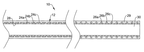
In at least some embodiments, the inventive catheter 10 includes a support
structure or braid 20 that has the desirable features of both a flat wire and
a round
wire as illustrated in Figure 2. For exainple, braid 20 is made up of a
plurality of
individual wires 22 (indicated in Figure 2 by reference numbers 22a, 22b, and
22c)
that are braided together. In at least some embodiments, each of the wires
22a/22b/22c have a first section 24a/b/c having a non-circular cross-sectional
shape
and a second section 26a/b/c having a generally circular cross-sectional shape
along
the individual wires. Other embodiments include only some of the wires 22a/b/c
having a non-circular first section 24a/b/c. According to these embodiments,
braid 20
includes a mixture of some of wires 22a/b/c having first section 24a/b/c and
second
section 26a/b/c whereas some of the other wires 22a/b/c may have a constant
shape
and/or only include differences in diameter.
First sections 24a/b/c and second sections 26a/b/c can be disposed about a
core
member 28 at the appropriate location so as to impart the desired
characteristics to
catheter 10. For example, it may be desirable to dispose first sections
24a/b/c near
proximal portion 14 of catheter shaft 12 so as to provide a desirable level of
proximal
torque response. In addition, it may be desirable to dispose second sections
24a/b/c
near distal portion 16 of catheter shaft 12 so as to provide a desirable level
of distal
curve performance. Of course, the precise positioning of first sections
24a/b/c and
-4-
CA 02586204 2007-05-02
WO 2006/055201 PCT/US2005/038626
second sections 26a/b/c can vary greatly and can include any position along
the length
of catheter shaft 12 for either sections 24a/b/c or 26a/b/c.
It should be noted that although Figure 2 depicts wires 22a/b/c having first
sections 24a/b/c (as well as second sections 26a/b/c) longitudinally aligned,
this need
not be the case. Longitudinally aligned is understood to mean that each of the
first
sections 24a/b/c are located at about the same longitudinal position along
shaft 12 and
each of the second sections 26a/b/c are located at about the same longitudinal
position
along shaft 12. Numerous einbodiments are contemplated that include non-
aligned
first sections 24a/b/c and/or second sections 26a/b/c. For example, first
section 24a of
wire 22a and first section 24b of wire 22b may be longitudinally aligned with
second
section 26c of wire 22c. Moreover, any of wires 22a/b/c may include multiple
first
sections 24a/b/c and/or multiple second sections 26a/b/c that can be dispersed
anywhere along the length of catheter shaft 12 and may or may not be
longitudinally
aligned with analogous sections.
Wires 22a/b/c may be made from any suitable material such as a metal, metal
alloy, polymer, metal-polymer composite, and the like, or any other suitable
material.
Some examples of suitable metals and metal alloys include stainless steel,
such as
304V, 304L, and 316LV stainless steel; mild steel; nickel-titanium alloy such
as
linear-elastic or super-elastic nitinol, nickel-chromium alloy, nickel-
chromium-iron
alloy, cobalt alloy, tungsten or tungsten alloys, MP35-N (having a composition
of
about 35% Ni, 35% Co, 20% Cr, 9.75% Mo, a maximum 1% Fe, a maximum 1% Ti, a
maximum 0.25% C, a maximum 0.15% Mn, and a maximum 0.15% Si), hastelloy,
monel 400, inconel 825, or the like; other Co-Cr alloys; platinum enriched
stainless
steel; or other suitable material.
In some embodiments, wires 22a/b/c may be made from, doped with, or
otherwise include a radiopaque material. Radiopaque materials are understood
to be
materials capable of producing a relatively bright image on a fluoroscopy
screen or
another imaging technique during a medical procedure. This relatively bright
image
aids the user of catheter 10 in determining its location. Some examples of
radiopaque
materials can include, but are not limited to, gold, platinum, molybdenum,
palladium,
tantalum, tungsten or tungsten alloy, plastic material loaded with a
radiopaque filler,
and the like.
Wires 22a/b/c, or other portions of catheter 10, may include a sheath or
coating such as a hydrophobic, hydrophilic, lubricious, protective, or any
other
-5-
CA 02586204 2007-05-02
WO 2006/055201 PCT/US2005/038626
suitable type of coating. For example, shaft 12 may include a sheath 29.
Suitable
lubricious polymers are well known in the art and may include silicone and the
like,
hydrophilic polymers such as high-density polyethylene (HDPE),
polytetrafluoroethylene (PTFE), polyarylene oxides, polyvinylpyrolidones,
polyvinylalcohols, hydroxy alkyl cellulosics, algins, saccharides,
caprolactones, and
the like, and mixtures and coinbinations thereof. Hydrophilic polyiners may be
blended among themselves or with formulated amounts of water insoluble
compounds
(including some polyiners) to yield coatings with suitable lubricity, bonding,
and
solubility. Some other examples of such coatings and materials and methods
used to
create such coatings can be found in U.S. Patent Nos. 6,139,510 and 5,772,609,
the
disclosures of which are incorporated herein by reference.
Figure 3 is a cross-sectional view of catheter 10. Here the non-circular
(e.g.,
flat or ribbon-like) cross-sectional shape of first sections 24a/b/c and the
generally
circular cross-sectional shape for second sections 26a/b/c can be more clearly
seen.
Further details regarding the numerous options for shape of first sections
24a/b/c
and/or section sections 26a/b/c are discussed in more detail below.
Also seen in Figure 3 is that core meinber 28 is a catheter core and it
includes
a lumen 30, for exainple, a guidewire lumen. As such, this figure is intended
to
explicitly demonstrate' that braid 20 can be used in conjunction with
catheters.
However, braid 20 is not intended to be limited to just catheters as any
suitable
medical device may benefit from it design advantages. For example, Figure 4
depicts
medical device 110, which takes the form of a guidewire. Guidewire 110
includes
core meinber or core wire 128 having braid 120 disposed thereon. Braid 120 is
essentially the same in fonn and function as braid 20 so that the description
of the
attributes of braid 20 can be applied to braid 120, to the extent applicable.
In some
embodiments, guidewire 110 may include a polymer jacket 130 and/or a sheath
129.
Figures 5-8 illustrate some of the method steps suitable for making catheter
10
or other similarly configured medical devices. Figure 5 depicts wire 22. Wire
22 is
similar to other wires used to construct a braid for a medical device.
However, wire
22 includes first section 24' (reference number 24' is intended to distinguish
this
unmodified fonn of the first section of wire 22 from first section 24) and
second
section 26. Sections 24'/26, in wire 22 prior to construction, are both
generally round
and can be distinguished by differences between their respective diameters.
For
example, by comparing Figure 6 (depicting the diameter of first section 24')
with
-6-
CA 02586204 2007-05-02
WO 2006/055201 PCT/US2005/038626
Figure 7 (depicting the diameter of second section 26), it can be seen that
second
section has a smaller diameter.
The diameter of sections 24'/26 may vary for a given wire. For example,
some exemplary wires 22 may include first section 24' with a diameter of about
0.002
to about 0.005 inches and second section 26 with a diameter of about 0.001 to
about
0.004 inches. Wires 221ike these are widely available from a number of
commercial
sources or can be manufactured from commercially available sources of wires or
the
appropriate starting material. For example, wire 22 can be manufactured by
narrowing a portion so as to define second section 26 using known drawing,
molding,
machining, or similar techniques.
Figure 8 is a perspective view of the wire 22 where first section 24 is
altered
so as to have a non-circular cross-sectional shape. According to this
embodiment,
first section 24 is flattened so that it has a rectangular or ribbon-like
cross-sectional
shape. By altering a portion of wire 22, first section 24 and second section
26 remain
continuous with one another. This obviates the need to attempt to attach,
weld, or
otherwise bond together two dissimilarly shaped wires. As described above, the
ribbon-like shape may be desirable for a number of reasons including improved
torque response. First section 24, however, is not intended to be limited to
precisely
this shape because numerous alternative shapes are also contemplated including
polygons, ovals, and the like, or any other suitable shape. Figures 10-12
illustrate just
a few examples of alternative shapes. For example, Figure 10 illustrates wire
222
having first section 224 that has a semi-circular cross-sectional shape.
Figure 11
illustrates wire 322 having first section 324 that has a triangular cross-
sectional shape.
Figure 12 illustrates wire 422 having first section 424 that has a hexagonal
cross-
sectional shape. Regardless of which shape first section 24 takes the fonn of,
wires
22a/b/c can be braided about core member 28 as shown in Figure 13. In order to
create the desired shape for first section 24 (or any of the alternatives
thereof), any
suitable alteration technique may be utilized. For example, any suitable
stainping,
molding, machining, or casting technique can be used.
Figure 14 is a partially cut away illustration of another example medical
device 510. Medical device 510 is similar to any of the other devices
disclosed herein
except that in addition to having braid 520 with wires (please note that for
clarity
purposes the individual wires are not labeled in this drawing) each having
first section
524 and second section 526, the wires further include a third section 532.
Third
-7-
CA 02586204 2007-05-02
WO 2006/055201 PCT/US2005/038626
section 532, for example, may have a non-circular cross-sectional area. The
cross-
sectional shape of third section 532 may or may not be the same as first
section 524.
This embodiment demonstrates that the wires making braid 520 need not be
limited to
just a single non-circular or to a single generally round section.
Also shown in Figure 14 is an example of the longitudinal and/or spatial
distribution of sections 524/526/532 that may be configured to provide device
510
with the desired characteristics. For example, second section 526 is disposed
adjacent
a curved region 534 of device 510. Because second section 526 includes wires
having
a generally circular cross-sectional shape, second section 526 can provide a
desired
level of curve support adjacent curved region 534. In addition, having non-
circular
first section 524 and third section 532 (which, incidentally, may also be non-
circular
or generally circular but with, for example, a different diameter than second
section
526) allows braid 520 to provide the desired level of torque response as well
as the
other desirable features of such a configuration.
It should be understood that this disclosure is, in many respects, only
illustrative. Changes may be made in details, particularly in matters of
shape, size,
and arrangement of steps without exceeding the scope of the invention. The
invention's scope is, of course, defined in the language in which the appended
claims
are expressed.
-8-