Note: Descriptions are shown in the official language in which they were submitted.
CA 02586243 2007-09-17
-1-
APPARATUS AND METHOD USING COMPRESSED CODES FOR
SCHEDULING BROADCAST INFORMATION RECORDING
This application is divided from Canadian Patent Application Serial Number
2,117,334 filed December 11, 1992.
1. Field of the Invention
This invention relates generally to video cassette recorder systems and
particularly to the timer preprogramming feature of video cassette recorders
(VCRs)
and to an apparatus and method for using encoded information to shorten the
time
required to perform timer preprogramming and also an apparatus and method for
enabling a user to selectively record, for later viewing, detailed information
that is
associated with an earlier publication or broadcast of an advertisement.
2. Prior Art
The video cassette recorder (VCR) has a number of uses, including playing
back of tapes filmed by a video camera, playing back of pre-recorded tapes,
and
recording and playing back of broadcast and cable television programs.
To record a television program in advance of viewing it, a two-step process is
often used: (1) obtain the correct channel, date, time and length (CDTL)
information
from a television program guide, and (2) program this CDTL information into
the
VCR. Depending on the model, year and type of the VCR, the CDTL information
can
be programmed in various ways including: (i) pushing an appropriate sequence
of
keys in the console according to instructions contained in the user's manual,
(ii)
pushing an appropriate sequence of keys in a remote hand-held control unit
according
to
CA 02586243 2007-05-08
-2-
instructions contained in the user's manual (remote programming), and (iii)
executing
a series of keystrokes in the remote hand-held control unit in response to a
menu
displayed on the television screen (on-screen programming). Other techniques
for
timer preprogramming have been suggested including: (iv) qading in certain bar-
code
information using a light pen pight pen prograinming); and (v) entering
instructions
through a computer or telephone modem. These various methnds differ only in
the
physical means of specifying the information while.xhe contents, being CDTL
and
certain power/clock/timer on-off commands are generally common although the
detailed protocol can vary with different model VCRs. Methods (i) and (ii)
described
above can require up to 100 keystrokes, which has inhibited the free use of
the timer
preprogramming feature of VCRs. To alleviate this, new VCR models have
included
an "On-Screen Programming" feature, which permits remote input of CDTL
information in response to a menu displayed on the television screen.
Generally on
screen programming of CDTL information requires an average of about 18
keystrokes,
which is less than some of the prior methods but still rather substantial.
Some of the
other techniques such as (iv) above, require the use of special equipment such
as a bar
code reader.
In general the present state of the art suffers from a number of drawbacks.
First, the procedure for setting the VCR to record in advance can be quite
complex and
confusing and difficult to learn; in fact, because of this many VCR owners
shun using
the timer preprogramming record feature. Second, the transcription of the CDTL
information to the VCR is hardly ever error-free; in fact, many users of VCR's
timer
preprogramming features express concern over the high incidence of programming
errors. Third, even for experienced users, the process of entering a lengthy
sequence
of information on the channel, date, time and length of desired program can
become
tedious. Fourth, techniques such as reading in bar-code information or using a
computer require special equipment. These drawbacks have created a serious
impedance in the use of a VCR as a recording device for television programs.
The
effect is that time shiftin; of proarams has not become as popular as it once
was
thought it would be. Accordingly, there is a need in the art for a simpler
system for
effecting VCR timer preprogramming which will enable a user to take advantage
of the
recording feature of a VCR more fully and freely.
The prior art in the area of enabling a user to selectively record for later
viewing, detailed information associated with an advertisement is the familiar
advertisement by a network during a television channel commercial break that
there
will be "news at 11 " or that there will be an "interview with the winning
coach at 9".
A viewer watching the channel that sees/hears this announcement could
preprogram his
CA 02586243 2007-05-08
3
VCR to record the "news" or "interview" at the appropriate time. Thus, the
concept
Of having a cue broadcast simultaneously with a advertisement that alerts a
user that
supplemental information regarding the advertisement will be broadcast at a
later time
can be implemented easily with standard apparatus such as a television and a
VCR
and is not new to the state of the art. The user could also be informed of an
"interview with the winning coach" through print advertisement, which would
indicate the channel time and date of the interview. When the user is informed
either
through a broadcast or a printed advertisement that a winning team's coach
will be
interviewed later that day, the viewer uses his standard remote controller to
program
his VCR to automatically record this later program. The VCR stores the
schedule
information from the controller and, via its display panel, provides
acknowledgment
to the user of his programming commands.
US Patent No. 4,977,455 for a System and Process for VCR Scheduling
discloses a television broadcast system in which a cue is broadcast and
displayed
simultaneously with a primary program. The cue alerts a user that supplemental
information regarding the primary program will be broadcast at a later time.
If the
user responds to the cue via a remote controller, then data embedded in the
primary
program broadcast during the video blanking interval segment of the video
signal, but
not visible to the viewer, will be automatically stored and interpreted by a
microprocessor and used to control a VCR to record the supplemental broadcast
at the
later time. Young does not contemplate the use of printed medial at all and
requires
that a special unit be associated with the television receiver to store and
interpret the
data embedded in the primary program broadcast, and also to respond to the
user cue,
for the system to work at all, even for television advertisements, as shown in
elements
4, 5, 9, 10, and 15 of FIG. 1, of 4,977,455.
Summary of the Invention
The present invention provides an improved system for the selection and
entering of channel, date, time and length (CDTL) information required for
timer
preprogramming of a VCR which is substantially simpler, faster and less error-
prone
than present techniques. The invention also provides an improved apparatus and
method for enabling a user to selectively record, for later viewing, detailed
CA 02586243 2007-05-08
-4-
information that is associated with an earlier publication or broadcast of an
advertisement.
In accordance with the invention, to program the timer preprogramming
feature of a video system, there is an apparatus and method for using encoded
video
recorder/player timer preprogramming information. The purpose is to
significantly
reduce the number of keystrokes required to set up the timer preprogramming
feature
on a VCR. In accordance with this invention it is only necessary for the user
to enter
a code with 1 to 7 digits or more into the VCR. This can be done either
remotely or
locally at the VCR. Built into either the remote controller or the VCR is a
decoding
nieans which automatically converts the code into the proper CDTL programming
information and activates the VCR to record a given television program with
the
corresponding channel, date, time and length. Generally multiple codes can be
entered at one time for multiple program selections. The code can be printed
in a
television program guide in advance and selected for use with a VCR or remote
controller with the decoding means.
The invention enables a user to selectively record information designated by a
digital code, which would be associated with an advertisement. The
advertisement
could be print advertisement or a broadcast advertisement on a television or
radio.
The additional information could be broadcast on a television channel early in
the
rriorning, for example, between midnight and six o'clock in the morning, when
the
broadcast rates are low and it is economical to broadcast detailed information
or
acivertisements of many items, especially expensive ones, such as automobiles
and
real estate. In accordance with this invention it is only necessary for the
user to enter
a digital compressed code associated with an advertisement into a unit with a
decoding means which automatically converts the code into CTL (channel, time
and
length). The unit activates a VCR to record information on the television
channel
starting at the right time and recording for the proper length of time. The
information
will be recorded within the next twenty four hours so it is not necessary to
decode any
date. The user can then view this infonnation at his/her leisure.
Accordingly, the present invention provides an apparatus for using
compressed codes for information broadcast recording that comprises: an
interface
that receives compressed codes each having at least one digit and each
representative
CA 02586243 2007-05-08
-4a-
af, and compressed in length from, the combination of channel, time-of-day and
length commands for an information broadcast and each having an indicator
digit
indicating that the compressed code does not include or represent a date
command; a
decoder that decodes a compressed code having at least one digit and an
indicator
digit indicating that the compressed code does not include or represent a date
command into channel, time-of-day and length commands; and a controller
configured to have a recorder start recording according to the time-of-day
command
during the twenty-four hour period following receipt of the compressed code.
In a further aspect, the present invention provides a method for using
compressed codes for information broadcast recording that comprises: receiving
compressed codes, each having at least one digit and each representative of,
and
compressed in length from, the combination of channel, time-of-day and length
commands for an information broadcast and each having an indicator digit
indicating
that the compressed code does not include or represent a date command into
channel,
time-of-day and length commands; and decoding a compressed code having at
least
one digit and an indicator digit indicating that the compressed code does not
include
or represent a date command into channel, time-of-day and length commands; and
turning the recording function of a recorder on according to the time-of-day
command
during the twenty-four hour period following receipt of the compressed code.
Other features of this invention will be more readily appreciated as the same
becomes better understood by reference to the following detailed descriptions
and
considered in connection with the accompanying drawings in which like
reference
symbols designate like parts throughout the figures.
N 4
CA 02586243 2007-05-08
-5-
Bri Description of the Drawings
FIG. , l is a schematic showing apparatus according to this invention with the
code
decoder means embedded in the vic =~ ~,assette recorder;
1FIG:.2 is a schematic of the VC, nliedded processors for command control and
code decoding;
FIO. 3 is a schematic showing a preferred embodiment according to this
invention
with the code decoder means embedded 'in a remote controller;
FIG. 4 is a schematic of the processor embedded in the remote controller;
FIG. 5 is a schematic of a universal remote controller with the code decoder
means
embedded in the universal remote controller;
FIG. 6 is a flow graph of the G-code decoding technique;
FIG. 7 is a flow graph of the G-code encoding technique;
FIG. 8 is an illustration of part of a television calendar according to this
invention;
FIG. 9 is a flowchart for decoding for cable channels;
FIG. 10 is a flowchart for encoding for cable channels;
FIG. 11 is a flow graph of the G-code decoding for cable channels including
conversion from assigned cable channel number to local cable carrier channel
number;
FIG. 12 is a means for decoding including a stack memory;
FIG. 13 is a flowchart for program entry into stack memory;
FIG. 14 is an operation flowchart for sending programs from remote control
to main unit VCR;
FIG. 15 is a perspective view of an apparatus for using compressed codes for
recorder prepregramming according to a preferred embodiment of the invention;
FIG. 16 is a front view of the apparatus of FIG. 15 showing a forward facing
light emitting diode;
FIG. 17 is a perspective view of the apparatus of FIG. 15 placed in a mounting
stand;
FIG. 17A is a front elevational view of the apparatus of FIG. 15 placed in the
mounting stand as shown in FIG. 17;
FIG. 18 is a detail of the LCD display of the apparatus of FIG. 15;
FIG. 19 is a perspective view showing a manner of placing the apparatus of
FIG. 15 relative to a cable box and a VCR; --
FIG. 20 is a perspective view showing a manner of placing the mounting stand
with the apparatus of FIG. 15 mounted thereon near a cable box and VCR;
FIG. 21 is a schematic showing apparatus for using compressed codes for
recorder prepregramming according to a preferred embodiment of the invention;
I ~ d!
CA 02586243 2007-05-08
-6-
1 FIG. 22 is a detailed schematic showing a preferred embodiment of apparatus
implementing the schematic of FIG. 21
FIG. 23 is a flow graph for program entry into the apparatus of FIG. 15;
FIG. 24 is a flow graph for review and program cancellation of programs
entered into the apparatus of FIG. 15;
FIG. 25 is a flow graph for executing recorder prepregramming using
compressed codes according to a preferred embodiment of the invention;
FIG. 26 is a flow graph for encoding program channel, date, time and length
information into decimal compressed cxides;
FIG. 27 is a flow graph for decoding decimal compressed codes into program
channel, date, time and length information;
FIG. 28 is an embodiment of an assigned channel number/local channel number
table;
FIGs. 29a and 29b are examples of a printed advertisement and a television
broadcast advertisement showing the use of a decimal code for information (I
code);
FIG. 30 is a flow graph for entry of an I code into the apparatus of FIG. 15;
FIG. 31 is a flow graph for encoding channel, time and length (CTL) into an
T cude=
FIG. 32 is a flow graph for decoding an I code channel, time and length
(CTL); and
FIG. 33 illustrates the relationship of time spans and validity period codes.
35
1 I Y 6
CA 02586243 2007-05-08
-7-
1 Deicription of the Preferred Embodiments
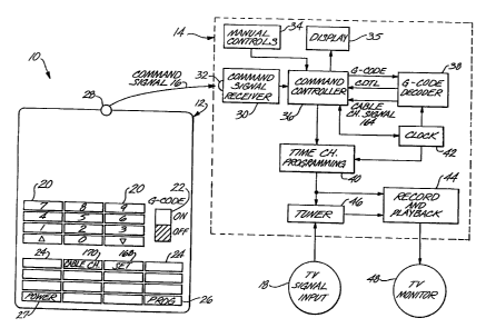
Referring now to the drawings, and more particularly, to FIG. 1, there is
shown
an apparatus for using encoded video recorder/player timer preprogramming
information 10 according to this invention. The primary components include a
remote
controller 12 and a video cassette recorder/player with G-code decoder 14,
which can
be controlled by remote controller 12 via a command signal 16. The remote
controller
12 can have a number of keys, which include numerical keys 20, G-code switch
22,
function keys 24, program key 26 and power key 27. There are means in the
remote
controller 12 that interprets each key as it is pressed and sends the proper
command
signal 16 to the VCR via an infra-red light emitting diode 28. Except for the
G-code
switch 22 on the remote controller 12 in FIG. 1, the remote controller 12 is
essentially
the same as any other remote controller in function. The G-code switch 22 is
provided
just to allow the user to lock the remote controller 12 in the G-code mode
while using
a G-code, which is the name given to the compressed code which is the encoded
CDTL
information, to perform timer preprogramming.
A G-code consists of 1 to 7 digits, although more could be used, and is
associated with a particular program. A user would lookup the G-code in a
program
guide and just enter the G-code on the remote controller 12, instead of the
present state
of the art, which requires that the user enter the actual channel, date, time
and length
(CDTL) commands.
In order to understand the advantages of using a G-code, it is helpful to
describe the best of the current state c+ the art, which is "on screen
programming" with
direct numerial entry. This technique involves about 18 keystrokes and the
user has
to keep switching his view back and forth between the TV screen and the remote
controller while entering the CDTL inforrnation. This situation may be akin to
a user
having to dial an 18 digit telephone number while reading it from a phone
book. The
number of keys involved and the switching back and forth of the eye tend to
induce
errors. A typical keying sequence for timer recording using on-screen CDTL
programming is as follows:
PROG 2 1 15 07 30 2 08 00 2 04 PROG
The first program (PROG) key 26 enters the programming mode. Then a sequence
of
numericals key 20 are pushed. The 2 means it is timer recording rather than
time
setting. The I means the user is now entering the settings for program 1. The
15 is
the date. The 07 is starting hour. The 30 is a starting minute. The 2 means
pm. The
next sequence 08 00 2 is the stopping time. The 04 is channel number. Finally,
the
4 4
CA 02586243 2007-05-08
-8-
1 PROG is hit again to exit the program mode.
By contrast, this command could have been "coded" and entered in a typical
G-code sequence as follows: PROG. 1138 PROG. To distinquish that the command
is a coded G-code, the G-code switch 22 should he turned to the "ON" position.
Instead of having a switch, a separate key "G" can be used. The G-code
programming
keystroke sequence would then be: G 1138 PROG.
The use of a G-code does not preclude "on-screen" confirmation of the
program information that has been entered. When the keystrokes "PROG 1138
PROG"
are entered with the G-code switch in the. "ON" position, the G-code would be
decoded and the television could display the following message:
PROGRAM DATE START TIME STOP TIME CHANNEL
1138 15 7:30 PM 8:00 PM 4
In order for the G-code to be useful it must be decoded add apparatus for that
purpose must be provided. Referring to FIG. 1, a video cassette
recorder/player with
G-code decoder 14 is provided to he used in conjunetion with remote controller
12.
The command signal 16 sent from the remote controller 12 is sensed by the
photodiode
32 and converted to electrical signals by command signal receiver 30. The
electrical
signals are sent to a command controller 36, which interprets the commands and
determines how to respond to the commands. As shown in FIG. 1, it is also
possible
for the command controller 36 to receive commands from the manual controls 34
that
are normally built into a VCR. If the command controller 36 determines that a
G-code
was received then the G-code will be sent to the G-code decoder 38 for
decoding. The
G-code decoder 38 converts the G-code into CDTL information, which is used by
the
command controller 36 to set the time/channel programming 40. Built into the
VCR
is a clock 42. This is normally provided in a VCR and is used to keep track of
the
date and time. The clock 42 is used primarily by the time/channel programming
40
and the G-code decoder 38 functions. The time/channel programming 40 function
is
set up with CDTL information by the command controller 36. When the proper
date
and time is read from clock 42, then the time/channel programming 40 function
turns
the record/playback 44 function "ON" to record. At the same time the tuner 46
is
tuned to the proper channel in the television signal 18. Later the-user can
command
the record/playback 44 function to a playback mode to watch the program via
the
television monitor 48.
An alternate way to control the recorder is to have the command controller 36
keep all the CDTL information instead of sending it to the time/channel
programming
CA 02586243 2007-05-08
-9-
1 40. The cammand controller would also keep track of the time by periodically
reading
clock 42. The command controller would then send commands to the time/channel
programming 40 to turn on and off the recorder and tt - tuner 46 to cause it
to tune to
the right.ehaeiarl at the right time according to the CDTL information.
Ttie clock 42 is also an input to G-code decoder 38, which allows the G-code
decoding to, be a function of the clock, which lends a measure of security to
the
decoding technique and makes it harder to copy. Of course this requires that
the
encoding technique must also b.e a function of the clock.
A possible realization of the command controller 36 and the G-code decoder
38 is shown in FIG. 2. The command controller 36 function can be realized with
a
microprocessor 50, a random access memory 52 and a read only memory 54, which
is used for program storage. The input/output 56 function is adapted to
receive
commands from the command signal receiver 30, the manual controls 34 and the
clock
42, and to output signals to a display 35, the clock 42, and the time/channel
programming 40 function. If the microprocessor 50 interprets that a G-code has
been
received, then the G-code is sent to microcontroller 60 for decoding. The
micraccintroller 60 has an embedded random access memory 62 and an embedded
read
only memory 64 for program and table storage. The clock 42 can be read by both
microprocessor 50 and microcontroller 60.
An alternative to having microcontroller 60 perform the G-code decoding is to
build the G-code decoding directly into the program stored in read only memory
54.
This would eliminate the need for microcontroller 60. Of course, other
hardware to
perform the G-code decoding can also be used. The choice of which
implementation
to use is primarily an economic one.
The blocks in Figs. 1 and 2 are well known in the prior art and are present in
the
following patents: Fields, patent no. 4,481,412; Scholz, patent no. 4,519,003;
and
Brugliera, patent no. 4,631,601. For example, clock 42 is analogous to element
7 in
Scholz and element 17 in Brugliera. Other analogous elements are: command
signal
receiver 30 and Scholz 14 and Brugliera 12; tuner 46 and Scholz 6 and
Brugliera 10;
time/channel programming 40 and Scholz 8, 11 and Brugliera 16; record &
playback
44 and Scholz 1, 2, 4; command=controller 36 and Scholz 11, 10 and Brugliera
12;
microprocemor 50 and Fields 27; RAM 62 and Fields 34; ROM 54 and Fields 33;
manual controls 34 and Scholz 15, 16; and remote controller 12 and Scholz 26
and
Brugliera 18.
FIG. 3 illustrates an alternate preferred embodiment of this invention. In
FIG.
3 a remote controller with embedded G-code decoder 80 is provided. The remote
controller with embedded G-cxide decader 80 is very similar to remote
controller 12,
CA 02586243 2007-05-08
-10-
I except for the addition of the G-code decoder 82. Note that it is also
possible in any
remote controller to provide a display 84. The remote controller with embedded
G-
code decoder 80 would be used in conjunction with a normal video cassette
recorder/player 70, which would not be required to have an embedded G-code
decoder.
The numerals for the subelements of video cassette recorder/player 70 are the
same as
described above for the video cassette recorder/player with G-code decoder 14
and
have the same function, except for the absence of G-code decoder 38. This
preferred
embodiment has the advantage that it can be used in conjunction with VCRs that
are
presently being used. These do not have a G-code decoding capability.
Replacing
their remote controllers with ones that have this capability built-in can
vastly improve
the capability to do timer preprogramming for a modest cost.
FIG. 4 illustrates a possible realization of the G-code decoder-82 huilt into
the
remote controller with embedded G-code decoder 80. A microprocessor 60 can he
used as before to decode the G-code, as well as interface with the display 84,
a clock
85, the keypad 88 and the light emitting diode 28. Alternately, other hardware
implementations can be used to perform the G-code decoding. The clock 85 is
provided in the remote controller 80 so that the G-code decoder 82 can be made
to
have the clock 85 as one of its inputs. This allows the G-code decoding to be
a
function of the clock 85, which lends a measure of security to the decoding
technique
and makes it harder to copy.
The remote controller with embedded G-code decoder as described above
would send channel, date, time and length information to the video cassette
recorder/player 70, which would use the CDTL information for tuning into the
correct
channel and starting and stopping the recording function. The remote
controller may
have to he unique for each different video cassette recorder/player, because
each brand
or model may have different infrared pulses for each type of information sent
such as
the channel number keys and start record and stop record keys. The particular
infrared
pulses used for each key type can be called the vocabulary of the particular
remote
controller. Each model may also have a different protocol or order of keys
that need
to be pushed to accomplish a function such as timer preprogramming. The
protocol
or order of keys to accomplish a func.-tion can be called sentence structure.
If there is
a unique remote controller built for each model type, then the proper
vocabulary and
sentence structure can be built directly into the remote controller._
An alternate to having the remote controller with embedded G-code decoder
send channel, date, time and length information to the video cassette
recorder/player
70, is to have the remote controller with embedded G-code decoder perform more
operations to simplify the interfacing problem with existing video cassette
1 I I Ar0
CA 02586243 2007-05-08
-11-
recorder/players. In particular, if the remote controller not only performs
the G-code
decoding to CDTL, but also keeps track of time via clock 85, then it is
possible for the
remote controller to send just channel, start record and stop commands to the
video
cassette recorder/player. :The.phannel, start and stop are usually basic one
or two key
commands, which means" there is no complicated protocol or sentence structure
involved. Thus, to commun'icate with a diverse set of video cassette
recorder/player
models it is only necessary to have memory within the remote controller, such
as ROM '
64 of FIG..4, for storing the protocol for all the models or at least a large
subset. The
G-code would be entered on the remote controller as hefore and decoded into
channel,
date, time and length information, which would he stored in the remote
controller. Via
clock 85, the time would be checked and when the correct time arrives the
remote
controller would automatically send out commands to the VCR unit'for tuning to
the
correct channel and for starting and stonping the recording. It is estimated
that only
two (2) bytes per key for about 15 keys need to be stored for the vocabulary
for each
video cassette recorder/player model. Thus, to cover 50 models would only
require
about 30*50 = 1500 bytes of memory in the remote controller. It would be
necessary
to position the remote controller properly with respect to the VCR unit so
that the
infrared signals sent by the remote controller are received by the unit.
Another preferred embodiment is to provide a universal remote controller 90
with an embedded G-code decoder. Universal remote controllers provide the
capability
to mimic a number of different remote controllers. This reduces the number of
remote
controllers that a user needs to have. This is accomplished by having a learn
function key 94 function on the universal remote controller, as shown in FIG.
5. If the learn
function key 94 is pushed in conjunction with another key, the unit will enter
into the
learn mode. Incoming infra-red (IR) pulses from the remote controller to be
learned
are detected by the infra-red photodiode 96, filtered and wave-shaped into
recognizable
bit patterns before being recorded by a microcontroller into a battery-backed
static
RAM as the particular IR pulse pattern for that particular key. This is done
for all the
individual keys.
An example of more complex learning is the following. If the learn function
key.94 in conjunction with the program key 26 are pushed when the G-code
switch is
"ON", the -unit will recognize that it is about to record the keying sequence
of a
predetermined specific example of timer preprogramming of- the particular VCR
involved. The user will then enter the keying sequence from which the
universal
remote controller 90 can then deduce and record the protocol of the timer
preprogramming sequence. This is necessary because different VCRs 'naay have
different timer preprogramming command formats.
1 s u,CA 02586243 2007-05-08
-12-
1 If keys are pushed without the learn function key 94 involved, the
microcontroller should recognize it is now in the execute mode. If the key is
one of
the direct command keys, the microcontroller will read back from its static
RAM the
stored pulse sequence and send out command words'through the output parallel
I/O to
pulse the output light emitting diode 28. If the key is the PROG key and the G-
code
switch is "OFF", then the microcontroller should recognize the following keys
up to
the next PROG key as a timer preprogramming CDTL command and send it out
through the light emitting diode 28. If the G-wde switch 22 is set to "ON" and
the
program key 26 is pushed, the microcontroller should recognize the following
keys up
to the next PROG key as a G-code command for timer preprogramming. It will
decode the G-code into channel, date, start time and length (CDTL) and the
microcontroller will then look up in it's static RAM "dictionary" the
associated
infra-red pulse patterns and concatenate them together before sending them off
through
the output parallel I/O to pulse the light emitting diode 28 to send the whole
message
in one continuous stream to the VCR.
FIG. 4 illustrates a possible realization of the G-code decoder 92 that could
be
built into the universal remote controller with embedded G-code decoder 90. A
microcontroller 60 can be used as before to decode the G-code, as well as for
interfacing with the input/output functions including the photodiode 96.
Alternately,
the G-code decoding can be performed with other hardware implementations.
The universal remote controller can also be used in another manner to simplify
the interfacing problem with existing video cassette recorder/players. In
particular, if
the universal remote controller performs not only the G-code decoding to CDTL,
but
also keeps track of time via clock 85 in FIG. 4, then it is possible for the
universal
remote controller to send just channel, start record and stop commands to the
video
cassette recorder/player, which as explained before, are usually basic one key
commands, which means there is no complicated protocol or sentence structure
involved. Thus, to communicate with a diverse set of video cassette
recorder/player
models it is only necessary for the universal remote controller to "learn"
each key of
the remote controller it is replacing. The G-code would be entered on the
universal
remote controller. a.c before and.- decoded into channel, date, time and
length
information, which would be stored in the universal remote controller. Via
clock 85,
the time would be checked and when the correct time arrives the universal
remote
controller would automatically send out commands to the VCR unit for tuning to
the
correct channel and for starting and stopping the recording. It would be
necessary to
position the universal remote contrbller properly with respect to the VCR unit
so that
the signals sent by the universal remote are received by the VCR unit.
o F
CA 02586243 2007-05-08
=13-
There are a number of ways that the Ci-c:ode decoding can be performed. The
most obvious way is to just have a l,arge look up table. The G-code would be
the
index. Unfortunately, this would he va:ry inefficient and result in a very
expensive
decoder due to the memory involved. The tcital storage involved is a function
of the,
number of total combinations. If we allow for 128 channels, 31 days in a
month, 48
on the hour and on the half hour start,times in a-'twenty four hour day, and
16 length
selections in half hour increments,. then the total number of combinations is
128x31 x48x 16 = 3,047,424. This number of combinations can he represented by
a
7 digit number. The address to the table would he the 7 digit number. In the
worse
case, this requires a lookup table that has ahout 4,000,000 rows by 15 to 16
digital
columns, depending on the particular protocol. These digital columns would
correspond to the CDTL information required for "on screen programming". Each
digit could be represented by a 4 hit binary number. Thus, the total storage
number
of bits required for the lookup table would he about 4,000,000x 16x4 =
256,000,000.
The present state of the art has about 1 million bits per chip. Thus, G-code
decoding
using a straightforward table lookup would require a prohibitively expensive
number
of chips.
Fortunately, there are much more clever ways of performing the G-code
elecocling. FIG. 6 is a tlow diagram of a preferred G-code decoding technique.
To
understand G-code decoding, it is easiest to first explain the G-code encoding
technique. for which FIG. 7 is the flow chart. Then the G-code decoding
technique,
which is the reverse of the G-code encoding will he explained.
The encoding of the G-codes can be done on any computer and is done prior
to preparation of any program guide that would include G-codes. For each
program
that will bc; printed in the guide, a channel, date, time and length (CDTL)
code 144 is
entered in r:tep 142. Step 146 separately reads the priority for the channel,
date, time
and length in the priority vector storage 122, which can be stored in read
only memory
64. The priority vector storage 122 contains four tables: a priority vector C
table 124,
a priority vector D table 126, a priority vector T table 128 and a priority
vector L table
130.
The channel priority table is ordered so that the most frequently used
channels
have a low priority number. An example of the data that is in priority vector
C table
124 follows.
channel 4 7 2 3 5 6 11 13 ...
priority 0 1 2 3 4 5 6 7...
u
CA 02586243 2007-05-08
-14-
I Generally the dates of a month all have an equal priority, so the low number
days in a month and the low number priorities would correspond in the priority
vector
D table as in the following oxample.
date 1 2 3 4 5 6 7 8 9 10 ...
priority 0 1 2 3 4 5 6 7 8 9 ...
The priority of the start times would be arranged so that prime time would
have a low priority number and programs in the dead of the night would have a
high
priority number. For example, the priority vector T table would contain:
time 6:30pm 7:00pm 8:00pm 7:30pm ...
priority 0 1 2 3 ...
An example of the data - that is in the priority vector L table 130 is the
following:
length of program (hours) 0.5 1.0 2.0 1.5 3.0 ...
priority 0 1 2 3 4 ...
Suppose the channel date time length (CDTL) 144 data is 5 10 19.00 1.5,
which means channel 5, 10th day of the month, 7:00 PM, and 1.5 hours in
length, then
for the above example the C,,DP,TP,Lp data 148, which are the result of
looking up the'
priorities for channel, date, time and length in priority tables 124, 126, 128
and 130
of FIG. 7, would be 4 9 1 3. Step 150 converts CPDP,TP,Lp data to binary
numbers.
The number of binary bits in each - conversion is determined by the number of
combinations involved. Seven bits for CP, which can he denoted as C, C6 C5 C4
C3
C2 C,, would provide for 128 channels. Five bits for D., which can be denoted
as DS
D, D, D, D,, would provide for 31 days in a month. Six bits for T., which can
be
denoted as T6 TS T4 T, T: T,, would provide for 48 start times on each half
hour of a
twenty four. hour day. Four.bits for length, which can be denoted as L, L, L,
L,,
would provide for a program length of up to 8 hours in half hour steps.
Together there
are 7+5+6+4 = 22 bits of information, which correspond to 2**22 = 4,194,304
combinations.
The next step is to use bit hierarchy key 120, which can be stored in read
only
memory 64 to reorder the 22 bits. The bit hierarchy key 120 can be any
ordering of
the 22 bits. For example, the bit hierarchy key might be:
a u,
CA 02586243 2007-05-08
-15-
LK C: ... T. C.. T, C, L, D., D. D, D, D,
2221...1098765432 1
Ideally the bit hierarchy key is ordered so that programs ntost likely tg be
the
subject of timer preprogramming would have a low value binary number, which
would
eliminate keystrokes for timer preprogramming the most popular programs.
Sitice all
the date information has equal priority, then the D, Ds D, D, D, hits are
first. Next
T, C, L, are used, because for whatever date it is necessary to have a time
channel and
length and T, C, L, are the most probable in each case due to the ordering of
the
~
priority vectors in priority vector storage 122. The next hit in the hierarchy
key is
determined by the differential probabilities of the various combinations. One
must
know the probabilities of all the channels, times and lengths for this
calculation to be
performed.
For example, the probability for channels may he:
channel 4 7 2 3 5 6 11 13 ...
priority 0 1 2 3 4 5 6 7...
probability(%) 5 4.3 4 3 2.9 2.1 2 1.8...
The probabilities for times might he:
time 6:30pm 7:00pm 8:00pm 7:30pm ...
priority 0 1 2 3 ...
probability(%) 8 7.8 6 5 ...
And, the probabilities for lengths might be:
length of program (hours) 0.5 1.0 2.0 1.5 3.0 ...
priority 0 1 2 3 4 ...
probability(%) 50 20 15 5 4
The probabilities associated with each channel, time anJ length, as
illustrated
above, are used to determine the proper ordering. Since the priority vector
tables are
already ordered by the most popular channel, time, and length, the order in
which to
select between the various binary bits for one table, for example selecting
between the
1 L 4
CA 02586243 2007-05-08
-16-
C7 Ch C, C4 C, C, C, bits, is already known. The C, bit would be selected
first
because as the lowest order binary hit it would select between the first two
entries in
the channel priority table. Then the C. bit would he selected and so on.
Similarly, the
T, and L, bits would be used before any of the other time and length bits:, ,A
combination of the C,, T,, L, and D., D, D, D, D, hits should be used first,
sa that
all the information is available for a channel, date, time and length. The DS
D4 IJa D,
D, bits are all used because the date hits all have equal priority and atl are
needed to
specify a date even if some of the bits are binary zero.
At this point the bit hierarchy key could be:
T,C,L,DSD,D,D,D,
The first channel binary hit C, by itself can only select between 2' = 2
c:hannels, and
the first two channels have a probability percent of 5 and 4.3, respectively.
So the
differential probability of C, is 9.3. Similarly, the differential probability
of T, is 8
+ 7.8 = 15.8, and the differential probability of L, is 50 + 20 = 70. If the
rules for
ordering the bit hierarchy key are strictly followed, then the first 8 bits of
the bit
hierarchy key should be ordered as:
C,T,L, DSD,D,D,D,,
because L, has the highest differential priority so it should he next most
significant bit
after D,, followed by T, as the next most signiticant hit, and then C, as the
next most
significant hit. Notice that the bit hierarchy key starts with the least
signiticant bit D,,
and then is tilled in with the highest differential probability bits. This is
for the
purpose of constructing the most compact codes for popular programs.
The question at this point in the encoding process is what should the next
most
significant bit in the hierarchy key be: T,, C,, or L,. This is again
determined by the
differential probabilities, which can be calculated from the above tables for
each bit.
Since we are dealing with binary bits, the C, in combination with C, selects
between
2' = 4 channels or 2 more channels over C, alone. The differential probability
for C.
is then the additional probabilities of these two additional channels and for
the example
this is: 4 + 3 = 7. In a similar manner C, in combination with C, and C.
selects
between 2' = 8 channels or 4 = 2"' more channels over the combination of C,
and
C,. So the differential probability of C, is the additional probabilities of
these four
additional channels,actd for the example this is: 2.9 + 2.1 + 2 + 1.8 = 8.8.
In a
similar manner, the differential probabilities of T, and L, can be calculated
to be 6+
1
CA 02586243 2007-05-08
-17-
11 and 15 + 5 = 20, respectively. Once all the differential probabilities are
calculated, the next step is determining which combinations of bits are more
probable.
Now for the above example, which combination is more probable: T, with C,
Lõ or C_ with T, L,, or L, with T, C,. This wi'll determine the next bit in
the key.
5 So, which is greater: 11x9.3x70= 7161; 7z]5.8x70= 7742; or 20x15.8x9.3=
2938.8?
In this case the combination with the greatest probah#i:ty is 7x15.8x70= 7742,
which
corresponds to C. with T, L,. So, C. is'selected as the next bit in the hit
hierarchy
key.
The next bit is selected in the same way. Which combination is more
probable: C, with T, L,, or T. with C, or C. and L,, or L, with C, or C. and
T,.
For the example shown, which has the greatest probability: 8.8x15.8x70=
9732.8;
11x(9.3+7)x70= 12551; or 20x(9.3+7)x15.8= 5150.8? In this case the-combination
with the greatest probability is 11x(9.3+7)x70= 12551, which corresponds T.
with C,
or C, and L,. So, T, is selected as the next bit in the bit hierarchy key.
This
procedure is repeated for all the differential probabilities until the entire
key is found.
Alternately, the bit hierarchy key can be just some arbitrary sequence of the
bits. It is also possible to make the priority vectors interdependent, such as
making the
length priority vector dependent on different groups of channels. Another
technique
is to make the bit hierarchy key 120 and the priority vector tables 122, a
function of
clock 42, as shown in FIG. 7. This makes it very difficult for the key and
therefore
the coding technique to he duplicated or copied.
For example it is possible to scramble the date bits in the bit hierarchy key
120
as a function of the clock. Changing the order of the bits as a function of
the clock
would not change the effectiveness of the hit hierarchy key in reducing the
number of
binary bits for the most popular programs, because the date bits all are of
equal
priority. This could be as simple as switching the D, and D5 bits
periodically, such as
every day or week. Thus the bit hierarchy key 120 would switch between
... C, T, L, D, D, D, D, D, and
C,T,L,D,DyD,D,Ds.
Clearly other permutations of the bit hierarchy key as a function of the clock
are
possible.
The priority vector tables cbuld also be scrambled as a function of the clock.
For example, the first two channels in the priority channel table could just
be swapped
~ti
CA 02586243 2007-05-08
-18-
periodically. If this technique is followed, then the C. of 148 in FIG. 7
would change
as a function of the clock 42. For example,
channel 4 7 2.: . 3 5 6 11 13...
priority .0 t 2 . 3 4 5 6 7...
would change periodically to:
channel 7 4 2 3 5 6 11 13 ...
priority 0 1 2 3 4 5 6 7...
This would be a fairly subtle security tachnique, because a ilecoder that was
otherwise correct would only fail if those first two channels were being used.
Other
clock dependencies are also possible to provide security for the coding
technique.
However it is derived, the bit hierarchy key 120 is determined and stored. In
step 154 the binary bits of CP,DP,TP,L, are rearranged according to the bit
hierarchy
key 120 to create one 22 bit binary number. Then the resulting 22 bit binary
number
is converted to decimal in the convert binary number to decimal G-code step
156. The
result is G-code 158.
If the priority vector and the bit hierarchy key are well matched to the
viewing
habits of the general population, then it is expected that the more popular
programs
would require no more than 3 or 4 digits for the G-code.
Now that the encoding technique has been explained the decoding technique is
just reversing the coding technique. This is done according to the flow chart
of FIG.
6. This is the preferred G-code decoding that can be built into G-code decoder
38 in
VCR 14 or the remote controller G-code decoders 82 and 92 in FIGs. 3 and 5.
The first step 102 is to enter G-code 104. Next the G-code 104 is converted
to a 22 bit binary number in step 106. Then the bits are reordered in step 108
according to the bit hierarchy key 120 to obtain the reordered bits 110. Then
the bits
are gruupcxl together and converted tu decimal furm in step 112. As this point
we
obtain C,-,DP,T,,,LP data 114, which are the indices to the priority vector
tables. For
the above example, we would have at this step the vector 4 9 1 3. This
CP,DP,TP,Lp
data 114 is then used in step 116 to lookup channel, date, time,.and length in
priority
vector storage 122. The CDTL 118 for the example above is 5 10 19.00 1.5,
which
means channel 5, 10th day of the month, 7:00 PM, and 1.5 hours in length.
If the coding technique is a function of the clock then it is also necessary
to
make the decoding technique a function of the clock. It is possible to make
the bit
I A 4
CA 02586243 2007-05-08
-19-
hierarchy key 120 and the priority vector tables 122, a function of clock 42,
as shown
in FIG. 6. This again makes it very difticult for the key and therefore the
coding
technique to be. duplicated or copied. It is also possible to have the
decoding and
encoding -techniques dependent on any other predetermined or. prepr.ogrammable
algorithm.
Although the a66ve G-code encoding and decoding technique is a preferred
embodiment,. it should be understood that there are many ways to perform the
intent
of the invention which is to reduce the number of keystrokes required for
timer
preprogramming. To accomplish this goal there are many ways to perform the G-
code
encoding and decoding. There are also many ways to make the encoding and
decoding
technique more secure besides just making the encoding and decoding a function
of the
clock. This security can he the restilt of any predetermined or- preprogrammed
algorithm.
It is possible in the G-code coding and decoding techniques to use mixed radix
number systems instead of binary numbers. For example, suppose that there are
only
35 channels, which would require 6 binary hits to be represented;. however, 6
binary
bits can represent 64 channels, because 2 = 64. The result is that in a
binary number
system there are 29 unnecessary positions. This can have the effect of
possibly making
a particular G-code longer than it really needs to be. A mixed radix number
system
can avoid this result. For example, for the case of 35 channels, a mixed radix
number
system with the factors of 7' and 5 can represent 35 combinations without any
empty
space in the code. The allowed numbers for the 7' factor are 0, 1, 2, 3-, and
4. The
allowed numbers for the 5 factor are 0. 1, 2, 3, 4. 5, and 6. For example,
digital 0
is represented in the mixed radix number system as 00. The digital number 34
is
represented in the mixed radix number system as 46, because 4*71+6*50 = 34.
The
major advantage of a mixed radix number system is in prioritizing the
hierarchy key.
If the first 5 channels have about equal priority and the next 30 are also
about equal,
then the mixed radix number system allows the two tiers to be accurately
represented.
This is not to say that a mixed radix number system is necessarily preferable.
Binary
numbers are easier to represent in a computer and use of a fixed radix number
system
such as binary numbers allows a pyramid of prioritization to be easily
represented in
the hierarchy key.
Another feature that is desirable in all of the embodiments is the capability
to
key in the G-code once for a program and then have the resulting CDTL
information
used daily or weekly. Ordinarily the CDTL information is discarded once it is
used.
In the case of daily or weekly recording of the same program, the CDTL
information
k A
CA 02586243 2007-05-08
-20-
is stored_and used until it is cancelled. The desire to repeat the program
daily or
weekly can be performed by having a "WEEKLY" or "DAILY" button on the remote
-controller or built into the VCR manual controls. Another way is to use one
key, such
as the PROG, key aind push it multiple times within= a certain period of timd,
such as
twice to''specify daily'or thrice to specify weekly. For example, if the G-
code switch
is "ON" aiid the G-codewI for the desired program is 99 then daily recording
of the
program can be'selected by the following keystrokes:
"PROG 99 DAILY PROG"
or by:
"PROG 99 PROG PROG".
The G-code 99 would be converted to CDTL information, which would be stored
and
used daily in this case. The recording would begin on the date specified and
continue
daily after that using the same channel time and length information. A slight
twist is
that daily recording could be automatically suspended during the weekends,
because
most daily programs are different on Saturday and Sunday.
Once a daily or weekly program is set up, then it can be used indefinitely.
If it is desired to cancel a program and if there is a"CANCEL" button on the
remote
controller or manual control for the VCR, then one way to cancel a program
(whether
it is a normal CDTL, daily or weekly entry) is to key in the following:
"PROG xx CANCEL", where xx is the G-code.
Again as before there are alternate ways of accomplishing this.
If "on screen programming" is available, then the programs that have been
selected for timer preprogramming could be reviewed on the screen. The daily
and
weekly programs would have an indication of their type. Also the G-codes could
be
displayed along with the corresponding CDTL information. This would make it
quite
easy to review the current "menu" and either add more programs or cancel
programs
as desired.
A television calendar 200 according to this invention is illustrated in FIG.
8.
As shown, the television calendar has multiple day of year sections 202,
multiple day
sections 204, multiple time of day sections 206, channel identifiers 208, and
descriptive
program identifiers 210, including the name of the program, arranged in a
manner that
is common in television guide publications. Arranged in relation to each
channel
identifier is a compressed code indication 212 or G-code containing the
channel, date,
time and length information for that entry in the teievisian calendar. FIG. 8
shows
how easy it is to perform timer programming. All one needs to do is find the
program
one wants to watch and enter the compressed code shown in the compressed code
indication. This is in contrast to having to deal with all the channel, date,
time and
. w u
CA 02586243 2007-05-08
-21-
I length entries separately. At least the channel, date and time are
explicitly stated in the
television guide. The length is usually only available by searching the guide
to find
the time of day section 204 where a new program begins and then performing
some
arithmetic to find the length of the program. Using the ciompressed G-code
avoids all
these complications.
For cable television programs, there is an additional issue that needs to be
addressed for the compressed G-code to be useful. In a normal television
guide,
CDTL information is available for all the normal broadcast channels in the
form of
numbers including the channel numbers, such as channel 4 or 7. However, for
cable
channels like HBO, ESPN etc., only the names of the channels are provided in
most
television listings. The reason for this is that in some metropolitan areas,
such as Los
Angeles, there may be only one (1) edition of television guide, but there may
he quite
a few cable carriers, each of which may assign HBO or ESPN to different cable
channel numbers. In order for a c:ompressed code such as the G-code to be
applicable
to the cable channels as published by a wide area television guide
publication, the
following approach can be used.
First, all the cable channels would be permanently assigned a unique number,
which would be valid across the nation. For example, we could assign ESPN to
cable
channel 1, HBO as cable channel 2, SHO as cable channel 3, etc. This
assignment
would he published by the television guide publications.
The video cassette recorder apparatus, such as the remote controller, the VCR
unit or both, could then he provided with two (2) extra modes: "set" and
"cable
channel". One way of providing the user interface to these modes would be to
provide
two (2) extra buttons: one called SET and one called CABLE CHANNEL. The
buttons could he located on the video cassette recorder unit itself or located
on a
remote controller, as shown in FIGs 1, 3 and 5, where SET is element 168 and
CABLE CHANNEL is element 170. Of course, other user interfaces are possible.
Next, the television viewer would have to go through a one-time "setting"
procedure of his VCR for all the cable channels that he would likely watch.
This
"setting" procedure would relate each of the assigned numbers for each cable
channel
to the channel number of the local cable carrier. For example, suppose that
the local
cable carrier uses = channel 6 for ESPN, then cable channel number I could be
assigned
to ESPN, as shown in the following table.
1 I I = 4
CA 02586243 2007-05-08
-22-
Cable Channel Assign-ed Channel Number in
Name Cable Chan. Nn. the local cable carrie~
EPSN 1- 6
HBO 2 24
SHO 3 23
DIS 8 25
The user could perform the "setting" procedure by pushing the buttons on his
remote
controller as follows:
SET 06 CABLE CHANNEL I PROGRAM
SET 24 CABLE CHANNEL 2 PROGRAM
SET 23 CABLE CHANNEL 3 PROGRAM
SET 25 CABLE CHANNEL 8 PROGRAM
The "setting" procedure would create a cable channel address table 162, which
would be loaded into RAM 52 of command controller 36. For the above example,
the
cable channel address table 162 would have the following information.
CABLE CHANNEL ADDRESS TABLE 162
1 6
2 24
3 23
8 25
After the "setting" procedure is performed, the TV viewer can now select cable
channels for viewing by the old way: eg. pushing the key pad buttons 24 will
select
N w
CA 02586243 2007-05-08
-23-
1 HBO. He can also do it the new way: eg. by pushing CABLE CHANNEL 2, which
will also select HBO. The advantage of the new way is that the television
guide will
publish [C2] next to the program description, so the viewer will just look up
the
assigned channel number identifier instead of having to remember that HBO is
local
cable channel 24. When the CABLE CHANNEL button is pushed, command
controller 36 knows that it will look up the local cable channel number in
cable channel
address table 162 to tune the VCR to the correct channel.
For timer preprogramming and for using the compressed G-code, a way to
differentiate between broadcast and cable channels is to add an eighth channel
bit,
which would be set to 0 for normal broadcast channels and 1 for cable channels
such
as HBO. This eighth channel bit could be one of the low order bits such as the
third
bit C, out of the eight channel bits, so that the number of bits to- specify
popular
channels is minimized, whether they be normal broadcast or cable channels. For
a
normal broadcast channel, the 7 other bits can he decoded according to
priority vector
C table 124. For a cable channel, the 7 other bits can be decoded according to
a
separate cable channel priority vector table 160, which could be stored in ROM
54 of
microcontroller 36. The cable channel priority vector table can be set ahead
of time
for the entire country or at least for an area covered by a particular wide
area television
guide publication.
A television guide that carries the compressed code known as the G-code will
now print the cable channel information as follows:
6:30 pm
[C2J HBO xxxxxxxxxxxxxxxxxxxxxxxxxxxxxxxx(4679)
xxxxxx(program description)xxxxxxxxxx
xxxxxxxxxxxxxxxxxxxxxxxxxxxxxxxxxxxxx
The [C2] in front of HBO reminds the viewer that he needs only to push CABLE
CHANNEL 2 to select HBO. The (4679) is the G-code indication for this
particular
program.
FIG. 8 shows a.section of a television guide. The cable channels all have an
assigned cable channel number 188 after the cable channel mnemonic. Other than
that
the cable channel information is arranged the same as the broadcast channels
with a
compressed G-code 212 associated with the channel.
For timer preprogramming, the viewer need only enter the number 4679
according to the unit's G-code entry procedure, eg. PROG 4679 PROG. The G-code
decoder unit will decode this G-wde into "cable channel 2" and will also
signal the
oõv
CA 02586243 2007-05-08
-24-
command controller 36 with a cable channel signal 164, as shown in FIGs. 1 and
2,
because the extra channel bit will be "1" which distinquishes that the G-code
is for a
cable channel; then, since the association of "c4ble, channel 2" with channel
24 has
been established earlier in the "setting" procedure,..the command controller,
if it has
received a cable channel signal, will immediately look' up 2 in the cable
channel
address table 162 to translate it to cable channel 24, which will be used as
the
recording channel at the appropriate time. By associating the G-code with the
assigned
cable channel number rather than the.local cable channel number, the G-code
for that
program will be valid in the whole local area, which may have many different
cable
carriers each of which may have different local cable channel numbers.
To include the cable channel compressed G-code feature, the decoding and
encoding algorithms are as shown in FIGs 9 and 10, respectively.- Th.e
encoding
should he explained first before the decoding. The primary change in FIG. 10
from
FIG. 7 is that a cable channel priority vector table 160 has been added and is
used in
look up priority step 180 if a cable channel is being encoded. Also if a cable
channel
is being encoded then the cable channel hit is added in the correct bit
position in the
convert CPDTL.p to binary numbers step 182. This could be bit C,, as discussed
before. The bit hierarchy key could be determined as before to compress the
number
of bits in the most popular programs; however, it needs to be 23 bits long to
accommodate the cable channel bit. The maximum compressed G-code length could
still he 7 digits, because 2=-'= 8,388,608.
The decoding is shown in FIG. 9 and is just the reverse of the encoding
process. After step 108, test cable channel bit 174 is added and effectively
tests the
cable channel bit to determine if it is a"I ". If so then the command
controller 36 is
signaled via cable channel signal 164 of FIGs. I and 2 that the CDTL 118 that
will be
sent to it from G-code decoder 38 is for a cable channel. Then the command
controller
knows to look up the local cable carrier channel number based on the assigned
cable
channel number. In step 176 of FIG. 9, the priority vector tables including
the cable
channel priority vector table 160 are used to look up the CDTL 118
information.
An alternate to having the command controller receive a cable channel signal
164 is for the G-code decoder to perform all of the decoding including the
conversion
from assigned cable channel number to local cable carrier number. This would
be the
case for the remote controller implementation of FIG. 3. FIG. 11 shows the
implementation of the entire decode algorithm if this step is included. All
that needs
to he added is convert assigned channel to local cable carrier channel step
166, which
performs a lookup in cable channel address table 162, if the cable channel bit
indicates
that a cable channel is involved. Step 166 effectively replaces step 174 in
FIG. 9.
CA 02586243 2007-05-08
-25-
1 Another issue that needs addressing is the number of programs that can be
preprogrammed. Since the G-code greatly simplities the process of entering
programs,
it is likely that the user will quickly learn and want to enter a large number
-of
programs; however, some existing VCRs can only store up to four (4) programs,
while
some can store as many as eight. Thus, the user may get easily frustrated by
the
programming limitations of the VCR.
One approach to this problem, is tu perform the compressed G-code decoding
in the remote controller and provide enough memory there to store a large
number of
programs, eg. 20 or 40. The remote controller would have the capability of
transferring periodically several of these stored programs at a time to the
VCR main
unit. To provide this capability, extra memory called stack memory 76 is
required
inside the remote unit, as shown in FIG. 12, which other than that is-
identical to FIG.
4. Stack memory 76 can be implemented with a random access memory, which may
in fact reside in the microcontroller itself, such as RAM 62.
The stack memory 76 is where new entry, insertion & deletion of timer
preprogramming information is carried out. It is also where editing takes
place. The
top memory locations of the stack, for example the first 4 locations,
correspond exactly
to the available timer preprogramming memory in the VCR main unit. Whenever
the
top of the stack memory is changed, the new information will be sent over to
the VCR
main unit to update it.
FIG. 13 shows the sequence of events when the user enters a G-code program
on the keypad of the remote controller. For illustration purposes, suppose the
VCR
main unit can only handle four (4) programs. Suppose also that the stack
memory
capacity is 20 timer preprograms. Referring to the flow chart in FIG.13, when
the
user enters a G-code in step 230, the microcontroller 60 first decodes it into
the CDTL
information in step 234 and displays it on the display unit with the
additional word
"entered" also displayed. The microcontroller then enters the decoded program
into
the stack memory in step 236.
If this is the first program entered, it is placed at the top location of the
stack
memory. If there are already programs in the stack memory, the newly entered
program will first be provisionally placed at the bottom of the stack memory..
The
stack memory will then be sorted into the correct temporal order in step 240,
so that
the earliest program in time will appear in the top location and the last
program in time
will be at the bottom. Notice that the nature of the temporally sorted stack
memory
is such that if stack memory location n is altered, then all the locations
below it will
be altered.
For example, suppose the stack memory has six (6) entries already temporally
I p 4
CA 02586243 2007-05-08
-26-
ordered, and a new entry is entered whose temporal ordering places it in
location 3 (1
being the top location). If this entry is placed into location 3, information
which was
in location 3, 4, 5, 6 will be shifted to locations 4, 5, 6, and 7. L,ocations
1 and 2 will
remain unchanged.
The microcontroller 60, after doing the temporal ordering, checks in step 242
whether the first n entries have changed from before, where for the current
example
n equals 4. In this case, since a new program has been entered into location
3, what
used to. be in location 3 now moves to location 4. Since the VCR's main unit
program
menu of 4 entries should correspond exactly to location I through 4 of the
stack
memory, entries 3 and 4 on the VCR main unit must now be revised. The
microcontroller therefore sends out the new entries 3 & 4 to the main unit, in
step 244
of FIG. 13. If the newly entered program, after temporal ordering, gets
entered into
location 5, then entries I through 4 have not changed from before and the
microcontroller will not send any message to the VCR main unit and the
microcontroller will just resume monitoring the clock 85 and the keyboard 88
as per
step 246. It is assumed that when the user enters the G-code in step 230, the
remote
controller is pointed at the VCR main unit. The other steps of FIG. 13 happen
so fast
that the changes are sent in step 244 while the remote controller is still
being pointed
at the VCR main unit.
If the user decides to delete a program in step 232, the deletion is first
carried
out in the stack memory. If the first 4 entries are affected, the
microcontroller will
send the revised information over to the VCR main unit. If the first 4 entries
are not
affected, then again the remote controller unit will not send anything. The
deletion
will only change the lower part of the stack (lower meaning location 5 to 20).
This
new information will be sent over to the VCR main unit at the appropriate
time.
In the meantime, the VCR main unit will be carrying out its timer
programming function, completing its timing preprogramming entries one by one.
By
the time all 4 recording entries have been completed, the stack in the remote
must send
some new entries over to "replenish" the VCR main unit (if the stack has more
than
4 entries).
The real time clkk 85 in the remote controller unit is monitored by the
microcontroller to determine when the programs in the main unit have been used
up.
Referring to the flow chart in FIG. 14, the microcontroller peFiodically
checks the
clock and the times for the programs at the top of the stack in step 250 (say
the first
4 entries), which are identical to the VCR's main unit's menu. If on one of
the
periodic checks, it is determined that the recording of the main unit's' menu
is
complete, then if there are more entries in the stack, which is tested in step
252, the
CA 02586243 2007-05-08
-27-
1 display unit will be set to a blinking mode or display a blinking message in
step 258
to alert the user to send more programs. Next time the user picks up the
remote unit,
the blinking will remind him that the VCR main unit's program menu has been
completed and it is time to replenish thi! VCR main unit with program entries
stored
in the remote. The user simply picks up the remote and points it towards the
VCR
main unit and presses "ENTER". This will "pop" the top of the stack memory in
step
260, ie. pop all the entries in the stack up by four locations. The
microcontroller will
then send the new "top of the stack" (ie. top 4 entries) over to the VCR main
unit in
step 262. This process will repeat until the whole stack has been emptied.
Another preferred embodiment of an apparatus for using compressed codes for
recorder preprogramming is the instant programmer 300 of FIG. 15. The instant
programmer 300 has number keys 302, which are numbered 0 through 9,_ a CANCEL
key 304, a REVIEW key 306, a WEEKLY key 308, a ONCE key 310 and a DAILY
(M-F) key 312, which are used to program the instant programmer 300. A lid
normally covers other keys, which are used to setup the instant programmer
300.
When lid 314 is lifted, the following keys are revealed: SAVE key 316, ENTER
key
318, CLOCK key 320, CH key 322, ADD TIME key 324, VCR key 326. CABLE key
328, and TEST key 330. Other features of instant programmer 300 shown on FIG.
15 are: liquid crystal display 350 and red warning light emitting diode 332.
The front
elevation view FIG. 16 of instant programmer 300 shows front infrared (IR)
diode 340
mounted on the front side 338. By placing instant programmer 300 in front of
the
equipment to be programmed such as video cassette recorder 370, cable box 372,
and
television 374, as shown in FIG. 19, the front infrared (IR) diode 340 can
transmit
signals to control program recording. An IR transparent cover 336 covers
additional
IR transmission diodes, which are explained below.
FIG. 18 shows a detail of the liquid crystal display 350. Certain text 354 is
at various times visible on the display and there is an entry area 356. Time
bars 352
are displayed at the bottom of the display and their function is described
below.
A companion element to the instant programmer 300 is the mounting stand
360, shown in FIG. 17, which is designed to hold instant programmer 300
between left
raised side 362 and right raised,side 364. The instant programmer 300 is slid
between
left raised side 362 and right raised side 364 until coming to a stop at front
alignment
flange 365, which is at the front of mounting stand 360 and connected across
left raised
side 362 and right raised side 364, as shown in FIG. 17A. Together elements
362, 364
and 365 provide alignment for instant programmer 300 so that IR transparent
cover 336
and the IR diodes 342, 344, 346 and 348, shown in FIG. 17 are properly aligned
for
transmission, when the instant programmer is used as shown in FIG. 20. The
x F
CA 02586243 2007-05-08
-28-
mounting stand 360 has an alignment flange 366, which has the purpose of
aligning the
back edge of mounting stand 360, which is defined as the edge along which
alignment
flange 366 is located, along the front side of a cable box or VCR, or similar
unit as:-.
shown in FIG. 20. When aligned as shown in= FIG. 20, the mounting stand 360
aligns
the instant programmer 300 so that the left IR diode 342, down IR diode 344,
two bick
IR diodes 346 and right IR diode 348, as shown in FIG. 17, are in position to
transmit
signals to video cassette recorder 370 and cable box 372, as necessary. If the
VCR
and/or cable box functions are located within the television 374 itself, then
the instant
programmer 300 could be positioned to transmit to the television 374, either
in the
manner of FIG. 19 or by placing the mounting stand on top of the television in
the
manner of FIG. 20.
By using mounting stand 360, the user only need to align ther mounting stand
360, and the instant programmer 300 once with the equipment to be programmed
rather
than having the user remember to keep the instant programmer 300 in the
correct
location to transmit via front infrared (IR) diode 340, as shown in FIG. 19.
Current
experience with various remote controllers shows that it is difficult at best
to keep a
remote contmller in a fixed locatinn, for example, cin a coffee table. The
mounting
stand 360 solves this problem by locating the instant programmer 300 with the
equipment to be controlled. The left IR diode 342, down IR diode 344, two back
IR
diodes 346 and right IR diode 348 are positioned to transmit to the left,
downward,
backward, and to the right. The downward transmitter assumes that mounting
stand
360 will be placed on top of the unit to be programmed. The left and right
transmission allows units to the left or right to he programmed. The backward
transmission back IR diodes 346 are provided so that signals can bounce off
walls and
other objects in the room. The front IR diode 340, the left IR diode 342, the
right IR
diode 348 and the down IR diode 344 are implemented with 25 degree emitting
angle
diodes. Two back IR diodes are provided for greater energy in that direction
and are
implemented with 5 degree emitting angle diodes, which focus the energy and
provide
for greater reflection of the IR energy off of walls or objects in the room.
Most VCR's and cable boxes can be controlled by an infrared remote
controller; however, different VCR's and cable boxes have different IR codes.
Although there are literally hundreds of different models of VCR's and cable
boxes,
there are fortunately only tens of sets of IR codes. Each set may have a few
tens of
"words" that represent the different keys required, e.g. "power", "record",
"channel
up", "channel down", "stop", "0", "1 ", "2" etc. For the purpose of
controlling the
VCR and cable box to do recording, only the following "words" are required:
"0",
"1", "2", "3", "4", "5", "6", "7", "Q"= "9", "rllwer". "record", "stop". The
IR codes
CA 02586243 2007-05-08
-29-
for these words for all the sets are stored in the memory of the instant
programmer
300, which is located in microcomputer 380 of FIGs. 21 and 22. During setup of
the
instant programmer 300, the user interactively inputs to theyinstant
programmer 300
the type and model of his VCR and cable box. The correct set.pf=,IR codes will
be
recalled from memory during the actual control process:' - In the ~case where
the user
only has a VCR, the infrared (IR) codes for that particular VCR wjlfi be
recalled to
control the VCR. In the case where the user has a VCR and a-cable hox, the 1R
codes
"power", "record", "stop" will be recalled from the set that corresponds to
the VCR
whereas the IR codes for "0" through "9" will be recalled from the set that
corresponds
to the cable box. The reason is that in this case, the cable box controls the
channel
switching. Hence the channel ,witching signals "0" through "9" must be sent to
the
cable box instead of the VCR. -
Initially, the user performs a setup sequence. First, the user looks up the
number corresponding to the model/brand of VCR to be programmed in a table,
which
lists the VCR brand name and a two digit code. Then with the VCR tuned to
Channel
3 or Channel 4, whichever is normally used, the user turns the VCR "OFF". Then
the
user presses the VCR key 326. When the display shows VCR, the user presses the
two-digit code looked up in the VCR model/brand table (for example 01 for
RCA).
The user points the instant programmer 300 at the VCR and then presses ENTER
key
318. The red warning light emitting diode 332 will flash while it is sending a
test
signal to the VCR. If the VCR turner! "ON" and changed to Channel 09, the user
presses the SAVE key 316 and proceeds to the set clock step. If the VCR did
not turn
"ON" or turned "ON" but did not change to Channel 09 the user presses ENTER
key
318 again and waits until red warning light emitting diode 332 stops flashing.
The
instant programmer 300 sends the next possible VCR code, while the red warning
light
emitting diode 332 is flashing. If the VCR turns "ON" and changed to Channel
09 the
user presses SAVE key 316, otherwise the user presses ENTER key 318 again
until
the VCR code is found that works for the VCR. The display shows "END" if all
possible VCR codes for that brand are tried. If so, the user presses VCR key
326 code
00 and then ENTER key 318 to try all possible codes, for all brands, one at a
time.
Once the proper VCR code. has been found and saved, the next setup step is
to set the clock on instant programmer 300. First; the user presses the CLOCK
key
320. When the display shows: "YR:", the user presses the year.(for example
90), then
presses ENTER key 318. Then the display shows "MO:", and the user presses the
month (for example 07 is July), and then presses ENTER key 318. This is
repeated
for "DA:" date (for example 01 for the lst), "Hr:" hour (for.example 02 for 2
o'clock), "Mn:" minute (for example 05 for 5 minutes), and "AM/PM:" I for AM
or
I I N d= .
CA 02586243 2007-05-08
-30-
2 for PM. After this sequence, the display will show "SAVE" for a few seconds
and
then the display will show the current time and date that have been entered.
It is no
longer necessary for the user to set the clock on his/her VCR.
Next, if the instant programmer 300 is 'also. to ;be used as a cable box
controller, then the setup steps are as follows. First, tlie number
corresponding to the
model/brand of cable box (converter) to be controlled is. looked up in a cable
box
model brand table, that lists cable box brands and corresponding two digit
codes. The
VCR is tuned to Channel 03 or 04 and turned "OFF". Then the cable box is tuned
to
Channel 02 or 03, whichever is normal, and left "ON". Then the CABLE key 328
is
pressed. When the display shows: "CA B-:" the user enters the two digit code
looked
up in cable box model brand table, points the instant programmer 300 at the
cable box
(converter) and presses ENTER key 318. The red warning light emitting diode
332
will flash while it is sending a test signal to the cable box. If the cable
box changed
to Channel 09: then the user presses SAVE key 316; however, if the cable box
did not
change to Channel 09 the user presses ENTER key 318 again and waits until red
warning light emitting diode 332 stops tlashing, while the next possible code
is sent.
This is repeated until the cable box changes to Channel 09 and when it does
the user
presses SAVE key 316. If the display shows "END" then the user has tried all
possible cable box codes for that brand. If so, the user presses cable code 00
and then
ENTER key 318 to try all possible brand's codes, one at a time.
For some people (probably because they have cable or satellite), the channels
listed in their television guide or calendar are different from the channels
on their
television or cable. If they are different, the user proceeds as follows.
First, the user
presses the CH key 322. The display will look like this: "Guide CH TV CH".
Then
the user presses the channel printed in the television guide or calendar (for
example,
press 02 for channel 2), and then the user presses the channel number that the
printed
channel is received on through his/her local cable company. Then the user
presses
ENTER key 318. This is repeated for each channel listing that is on a
different channel
than the printed channel. When this procedure is finished the user presses
SAVE key
316.
Typically the television guide or calendar in the area will have a chart
indicating the channel number that has- been assigned to each Cable and
broadcast
channel, for example: HBO, CNN, ABC, CBS, NBC, etc. - This chart would
correspond, for example, to the left two columns of FIG. 28. For example,
suppose
the television guide or calendar has assigned channel 14 to HBO but the user's
cable
company delivers HBO on channel 18. Since the channel numbers are different,
the
user needs to use the CH key 322. The user will press the CH button (the two
blank
I I I p 4
CA 02586243 2007-05-08
-31-
spaces under the display "Guide CH" will flash). The user then presses 14.
(now the
two blank spaces under the display "TV CH" will flash). The user then presses
18 and
theA- ENTER itey 318. This is rept jtad for each channel that is different.
When
tinished; the tlser presses SAVE key :~ 16.
_ After the cttannel settings have been saved, the user may review the
settings
by pressing..'CH key 322 and then REVIEW key 306. By repeated pressing of the
REVIEW key 306 each of the set channels will scroll onto the display, one at a
time.
Then the user can test to make sure that the location of the instant
programmer
300 is a good one. First, the user makes sure that the VCR is turned "OFF" but
plugged in and makes sure that the cable box (if there is one) is left "ON".
Then the
user can press the TEST key 330. If there is only a VCR, then if the VCR
turned
"ON", changed to channel 09 and started recording, and then turned-"OFF", then
the
VCR controller is located in a good place.
If there is also a cable box, then if the VCR turned "ON", the cable box
turned
to channel 09 and the VCR started recording, and then the VCR stopped and
turned
"OFF", then the instant programmer 300 is located in a good place.
To operate the instant programmer 300, the VCR should be left OFF and the
cable box ON. The user looks up in the television guide the compressed code
for the
program, which he/she wishes to record. The compressed code 212 is listed in
the
television guide, as shown in FIG. 8. The television guide/calendar that would
be used
with this embodiment would have the same elements as shown on FIG. 8 except
that
element 188 of FIG. 8 is not required. The compressed code 212 for the program
selected by the user is entered into the instant programmer 300 by using the
number
keys 302 and then the user selects how often to record the program. The user
presses
the ONCE key 310 to record the program once at the scheduled time, or the user
presses the WEEKLY key 308 to record the program every week at the same
scheduled
time until cancelled or the user presses the DAILY (M-F) key 312 to record the
program each day Monday through Friday at the same scheduled time until
cancelled.
This is most useful for programs such as soapbox operas that air daily, but
not on the
weekend. To confirm the entry, the instant programmer 300 will immediately
decode
the compressed code and display the date, channel and start time of the
program
entered by the user. The length of the entered program is also displayed by
time bars
352 that run across the bottom of the display. Each bar represents one hour
(or less)
of program.
Then the user just needs to leave the instant programmer 300 near the VCR and
cable box so that commands can he transmitted, and at the right time, the
instant
programmer 300 will turn "ON" the VCR, change to the correct channel and
record
CA 02586243 2007-05-08
-32-
the program>and then turn the VCR "OFF". The user must just make sure to
insert
a blank tape.
The REVIEW key 306 allows the user to step through the entered programs.
These are displayed in chronological orrder, by date and time. Each time the
REVIEW
key'306 is'pi:essed, the next program is displayed, until "END" is displayed,
when all
the-entered prcxg'rams have been displayed. If the REVIEW key 306 is pressed
again
the display will return to the current date and time.
If the user wishes to cancel a program, then the user presses REVIEW key 306
until the program to cancel is displayed, then the user presses CANCEL key
304. The
display will say "CANCELLED". Also, any time the user presses a wrong number,
pressing the CANCEL key 304 will allow the user to start over.
Certain television programs, such as live sports, may run over the scheduled
time slot. To ensure that the entire program is recorded, the user may press
the ADD
TIME key 324 to increase the recording length, even while the program is being
recorded. The user presses the REVIEW key 306 to display the program, then
presses
ADD TIME key 324. Each time ADD TIME key 324 is pressed, 15 minutes is added
to the recording length.
When the current time and date is displayed, the amount of blank tape needed
for the next 24 hours is also displayed by the time bars 352 that run across
the bottom
of the display. Each bar represents one hour (or less) of tape. The user
should check
this before leaving the VCR unattended to ensure that there is enough blank
tape.
Each time a program code is entered, the instant programmer 300 automatically
checks through all the entries to ensure that there is no overlap in time
between the
program entries. 'If the user attempts to enter a program that overlaps in
time with a
program previously entered, then the message "CLASH" appears. Then, as
summarized by step 432 of FIG. 23, the user has the following options: 1) if
the user
wishes to leave the program previously entered and forget about the new one,
the user
does nothing and after a short time delay, the display will return to show the
current
time and date; 2) if the user wishes the program which starts first to be
recorded to its
end, and then to record the remainder of the second program, then the user
presses
ONCE key 310, DAILY (M-F), key 312, or WEEKLY key 308 again (whichever one
the user pushed to enter the code). If the programs have the same starting
time, then
the program most recently entered will be recorded first. If on being notified
of the
"CLASH", the user decides the new program is more important than the
previously
entered program, then the user can cancel the previously entered program and
then re-
enter the new one.
In some locations, such as in some parts of Colorado, the cable system airs
CA 02586243 2007-05-08
-33-
1 some channels three (3) hours later/earlier than the times listed in the
local television
guide. This is due to time differences depending on whether the channel is
received
on a east or west satellite,<t-~M. For the user to record the program 3 hours
later than
the time listed in the telev := guide the procedure is as follows. First the
user enters
the code for the program and tlien presses SAVE key 316 (for +) and then
presses
ONCE key 310, DAILY (M-F) key 312, or WEEKLY key 308, as desired. For the
user to record the prograrrr 3 hours earlier than the time listed in the
television guide
the procedure is as follows. First the user enters the code for the program
and then
presses ENTER key 318 (for -) and then presses ONCE key 310, DAILY (M-F) key
312, or WEEKLY key 308, as desired. The instant programmer 300 will display
the
time that the program will he rec(irded, not the time shown in the television
guide.
There are certain display messages to make the instant programmer 300 more
user friendly. The display "LO BATT" indicates that the batteries need
replacement.
"Err: ENTRY" indicates an invalid entry during set up. "Err: CODE" indicates
that
the program code number entered is not a valid number. If this is displayed
the user
should check the television guide and reenter the number. "Err; DATE"
indicates the
user may have: tried to select a daily recording (Monday to Friday) for a
Saturday or
Sunday program; tried to select weekly or daily recording for a show more than
7 days
ahead, because the instant programmer 300 only allows the weekly or daily
recording
option to be used for the current weeks' programs ( 7 days); or tried to enter
a
program that has already ended. "FULL" indicates that the stack storage of the
programs to be recorded, which is implemented in random access memory (RAM)
inside the instant programmer 300 has been filled. The user could then cancel
one or
more programs before entering new programs. "EMPTY" indicates there are no
programs entered to be recorded. The number of programs to be recorded that
can be
stored in the instant programmer 300 varies depending on the density of RAM
available
and can vary from 10 to more.
FIG. 21 is a schematic of the circuitry needed to implement the instant
programmer 300. The circuity consists of microcomputer 380, oscillator 382,
liquid
crystal display 384, key pad 386, five way IR transmitters 390 and red warning
light
emitting diode 332. The microcomputer 380 consists of a CPU, ROM, RAM, I/O
ports, timers, counters and clock. The ROM is used for program storage and the
RAM is used among other purposes for stack storage of the prog-rams to be
recorded.
The liquid crystal display 384 is display 350 of FIGs. 15 and 18. The key pad
386
implements all the previously discussed keys. The five way 1R transmitters 390
consists of front infrared (IR) diode 340, left IR diode 342, down IR diode
344, two
back IR diodes 346 and right IR diode 348. FIG. 22 shows the detailed
schematic of
CA 02586243 2007-05-08
-34-
1 the instant programmer 300 circuitry and previously identified elements are
identified
by the same numbers. The microcomputer can be implemented with a NEC uPD7530x
part, which can interface directly with the display, the keypad, the light
emitting diodes
and the oscillator. The 25 degree IR diode:s can be implemented with NEC 313AC
parts and the 5 degree IR diodes can he implement with Liton 2871C IR diodes.
The flowcharts for the program that is stored in the read only memory (ROM)
of the microcomputer 380 that executes program entry, review and program
cancellation, and record execution are illustrated in FIGs. 23, 24, and 25,
respectively.
The FIG. 23 for program entry, which process was described above, consists of
the
following steps: display current date, time and time bars step 402, which is
the
quiescent state of instant programmer 300; scan keyboard to determine if
numeric
decimal compressed code entered step 404; display code as it is entered step
406; user
checks if correct code entered step 408 and user presses CANCEL key 304 step
428;
user advances or retards start time by three hours by pressing SAVE key 316 or
ENTER key 318 step 410; user presses ONCE key 310, WEEKLY key 308 or DAILY
key 312 key step 412; microcomputer decodes compressed code into CDTL step
414;
test if conflict with stored programs step 416, if so, display "CLASH" message
step
420, user presses ONCE key 310, WEEKLY key 308 or DAILY key 312 step 422,
then accommodate conflicting entries step 432, as described above in the
discussion of
the "CLASH" options, and entry not saved step 424; set display as date,
channel, start
time and duration (time bars) for ONCE, or DA, channel, start time and
duration for
DAILY, or day of week, channel, start time and duration for WEEKLY step 418;
user
presses ADD TIME key 324, which adds 15 minutes to record time step 426; user
checks display step 430; enter program on stack in chronological order step
434
wherein the stack is a portion of the RAM of microcontroller 380; and
calculate length
of tape required and update time bars step 436.
The FIG. 24 flowchart for review and cancellation, which process was
described above, consists of the following steps: display current date, time
and time
bars step 402; REVIEW key 306 pressed step 442; test if stack empty step 444,
display
"EMPTY" step 446, and return to current date and time display step 448;
display top
stack entry step 450; user presses ADD TIME key 324 step 452 and update time
bars
step 460; user presses REVIEW key 306 step 454 and scroll stack up one entry
step
462; user presses CANCEL key 304 step 456 and display "CANCELLED" and cancel
program step 464; and user does nothing step 458 and wait 30 seconds step 466,
wherein the 30 second timeout can be implemented in the timers of
microcomputer
380.
The FIG. 25 tlowchart for record execution, which is the process of
u
CA 02586243 2007-05-08
-35-
automatically recording a program and which was described above, consists of
the
following steps: compare start time of top program in stack memory with
current time
step 472; test if three minutes before start time ofprogram step 474; start
red warning
LED 332 blinking for 30 seconds step 476; display'channel, start time and
blinking
"START" message step 478, is correct. start time reached step 480 and send
power ON
signal to VCR and display "REC" message step 482; test if a cable box is input
to
VCR step 484, send channel switching signals to VCR step 486 and send channel
switching signals to cable box step 488; send record signals to VCR step 490;
compare
stop time with current time step 492, test if stop time reached step 494 and
display
"END" message step 496; send stop signals to VCR step 498; send power OFF
signal
to VCR step 500; and pop program stack step 502.
FIG. 26 is a flowchart of the method for encoding channel,-date_, time and
length (CDTL) into decimal compressed code 510. This process is done "oftline"
and
can be implemented on a general purpose computer and is done to obtain the
compressed codes 212 that are included in the program guide or calendar of
FIG. 8.
The first step in the encoding method is the enter channel, date, time and
length
(CDTL) step 512 wherein for a particular program the channel, date, start time
and
length CDTL 514 of the program are entered. The next step is the lookup
assigned
channel number step 516, which substitutes an assigned channel number 522 for
each
channel 518. Often, for example for network broadcast channels, such as
channel 2,
the assigned channel number is the same; however, for a cable channel such as
HBO
a channel number is assigned and is looked up in a cable assigned channel
table 520,
which would essentially he the same as the first two columns of the table of
FIG. 28.
Next, the lookup priority of channel, date and time/length in priority vector
tables step
524 performs a lookup in priority vector channel (C) table 526, priority
vector date (D)
table 528 and priority vector time/length (TL) table 530 using the indices of
channel,
date and time/length, respectively, to produce the vector C., D,, TLP 532. The
use of
a combined time/length (TL) table to set priorities recognizes that there is a
direct
relationship between these combinations and the popularity of a program. For
example, at 6:30 PM, a short program is more likely to be popular than a 2
hour
program, because it may be the dinner h= r.
The channel priority table is ordz so that the most frequently used channels
have a low priority number. An example of the data that is in the priority
vector C
table 526 follows.
channel 4 7 2 3 5 6 11 13...
priofl',= 0 1 2 3 4 5 6 7...
I N r F
CA 02586243 2007-05-08
-36-
Generally the dates of a month all have an equal priority or equal usage, so
the
low number days in a month and the low number priorities would correspond in
the
priority vector D table 528 as in the following example.
date 1 2 3 4 5 6 7 8 9 10 ...
priority 0 1 2 3 4 5 6 7 8 9 ...
The priority of the start times and length of the programs could be arranged
in a matrix that would assign a priority to each combination of start times
and program
lengths so that more popular combinations of start time and length would have
a low
priority number and less popular combinations would have a high priority
number.
For example, a partial priority vector T/L table 530 mibht appear as-follpws.
Priority TL Table
TIME 6:30pm 7:00pm 7:30pm 8:00pm ...
Length (hrs)
.5 8 4 7 10
1.0 12 15 13 18
1.5 20 19 17 30
Suppose the channel, date, time and length (CDTL) 514 data is channel 5,
February 10, 1990, 7:00PM and 1.5 hours in length, then the CP,DP,TLP data 532
for
the above example would be 4 9 19. The next step is the convert Cp, D,,, TLr
to
binary numbers and concatenate them into one binary number step 534, resulting
in the
data word ...TLrTL,...C:C,...D,D, 536. For the example given above, converting
the
...TL,TL,...C,C,...D,D, 536 word to binary would yield the three binary
numbers:
...0010011, ...0100, ...01001. The number of binary bits to use in each
conversion
is determined by the number of combinations involved. This could vary
depending on
the implementation; however one preferred embodiment would use eight bits for
CP,
denoted as C. C, C6 C, C. C, C2 C,, which would provide for 256 channels, five
bits
for DP, which can be denoted as D, D. D, D, D,, would provide for 31 days in a
month, and fourteen bits for TLr, denoted as TL,y... TL, TL, TL,, which would
provide for start times spaced every 5 minutes over 24 hours and program
lengths in
increments of 5 minute lengths for programs up to 3 hours in length and
program
length in increments of 15 minute lengths for programs from 3 to 8 hours in
length.
This requires about 288*(36+20)= 16,128 combinations, which are provided by
the
2**14= 16,384 binary combinations. Altogether there are 8+5+14 = 27 bits of
CA 02586243 2007-05-08
-37-
1 information TL,....TL..:TL,CN...CCD....D,D,. For the above example padding
each
number with zeros and then concatenating them would yield the 27 bit binary
number:
000000000100110000010001001.
The next step is to use bit hierarchy key 540, which can be stored in read
only
memory 64 to perform the reorder bits of binary number according to bit
hierarchy key
step 538. As described previously, a hit hierarchy key 540 can be any ordering
of the
...TL=,TL,...CX,...DD, 536 bits and in general will be selected so that
programs most
likely to be the subject of timer preprogramming would have a low value
compressed
code 212, which would minimize keystrokes. The ordering of the bit hierarchy
key
can he determined by the differential probabilities of the various bit
combinations as
previously discussed. The details of deriving a bit hierarchy key 540 were
described
relative to bit hierarchy key 120 and the same method can be used for bit
hierarchy key
540. For example, the bit hierarchy key might he:
TLK C3 ... TL,a C, TL, C, L, DS D4 D, D, D,
27 26 ... 10 9 8 7 6 5 4 3 2 1
The next step is the combine groups of bits and convert each group into
decimal numbers and concatenate into one decimal number step 542. For example,
after reordering according to the hit hierarchy key, the code may be
000000001010010000010001001, which could he grouped as
00000000101001000.0010001001. If these groups of binary bits are converted to
decimal as 328.137 and concatenated into one decimal number, then the
resulting
decimal number is 328137. The last encoding step is the permutate decimal
number
step 546, which permutes the decimal number according to permutation function
544
that is dependent on the date 548 and in particular the month and year and
provides a
security feature for the codes. After the permutate decimal number step 546,
the
decimal compressed code G,...G_G, 550 may, for example, be 238731. These
encoded
codes are then included in a program guide or calendar as in the compressed
code
indication 212 of.FIG. 8.
FIG. 27 is a flowchart of the method fur decoding a decimal compressed code
into channel, date, time and length 560, which is step 414 of FIG. 23. Once
the
decimal compressed code G,...G_G, 564 is entered in step 562, it is necessary
to invert
the permutation function of steps 544 and 546 of FIG. 26. The first step is
the extract
day code step 566, which extracts the day code for the program in the decimal
ba
CA 02586243 2007-05-08
-38-
compressed code and passes the day code to step 568, which also receives the
current
day 574 from the clock 576, which is implemented by microcomputer 380 in FIGs.
21
and 22. The clock 576 also sends the current month and year to the permutation
function 570, which is dependent on the month and year. Then step 568 performs
the
function: if day code is same or greater than current day from clock, then use
permutation function for month/year on clock, otherwise use permutation
function for
next month after the month on the clock and use next year if the month on the
clock
is December. In other words, since there is provision for preprogramming
recording
for one month or 31 days ahead, if the day for the program is equal to or
greater than
the current day of the month, then it refers to a day in the present month;
otherwise,
if the day for the program is less than the current day of the month, it must
refer to
a program in the next month. The extract day code step 566,- which must be
performed before the invert permutation of decimal compressed code step 580,
is
accomplished by apriori knowledge of how the permutate decimal number step 546
of
FIG. 26 is performed relative to the day code information.
The selected permutation method 578 is used in the invert permutation of
decimal compressed code step 580. For the example given above, the output of
step
580 would be: 328137. The next step is the convert groups of decimal numbers
into
groups of binary numbers and concatenate binary groups into one binary number
step
584, which is the inverse of step 542 of FIG. 26 and for the above example
would
result in the binary code: 000000001010010000010001001. Then the bit hierarchy
key 588 is used in the reorder bits of binary number according to bit
hierarchy key step
586, which inverts step 538 of FIG. 26 to obtain 000000000100110000010001001
for
the above example, which is ...TL,_TL,...C,C,...D,D, 582 corresponding to 536
of
FIG. 26. The next step is to group bits to form three binary numbers TLb, Cb,
Db and
convert to decimal numbers step 590 resulting in C., Dp, TLP 592, which for
the
example above would be: 4, 9, 19, and which are priority vectors for channel,
day
and time/length, which in turn are used to lookup channel, day, time and
length 604
in priority vector channel (C) table 598, priority vector date (D) table 600,
and priority
vector time/length (TL) table 602, respectively.
The l6okup local channel number step 606 looks up the local channel 612 given
the assigned channel number 608, in the assigned/local channel table 610,
which is
setup by the user via the CH key 322, as explained above. - An example of the
assigned/local channel table 610 is the right two columns of the
assigned/local channel
table 620 of FIG. 28. The correspondence between the assigned channel numbers,
such as 624 and 628, and the local channel numbers, such as 626 and 630 is
established during setup by the user. For the example. FIG. 28 shows an exact
u w
CA 02586243 2007-05-08
-39-
1 correspondence between the assigned channel number 5 and the local channel
number
5. The last step is the append month and year to day to form date step 614.
The
correct month and year are obtained t::,m step 568 and are again dependent on
whether the day code is equal to or greater than the day fi'om the clock or
less than the. day
from the clock. If the day code is equal to or greater than the day from the.
clock, the
month and year as shown on the clock are used, otherwise the next month is
used and
the next year is used if the clock month is December. The result is the
channel, date,
time and length (CDTL) 618, which for the above example would be channel 5,
February 10, 1990, 7:00PM and 1.5 hours in length.
Another preferred embodiment is an apparatus and method to enable a user to
selectively record information designated by a digital compressed code.
Specifically
this apparatus would allow a user to record for later viewing, detailed
information
associated with an advertisement or similar brief description of a service,
product, or
any information including public service information.
The advertisement could be print advertisement or broadcast advertisement on
television or any other media, such as radio, electronic networks or bulletin
boards.
The advertisement would have associated with it a digital code, herein
referred to as
an I code. In print advertisement the digital code would he printed along with
the
advertisement. FIG. 29a shows an example print advertisement 650 for an
automobile
and printed in the advertisement is a decimal code for information (I code)
652. This
code can be identified as an I code 652, because the leading digit is a zero,
as will be
explained below. As shown in FIG. 29a, the use of I codes is very space
efficient,
which is very important in advertising.
FIG. 29h shows an example television broadcast advertisement 654 with an I
code 652. The user would identify this code as a I code 652, because the
leading digit
is zero. It may be very expensive to run a long advertisement during prime
time when
the majority of viewers are watching television; however, a short
advertisement could
be run during prime time with the I code and then the user could enter the I
code into
ins:ant programmer 300, which would command the recording of the longer
advertisement for the automobile during the nonprime time. The additional
information
could be broadcast early'in the morning, for example, between midnite and six
o'clock
in the morning. At this time the broadcast rates are low and it is economical
to
broadcast detailed information or advertisements of many items-such as
automobiles
and real estate. It would also he possible to transmit movie previews at that
time of
night.
The reader of print advertisement, the viewer of television and the consumer
of any other media, such as radio, would select what additional information
was of
CA 02586243 2007-05-08
-40-
interest and enter the associated I code into instant programmer 300, which
would then
command the recording of the detailed intormation late at night. The user
could then
view these at his/her leisure.
The instant programmer 300 can be used for recorder preprogramming for
information using I codes; however, there are some important differences when
the
device is used for I codes.
A primary difference is that I codes that are entered into the instant -
programmer 300 are used within the next twenty four hours. The user would
read, see
or hear the advertisement and enter the I code associated with the
advertisement into
the instaint programmer 300, which would then at the right time sometime in
the next
24 hours, and generally in the middle of the night, record the advertisement,
by tuning
to the proper channel and turning recording on and off for a video cassette
recorder.
In normal recorder preprogramming, using G codes, the instant programmer 300
decodes the television broadcast advertisement 654 into CDTL (channel, date,
time,
and length). For an I code 652, the instant programmer 300 would decode the I
code
652 into CTL (channel, time and length) only, because the date is known to be
in the
next twenty four hours. Suppose the time is now June 20th at 6 p.m. If a user
enters
an I code, which decodes to channel 2, start time 2:00 a.m., and length 10
minutes,
then the VCR would start recording on June 21st at 2:00 a.m. for 10 minutes.
The hardware for the instant programmer 300 used with decimal codes for
information (I codes) can be identical to the design illustrated in FIGs. 15,
16, 17,
17A, 18, 19, 20, 21 and 22 and described in the associated specification.
The flowcharts for the programs that are stored in the read only memory
(ROM) of the microcomputer 380 that execute program entry, review and program
cancellation, and record execution are illustrated in FIGs. 23, 24, and 25,
respectively
for use of G codes for preprogramming a VCR for program recording.
The programs for use of the instant programmer 300 with I codes for recording
information according to this preferred embodiment are in general different;
however,
the Program for review and prc-gram cancellation (see FIG. 24) and record
execution
(see FIG. 25) are the same. However, the program that is stored in the read
only
memory (ROM) of the microcomputer 380 that executes on entry of an I code is
different and is shown in FIG. 30. The entry of an I code is determined by
inspecting
the leading digit of the entered code. If the leading digit is not zero then a
G code has
been entered, because G codes never have leading zeros. and the tlowgraph of
FIG.
23 will be executed. If the leading digit is a zero then an I code has been
entered.
Steps 702. 704, 706, 708 and 710 af FIG. 30 are identical to steps 402, 404,
406, 408
and 410 in FIG. 23. The test for a G code or an I code is done in test whether
leading
IM AI
CA 02586243 2007-05-08
-41-
digit is zero step 711, which will either branch to step 412 of FIG. 23 if the
entered
code is a G code, or continue with the next step of FIG. 30.
The flowchart for entry of the I code in FIG. 30 consists of the following
steps:
display current date, time and time bars step 702, scan keyboard to: determine
if I code
entered step 704, display I code as it is entered step 706, user checks if
correct code
entered step 708, user advances or retards start time by three hours by
pressing SAVE
key 316 or ENTER key 318 step 710, test whether leading digit= is zero step
711, user
presses ONCE key 310 step 712, microcomputer decodes I code into CTL step 714,
test if conflict with stored programs step 716, set display as channel, start
time and
duration (time bars) step 718, display "CLASH" message step 720, user presses
ONCE
key 310 step 722, entry not saved step 724, accommodate conflicting entries
step 732,
user presses CANCEL key 304 step 728, enter prograrn on stack in chronological
order
step 734, and calculate length of tape required and update time bars step 736.
FIG.
30 illustrates the order and relationships between the steps for I code entry.
If the user
presses WEEKLY key 308 or DAILY (M-F) key 312 instead of the ONCE key 310,
then the instant programmer 300 will interpret these as if the ONCE key 310
had been
pressed. The stack memory of the enter program on stack in chronological order
step
734 allows the user to enter multiple digital codes for information, which
will all be
decoded and entered in order into the stack for later execution when the
proper time
arrives.
In order to use I codes with advertisements, the I codes have to tirst he
encoded. FIG. 31 is a tlowchart of the method for encoding channel, time and
length
(CTL) for an information broadcast into an I code. This process is done
"offline" and
can he implemented on a general purpose computer and is done to obtain a I
code 854
that can be included in an advertisement, such as shown in FIGs. 29a and 29b.
I n
general the I codes are encoded to he compressed coded indications, each
representative
of, and compressed in length from, the combination of separate channel, start
time and
a length indications. In print advertisement and also in television
broadcasts, there is
simply not enough area to separately spell out the channel, start time, and
length. The
1 codes solve this problem by encoding channel, start time and length into one
compressed digital code.
The first step in one preferred encoding method is enter channel, time and
length (CTL) and validity period step 812 for the supplemental information
associated
with an advertisement. The channel, time and length are self explanatory. The
validity period is necessary, because the encoding and decoding algorithms
have a step
in which a scramble occurs. To guarantee that the I code associated with an
advertisement will be able to he used, two overlapping scrambling time periods
are
p
CA 02586243 2007-05-08
-42-
used. For example suppose that a tirst scrambling method is constant for two
months
from January 1st to February 28th and then changes every succeeding two month
period. An overlapping and skewed second scrambling method would be constant
from
February 1st to March 31st and then change every succeeding two,month period.
For
an advertisement that would run from January 20th to 1~'ehruary -I0, the first
scrambling
method would be used for encoding and decoding; however, for an advertisement
that
would run from February 25th through March 9th, then the-second scrambling
method
would be used. Thus, the validity period input at the beginning of the
encoding
process specifies which scrambling method to use.
The next step is the lookup assigned channel number step 816, which
substitutes an assigned channel number 822 tor each channel 818 of the input
CTL
814. Often, for example for network broadcast channels, such as channel 2, the
assigned channel number is the same; however, for a cable channel such as HBO
a
channel number is assigned and is looked up in a cable assigned channel table
820,
which would essentially he the same as the tirst two columns of the table of
FIG. 28.
Next, the lookup priority of channel, time and length in priority vector
tables step 824
performs a lookup in priority vector channel (C) table 826 and priority vector
time/length (TL) table 830 using the indices of channel and time/length,
respectively,
to produce the vector C., TL.P 832. The use of a combined time/length (TL)
table to
set priorities recognizes that there may be some relationship between these
combinations for additional information. For example, at 2 AM movie previews
could
be broadcast and be somewhat longer than other information, but very popular.
Alternately, it is possible to have separate priority tables for time and
length.
The channel priority table is ordered so that in general the least frequently
used
channels for I codes have high priority numbers and the most frequently used
channels
for I codes have a low priority number, which contributes to deriving shorter
I codes
for the most popular supplemental information broadcasts. Note that because
the
information broadcasts are least expensive if done on off hours on seldom used
channels, that it is likely that the channels with the lowest priority numbers
for G codes
may have the highest priority numbers tbr I codes. For example, a short G code
may
be for channel 2 on Monday at 8 p.m. for 1 hour during prime time, while a
short I
code may he for channel 17 at 4 a.m. for 5 minutes. The typical information
broadcast
may be only about 3 to 5 minutes compared to the typical 30 to 60 minute
program.
An example of the data that is in the priority vector C table 826 follows.
channel 4 7 2 3 5 6 11 13 ...
priority 0 1 2 3 4 5 6 7
I I I 4 I
CA 02586243 2007-05-08
-43-
The priority of the start times and length of the information broadcasts
corresponding to I codes are conceivably the inverse of the priorities of the
G codes,
because G codes are arranged so that prime time programs will have the
shortest G
codes. In the case of I codes, they would b'e; arranged to have the shortest
codes when
the broadcast time is least expensive; which='is certainly not prime time.
Thus, if the
G codes are encoded for prime time, then the I,,t;odes are encoded for
nonprime time
or the inverse of prime time.- The priority for time and length could be
arranged in a
matrix that would assign a priority to each combination of start times and
information
broadcast lengths so that more popular combinations of start time and length
would
have a low priority number and less popular combinations would have a high
priority
number, which also contributes to deriving shorter codes for the most popular
supplemental information broadcasts. For example, a partial priority vector
T/L table
830 might appear as follows.
Priority TL Table
TIME 2:30am 3:00am 3:30am 4:00am ...
Length (hrs)
.l 8 4 7 10
.2 12 15 13 18
.3 20 19 17 30
Alternately as indicated before, separate priority tables could be constructed
for
start times and broadcast length with the lowest priority numbers given to the
most
likely start times for I code broadcasts and most likely broadcast lengths.
Suppose the channel, time and length (CTL) 814 data is channel 5, 3:00am and
.3 hours in length, then the C,,, TLp 832 for the above example would be 4 19.
The
next step is the convert CP, T4 to binary numbers and concatenate them into
one
binary number step 834, resulting in the data word ...TL,TL,...C2C, 836. For
the
example given above, converting the ...TL_TL,...C..C, 836 word to binary would
yield
the two binary numbers: ...0010011, ...0100. The number of binary bits to use
in
each conversion is determined by.the number of combinations involved.
This,could
vary depending on the implementation; however one preferred embodiment would
use
eight bits for C., denoted as CR C, C6 CS C, C, C, Cõ which would provide for
256
channels, and fourteen bits for TLP, denoted as TL,,... TL, TL_ TL,, which
would
provide for start times spaced every 5 minutes over 24 hours and information
hroadcasts in increments of 5 minute lengths for information broadcasts up to
3 hours
in length. This requires about 288*(36+20)= 16,128 combinations, which are
4 w
CA 02586243 2007-05-08
-44-
provided by the 2**14= 16,384 binary combinations. Altogether there are 8+ 14
=
22 bits of information TL,....TL,TL,C....C.,C,. For the above example padding
each
number with zeros and then concatenating them would yield the 22 bit binary
number:
0000000001001100000100.
The next step is to use liit hierarchy key 840, which can he stored in read
only
memory 64 to perform the reorder bits of bitiary number according to bit
hierarchy key
step 838. A bit hierarchy key 840 can be any ordering of the ...TL,TL,...C,C,
836
bits and in general will he selected so that information broadcasts most
likely to be the
subject of timer preprogramming would have a low value I code 854, which would
minimize keystrokes. The ordering of the bit hierarchy key can be determined
by the
differential probabilities of the various bit combinations as previously
discussed. The
details of deriving a hit hierarchy key 840 were described relative to bit
hierarchy key
120 and the same method can be used for hit hierarchy key 840. For example,
the bit
hierarchy key might be:
TLx C, ... TL,o C_ TL, C,
22 21 ... 4 3 2 1
The next step is the insert validity period code step 841. The validity period
code 845 must he at least one bit, but could be more, and is set by the select
scramble
function step 844, which is dependent on the validity period of the
information
broadcast, as explained above. The select scramble function step 844 also
selects an
associated scramble method, which provides security for the resulting I code
854. The
validity period code 845 is inserted into the I code and is used to designate
the
scramble method to be used during decoding.
FIG. 33 is an illustration of the problem addressed by the validity period
code
845. Suppose a particular scramble method is constant during time span 930 and
then
changes at the start of time span 932, and each succeeding two month time
span. For
most advertisements, the I code 854 would have to be constant for a period of
time,
for example a week for I codes in weekly publications. If the time spans 930
and 932
are two months as shown in FIG. 33, then a one week validity period might
overlap
both time spans 930 and 932, which would mean that the scramble method would
change during the validity period. To compensate for this, a skewed and
overlapping
set of time spans for a second scramble method is provided. Foi example, time
span
934 and time span 936, which are skewed from time span 930 and time span 932
by
one month. The scramble time spans 930, 932 and so on, can be designated by a
validity period code "0". The offset scramble time spans 934. 936 and so on
can be
I N 4 1
CA 02586243 2007-05-08
-45-
designated by a"1". Suppose there is a validity period 938 for one week for a
I code
854, then the scranible method selected :v:,uld he those valid during time
span 930,
time span 932 and so on and the validity 1-~ d code for that validity period
would be
set to "0", as shown by validity period cod~ ~o;,4=, The validity period code
would also
be "0" 'for the validity period 942. Howevcx, for validity period 940, the
validity
period code would. he set to "1 ", because that corresponds to the scramble
method that
is constant during time span 934.
Note that if only two skewed time spans are used and the validity period code
is placed in the least significant bit of the binary word in step 841, and the
least
significant digit is not scrambled in step 846, then once the I code is
derived it is
possible when decoding the I code to determine the validity period code merely
by
inspecting whether the I code is even or odd. -
The next step is the combine groups of hits and convert each group into
decimal numbers and concatenate into one decimal number step 842. For example,
after reordering according to the bit hierarchy key and insertion of the
validity period
code (suppose its "1" in this example, because the validity period is February
25th to
March 9th, for which a validity period code of 1 would be used as shown in
FIG. 33),
the code may he 00000000110000000010011, which could be grouped as
0000000011,00000000 1 00 1 1. If these groups of binary bits are converted to
decimal
as 3,19 and concatenated into one decimal number, then the resulting decimal
number
is 319. The next encoding step is the scramble decimal number step 846, which
scrambles the decimal number according to scramble function 844 that is
dependent on
the validity period 848, such as February 25th through March 9th, for the
information
broadcast and provides a security feature for the codes. After the scramble
decimal
number step 846, the decimal code 850 may, for example, be 139. The last
step is to insert a zero (0) for the first digit step 852, so that the code is
distinquishable
to the instant programmer 300 as a I code 854. The result for the example
would be
0139. These encoded codes are then included in an advertisement, for example
as in
the I code 652 of FIGs. 29a and 29b.
FIG. 32 is a flowchart 860 of the method for decoding an I code into channel,
time. and length, which is step 714 of FIG. 30. Note that step 711 of FIG. 30
has
already determined that the entered code is an I code versus a G code, because
the first
digit is a zero. First, the I code 01p...1,1, 862 is entered. Then ihe zero is
deleted in
the remove leading zero step 864 to obtain I"...I,I, 865.
Next, it is necessary to invert the scramble method of steps 844 and 846 of
FIG. 31. The first step is the eztract validity period code step 866. The
validity
period code 867 indicates, which of two skewed in time scrambling methods to
use.
I w F
CA 02586243 2007-05-08
-46-
The scramble method 878 selected by scramble function 870 also depends on
clock
876, which is implemented by microcomputer 380 in FIGs. 21 and 22. The clock
876
has the current time, day, month and year. The selected scramble method 878 is
used
in the:invert scramble of I code step 880. For the example given above, the
output of
step -880 would be: 319. The next step is the convert groups of decimal
numbers into
group,%..6f binary numbers and concatenate binary groups into one binary
number step
884, which is the inverse of step 842 of FIG. 31 and for the above example
would
result in the binary code: 00000000110000000010011. Then the validity period
code
would be deleted in step 885, which inverts step 841 of FIG. 31, the result
being:
0000000011000000001001. Then the bit hierarchy key 888 is used in the reorder
bits
of binary number according to bit hierarchy key step 886, which inverts step
838 of
FIG. 31 to obtain 0000000001001100000100 for the above example, which is
...TL,TL,...C:C,...D:D, 882 corresponding to 836 of FIG. 31. The next step is
to
group bits to form two binary numbers TLh, C. and convert to decimal numbers
step
890 resulting in Cp, TL,, 892, which tiw the example above would be: 4, 19,
and
which are priority vectors for channel and time/length, which in turn are used
to
lookup channel, time and length 904 in priority vector channel (C) table 898
and
priority vector time/length (TL) table 902, respectively. For the above
example, this
would result in looking up channel 5 and time/length of 3 a.m./.3 hours.
The lookup local channel number step 906 looks up the local channel 912 given
the assigned channel number 908, in the assigned/local channel table 910,
which is
setup by the user via the CH key 322, as explained above.
Another preferred method of enc:oding and decoding the I codes is the
tiillnwing, which is similar to the foregoing except where noted. Channel,
time and
length priority table.c would he used to encode and decode the I codes, as
described
before. The key difference is that the hit hierarchy is no longer defined in
base 2
arithmetic. Rather it is detined in a generalized base arithmetic as shown in
the
following table:
Validity Per.
No. of Digits Ch Time Len Code Bits # Comhinations Order
1 1 3 2 0* 6 TTL
2 16 3 2 0* 96 CCCC
3 16 30 2 0* 960 TT'IT
4 32 75 4 0* 9600 TCTL
5 64 90 8 1 92160 TLCS
x N
CA 02586243 2007-05-08
-47-
1 6 64 360 20 1 921600 LLTT
7 128 720 50 1 9216000 LLTC
8 128 1440 250 1 92160000 LLLT
* validity period code hit assumed to be equal to zero.
C = channel bit
T = start time hit
L = length bit
S = validity period code hit
For example, if only one digit is used, there are one channel (IC), three
start
times (3T's) and two length (2 L's), i.e. 6 combinations. It is assumed that
the I code
before appending the leading zero has only one digit and that in this case
both the
encoding and decoding methods understand that the validity period code is "0".
With
two digits, there are in addition 16 times more C's (i.e. 16 C's), so that
there are now
3x2x16 = 96 combinations in the first 2 digits. With three digits, there are
now 10
times more T's so that there are now 3 (from digit 1) x 10 (from digit 3) = 30
T's.
The total number of combinations equals 3x2x 16x 10 = 2x30x 16 = 960 in the
first 3
digits. With four digits, there are now 2 more time C's, 2 more times L's and
2.5
times more T's, so that the number of combinations increases by 2x2x2.5 = 10
times.
There are now 9600 combinations in the first 4 digits. With five digits, there
are 2
more times C, 1.2 more times T's, 2 more times L's and an extra bit for
scrambling
so that there are now 2x 1.2x2x2 = 9.6 times more combinations = 9600x9.6 =
92160
combinations. One way to obtain a non-integral number of times such as 1.2 or
1.25
or 2.5 times is essentially by providing a table which defines the range of
values for
each number of digits that corresponds to the above table.
Thus, steps 834 and 838 in FIG. 31 would be implemented in this preferred
embodiment in the manner indicated above and there are other subtle changes
such as
the handling of the assumed validity period code as indicated above for cases
with four
or fewer digits in the I code not counting the leading zero. I code decoding
would be
the reverse of the encoding method.
An example of the encoding to reduce the number of digits in the I code is
shown below. In this example, suppose one variable is represented by the
digits
DA,,DA, and ranges from 0 to 24, where DA, ranges from 0 to 2 and DA, ranges
from 0 to 9 and another variable DB ranges from 0 to 3, so the total number of
values
being encoded is 25*4 = 100. It is possible to represent the first variable by
two
digits and the second varible by one digit; however, that is inefticient,
because it would
require the listing of three digits. The number of combinations of the two
variables
H
CA 02586243 2007-05-08
-48-
is only 25*4 = 100. so it is possible to represent the combination of the
variables in
only 2 binary coded decimals. The desire is to encode the DA,,DA, and DB,
which
are 3 digits into two binary coded decimal digits d, and d,, where the
permissible
values of d, and d, range only between 0 and 9.
This is possible as shown in the table below, where the encoding algorithm is
the following:
A3*2' + A2*20 = DA,
A 1= DA, unless DB > 2 & DA, = 2,
then A 1= DA, + 5
B2*2' + B 1*2 = DB unless DB > 2 & DA, = 2,
then B2*2' + 131*2 = DB - 2
The resulting binary coded decimals are denoted d., which equals
A3*2'+A2*22+B2*2'+Bl*20 and ranges from 0 to 9, and d,, which ranges from 0
to 9 and equals Al.
Once encoded, the binary coded decimals d, and d, can be decoded by first
representing them in binary form and then deriving DA2.DA I and DB as follows:
DA, = A3*2' + A2*20
DA, = Al unless A3 = I and A l> 5,
then DA1 = A1-5
DB = B2*2' + B1*2 unless A1 > 5,
then DB = (B2 + 1)*2' + B 1 *20
DA,.DA, DB d, d, Decimal Encoding
A3 A2 B2 B I A 1 d, d,
0 0 0 0 0 0 0 0 0
1 0 0 0 0 0 1 0 1
2 0 0 0 0 0 2 0 2
3 0 0 0 0 0 3 0 3 .
4 0 0 0 0 0 4 0 4
5 0 0 0 0 0 5 - 0 5
6 0 0 0 0 0 6 0 6
7 0 0 0 0 0 7 0 7
8 0 0 0 0 0 8 0 8
9 0 0 0 0 0 9 0 9
u b
CA 02586243 2007-05-08
-49-
1 10 0 0 1 0 0 0 4 0
11 0 0 1 0 0 1 4 1
12 0 0 1 0 0 2 4 2
13 0 0 1 0 0 3 4 3
14 0 0 1 0 0 4 4 4
0 0 1 0 0 5 4 5
16 0 0 1 0 0 6 4 6
17 0 0 1 0 0 7 4 7
18 0 0 1 0 0 8 4 8
10 19 0 0 1 0 0 9 4 9
0 1 0 0 0 0 8 0
21 0 1 0 0 0 1 Fr 1
22 0 1 0 0 0 2 8 2
23 0 1 0 0 0 3 8 3
15 24 0 1 0 0 0 4 8 4
0 1 0 0 0 1 0 1 0
1 1 0 0 0 1 1 1 1
2 1 0 0 0 1 2 1 2
3 1 0 0 0 1 3 1 3
20 4 1 0 0 0 1 4 1 4
5 1 0 0 0 1 5 1 5
6 1 0 0 0 1 6 1 6
7 1 0 0 0 1 7 1 7
8 1 0 0 0 1 8 1 8
9 1 0 0 0 1 9 1 9
10 1 0 1 0 1 0 5 0
11 1 0 1 0 1 1 5 1
12 1 0 1 0 1 2 5 2
13 1 0 1 0 1 3 5 3
14 1 0 1 0 1 4 5 4
15 1 0 1 0 1 5 5 5
16 1 0 1 0 1 6 5 6
17 1 0 1 0 1 7 5 7
18 1 0 1 0 1 8 5 8
19 1 0 1 0 1 9 5 9
20 1 1 0 0 1 0 9 0
21 1 1 0 0 1 1 9 1
u ti
CA 02586243 2007-05-08
-50-
1 22 1 1 0 0 1 2 9 2
23 1 1 0 0 1 3 9 3
24 1 1 0 0 1 4 9 4
0 2 0 0 1 0 0 2 0
1 2 0 0 .1 0 1 2 1
2 2 0 0 1 0 2 2 2
3 2 0 0 1 0 3 2 3
4 2 0 0 1 0 4 2 4
5 2 0 0 1 0 5 2 5
6 2 0 0 1 0 6 2 6
7 2 0 0 1 0 7 2 7
8 2 0 0 1 0 8 2 8
9 2 0 0 1 0 9 2 9
10 2 0 1 1 0 0 6 0
11 2 0 1 1 0 1 6 1
12 2 0 1 1 0 2 6 2
13 2 0 1 1 0 3 6 3
14 2 0 1 1 0 4 6 4
15 2 0 1 1 0 5 6 5
16 2 0 1 1 0 6 6 6
17 2 0 1 1 0 7 6 7
18 2 0 1 1 0 8 6 8
19 2 0 1 1 0 9 6 9
20 2 1 0 0 0 5 8 5
21 2 1 0 0 0 6 8 6
22 2 1 0 0 0 7 8 7
23 2 1 0 0 0 8 8 8
24 2 1 0 0 0 9 8 9
0 3 0 0 1 1 0 3 0
1 3 0 0 1 1 1 3 1
23. 0 0.- 1 1 2 3 2
3 3 0 0 1 1 3 3 3
4 3 0 0 1 1 4 - 3 4
5 3 0 0 1 1 5 3 5
6 3 0 0 1 1 6 3 6
7 3 0 0 1 1 7 3 7
8 3 0 0 1 1 8 3 8
a G
CA 02586243 2007-05-08
-51-
9 3 0 0 1 1 9 3 9
3 0 1 1 1 0 7 0
11 3 0 1 1 1 1 7 1
12 3 0 1 l 1 2 7 2
5 13 3 0. 1 1 1 3 7 3
14 3 0 1 1 1 4 7 4
3 0 1 1 1 5 7 5
16 3 0 1 1 1 6 7 6
17 3 0 1 1 1 7 7 7
10 18 3 0 1 1 1 8 7 8
19 3 0 1 1 1 9 7 9
3 1 0 0 1 5 9 .5
21 3 1 0 0 1 6 9 6
22 3 1 0 0 1 7 9 7
15 23 3 1 0 0 1 8 9 8
24 3 1 0 0 1 9 9 9
Note if the weights of the A3, A2, B2 and BI bits are 20, 10, 50, and 25, that
the weighted sum of the bits plus the A1 digit sequence properly from 0
through 99,
20 for the example table above, except for what should be the weighted sums 70
through
74 and 95 through 99 combinations, which have instead a weighted sum of 25
through
29 and 50 through 54, respectively. This results in the logic above that
recognizes that
DA, never exceeds the value 4. This is used to advantage to keep d, within a
binary
coded decimal value of 0 to 9 by replacing what should be a I in B2 with a
zero and
adding 5 to Al, thereby resulting in the difference of 5-50 =- 45 between the
expected 70 and resulting 25 and the expected 95 and resulting 50, for
example. As
shown in the logic above, simple tests determine the proper encoding and
decoding.
In summary the apparatus and methods described enable a user to selectively
record additional information associated with a printed or broadcast
advertisement,
which would be broadcast on a television channel at a later time. The user
enters the
digital code (I code) associated with an advertisement into a unit with a
decoding means
which automatically converts the I code into CTL (channel, time and length).
The unit
within a twenty four hour period activates a VCR to record information on the
television channel at the right start time for the proper length of time. The
additional
information could be broadcast on a television channel early in the morning,
for
example, between midnite and six o'clock in the morning, when the cost of
broadcast
time is low and it is economical to broadcast detailed information or
advertisements of
I N 4
CA 02586243 2007-05-08
-52-
1 many items, such as automobiles, real estate and movie previews. The user
can then
view this information at his/her leisure. This invention will allow the user
an
unprecedented capability to control access to desired inf(irmation without
having to be
continually glued to the televisk)n. It will also provide a new and cost
effective means
for advertisers to explain their goods and services.
It is thought that the apparatus and method for using compressed codes for
scheduling broadcast information recording of the present invention. and many
of its
attendant advantages will be understood from the foregoing description and it
will be
apparent that various changes may be made in the form, construction and
arrangement
of the parts thereof without departing from the spirit and scope of the
invention or
cacriticing all of its material advantages, the tiirm hereinhefcire described
being merely
a preferred or exemplary embodiment thereof. -
20
30