Note: Descriptions are shown in the official language in which they were submitted.
CA 02586270 2007-05-02
WO 2006/068602 PCT/SE2005/001982
Package comprising a sleeve and insert and a blank
for forming said package.
Field of invention
The present invention relates to a controlled easy-
access package for child resistant, senior-friendly
storage of unit dose products or the like. The package is
provided with a locking function preventing a child from
getting access to the product inside the package. The
package can be opened and closed numerous times and then
finally disposed of.
The present invention relates to a package
comprising a top panel, a bottom panel, a first side
panel connecting the top panel and the bottom panel to
each other and a second side panel also connecting the
top panel and the bottom panel to each other, wherein the
bottom panel, the first side panel, the top panel and the
second side panel form a sleeve having a cross-section
essentially formed as a rectangle, wherein the sleeve is
adapted to receive an insert being slidable within said
sleeve along a sliding direction being normal to said
rectangle.
The present invention further relates to a blank
comprising a top panel, a bottom panel, a first side
panel and a second side panel, the second side panel
comprising a first portion and a second portion, wherein
the bottom panel and the first side panel are foldable in
relation to each other about a first fold line forming a
hinge between the bottom panel and the first side panel,
the first side panel and the top panel are foldable in
relation to each other about a second fold line forming a
hinge between the first side panel and the top panel, the
top panel and the second portion of the second side panel
are foldable in relation to each other about a third fold
line forming a hinge between the top panel and the second
portion of the second side panel, and wherein the first
portion of the second side panel and the bottom panel are
foldable in relation to each other about a fourth fold
CA 02586270 2007-05-02
WO 2006/068602 PCT/SE2005/001982
2
line forming a hinge between the first portion of the
second side panel and the bottom panel, wherein said
first, second, third and fourth fold lines are parallel
with each other.
Technical background
EP 1 002 744 Al discloses a two-piece paperboard
container that houses a unit dose product on an internal
slide card within an outer paperboard shell. This package
has two internal locks that prevent the slide card from
being pulled out without triggering a lock release
mechanism. This package is focused around providing a
child resistant, senior-friendly unit dose package that
can be opened and closed numerous times and then finally
disposed of.
The paperboard shell is formed by folding a blank
consisting of three major panels connected by two narrow
panels. The centre major panel of the blank is adapted to
form a bottom surface of the package, whereas one of the
two outer major panels of the blank is adapted to form a
top surface of the package. The other outer panel is
adapted to form an inner top surface of the package. The
inner top surface and the top surface are glued to each
other.
The panel forming the inner top surface is provided
with a through-going opening or cut-out. The panel
forming the top surface is provided with a score line
formed as an oval. The panel is cut through along this
score line. The oval score line and the through-going
opening are positioned on the two outer panels in such a
manner that when forming a package the oval score line
will be positioned on top of the through-going hole. The
portion of the panel being within this oval score line
may be pushed as a push-button.
The internal slide card is provided with a tab,
which is formed at the leading edge (leading when the
slide card is inserted into the package) and refolded
CA 02586270 2007-05-02
WO 2006/068602 PCT/SE2005/001982
3
backwards over the slide card. When the slide card is
inserted completely inside the shell, the refolded tab
will due to its spring-back properties enter into the
through-going opening of the panel forming the inner top
surface.
When a user pulls the slide card the tab will be
forced into the through-going opening and thus block the
slide card from being pulled out of the package. However,
if the user pushes the push-button the tab will be pushed
out of the through-going opening and the slide card may
thus be pulled out of the package.
At the opening, through which the slide card is
inserted into the package, the package is provided with
an inwardly folded tab, which interacts with the refolded
tab of the slide card to prevent the slide card from
being pulled completely out of the package.
However, this package does not represent a
satisfactory design. Already when a refolded tab looses
only a portion of its spring-back properties (after being
pushed inwardly a few times) it will not make a complete
spring-back movement. The design of the package disclosed
in EP 1 002 744 Al relies on the thickness of the panel
forming the inner top surface. The locking function is
thus made dependent upon the selection of sufficiently
thick material for the package. Consequently, already
minor short-comings of the spring-back of the refolded
tab will result in that the refolded tab will not enter
the through-going opening and the locking function is not
accomplished. Moreover, any lack of spring-back of the
push-button will result in that the push-button will
occupy a space in the through-going opening and thus
exert a force onto the refolded tab being
counterproductive to the spring-back of the refolded tab.
WO 02/38454 Al discloses a package made of
cardboard, comprising a sleeve and an insert, the sleeve
being provided with at least one catch tab located on the
inside of the sleeve and provided with at least one
CA 02586270 2007-05-02
WO 2006/068602 PCT/SE2005/001982
4
projection, so that the catch tab forms an angle with the
upper wall of the sleeve. At least one locking tab is
provided on the insert, which is arranged so as to be at
least in part inserted between the catch tab and the
upper wall. At least one operating tab is provided, in
addition to which the sleeve is provided with at least
one cut-out next to the operating tab, the operating tab
being arranged so as to be pressed by a user against
locking tab, movement of the insert in the sliding
direction towards the opening being made possible.
Although it has been found that this design offers a
satisfactory locking function it has been proven
difficult to use this design for so-called flat-laid,
pre-glued distribution of a package.
WO 03/101840 Al discloses a package comprising a
sleeve of essentially parallelepipedal shape, and an
insert, which can be inserted into and withdrawn from the
sleeve in a sliding direction through an opening in the
sleeve, the sleeve comprising four longitudinal walls,
which are essentially parallel to the sliding direction.
The package is characterized in that the'sleeve is
provided with a first stop tab which extends from a first
to a second of the longitudinal walls, the tab being at
least partly separated from the first longitudinal wall
and the second longitudinal wall in that the insert has a
first locking edge, the insert being prevented, upon
contact of the first locking edge with the first stop
tab, from moving out of the sleeve, and in that the first
locking edge can, by elastic deformation of a part of the
insert by means of manoeuvring by a user, be moved so
that its movement past the first stop tab is made
possible.
Although it has been found that this design offers a
satisfactory locking function it has been proven
difficult to use this design for so-called flat-laid,
pre-glued distribution of a package.
CA 02586270 2007-05-02
WO 2006/068602 PCT/SE2005/001982
Summary of the invention
Thus, it is an object of the invention to provide a
basic design of a locking function which on one hand
provides a satisfactory locking function and which on the
5 other hand offers the possibility of easily being adapted
for so-called flat-laid, pre-glued distribution of a
package being provided with said locking function.
This object has in accordance with the invention
been achieved with a package of the kind being defined by
the introductory part of the application and further
defined by the characterising features that the package
further comprises a locking member extending from a fi'rst
position located at or at a first distance from a first
inside corner of the rectangle, into the cross-section
and to a second position located at or at a second
distance from a second inside corner of the rectangle,
and that the locking member forms a continuous or broken
arch within said cross-section, wherein the locking
member has an extension greater than a distance between
the first and second corners. By introducing a locking
member of this kind it is possible to achieve a
satisfactory locking function. The locking member will
extend as a continuous arch or as a broken arch, for
example as a trapezoid or a flattened V-shape, into the
cross-section of the sleeve. An arch will have a portion
extending from an inside surface of the package wall into
the cross-section of the package and another portion
extending back to an inside surface of the package wall.
Thus, the arch will during a portion of its extension be
located a distance from all the inside surfaces of the
walls. The arch may have any geometrical shape
introducing this portion extending into the cross-section
and located at a distance from the inside walls. An
insert introduced into the sleeve may be designed with
great design-freedom since the locking member establishes
a robust design considering the locking function. An
insert provided with locking tabs folded, along a line
CA 02586270 2007-05-02
WO 2006/068602 PCT/SE2005/001982
6
essentially parallel with or slightly inclined in
relation to the sliding direction, back over the insert
may be inserted into the sleeve. The locking member will
during this insertion force the locking tabs to be
refolded to pass further into the sleeve. The locking
tabs of the insert are, after passing the locking member,
allowed to spring back behind or into an opening of the
locking member. When the insert is to be removed from the
sleeve, the locking tab will not be allowed to pass the
locking member. One or more panels, in the preferred
embodiments the top panel, is provided with a partial
cut-out such that a portion of the panel may be folded
into the sleeve and exert a force onto the locking tab of
the insert. The locking tab is thus refolded to an extent
where it may pass the locking member of the package.
Since the locking member will extend as an arch it will
not be associated with problems of slight lack of spring-
back of the locking tab or the like. Even when the
locking tab looses a significant amount of its spring-
back the locking function will still work since a
significant refolding is needed for allowing passage of
the locking tab past the locking member.
With the above mentioned positioning of the locking
member in relation to the cross-section of the sleeve it
is possible to adapt the basic design for flat-laid
distribution of the package. It should be noted that when
discussing flat-laid, pre-glued distribution several
different possibilities are considered. A non-exhaustive
listing involves a flat-laid package with pre-glued side
panels and pre-glued locking member, a flat-laid package
with a locking member pre-glued but with the side panels
not being glued, an non-folded blank where the locking
member is pre-glued (almost as a flat-laid package with
only the locking member pre-glued). Thus, pre-glued can
refer to the gluing of the locking member and/or the
gluing of the side panels.
CA 02586270 2007-05-02
WO 2006/068602 PCT/SE2005/001982
7
In accordance with an aspect of the invention the
locking member is a flattened V-shaped bridge extending
from an upper left corner to an upper right corner of the
sleeve. The locking member has an extension greater than
a distance between the first and second corners. The
bridge has an arc length being longer than the straight
distance between the two corners and will thus be forced
to extend into the cross-section of the sleeve. When the
package is flat-laid the panels being laid parallel with
each other will exhibit an imaginary lengthening. This is
due to the fact that a paperboard does not fold about a
single geometrical line but will actually be bent and
deformed in a folding area. However, within the field of
the invention a fold line is the terminology used for
such a folding. Thus, when flat-laid, the package will
allow the locking member to form a straight line without
any undesired folding of the locking member counteracting
the flat-laying of the package. The locking member may
extend from a point a first distance from the upper left
corner along the second side panel to a point a second
distance from the right upper corner along the first side
panel. If the first distance is equal to the second
distance the above-mentioned imaginary lengthening will
still occur. If the first distance is larger than the
second distance and the package is flat-laid such that
the second side panel is folded against the bottom panel
an additional imaginary lengthening will occur since the
first position of the locking member will not be
translated along the bottom panel the same amount as the
second position. The bridge-forming locking member may as
a blank have the same length as the corresponding top
panel, if it is connected to the insides of the side
panels, since it then will experience an imaginary
shortening of the available space when the package is
erected. Thus, the locking member will extend as an arch
into the cross-section.
CA 02586270 2007-05-02
WO 2006/068602 PCT/SE2005/001982
8
In accordance with an aspect of the invention the
locking member is formed as a broken arch extending from
a first position a first distance from an upper left
corner along the top panel to a second position in a
lower left corner. When the package is flat-laid the
locking member will collapse further into the cross-
section. If the distance from the lower left corner along
the second side panel and along the top panel to the
first position is equal to the arc length of the locking
member the locking member will allow flat-laying of the
package. This gives that the locking member has an
extension greater than a distance between the first and
second corners. Compared to this situation the first and
second position may be translated along the top panel and
the bottom panel respectively the same amount. The
relevant distance will then be the geometrical distance
between the second position to the top panel added to the
relative displacement of the first position compared to
the second position. This relevant distance should be
equal to the arc length of the locking member. It is also
possible that the first position is in the upper left
corner and the second position is in the lower left
corner. In such a design a portion of the locking member
will extend along or at a point abut the top panel. This
additional portion will form an imaginary first position
and the relevant distance will be defined as above. It is
also possible that the first position is located at a
first distance from the upper left corner along the
second side panel. The locking member will also in this
case have a portion that extends towards and abuts the
top panel thus forming an imaginary first position.
Thus, the above-mentioned features of the invention
disclose a basic design, which may be adapted in numerous
ways to allow flat-laying of the package. It should be
noted that the locking member thus formed will
automatically be erected when the flat-laid package is
erected into a rectangular sleeve. The geometrical
CA 02586270 2007-05-02
WO 2006/068602 PCT/SE2005/001982
9
constraints will force the locking member to adopt the
desired position as described above.
If the locking member is formed by a separate
member, the first position may be significantly displaced
along the top panel in respect of the first aspect of the
invention. However, in any case the first and second
distance is correlated to a given, associated corner and
said distances are along a panel folded about said
corner. Thus, a locking element having one or both of the
first and second positions displaced a distance from the
associated corner will display essentially the same
pattern of movement as a locking member having the first
and second positions located at said corners.
The locking member may also be formed of a cut-out
in one of the panels forming the walls of the package.
Such a cut-out will be folded inwardly into the package
and fastened to another one of the side walls as
described above. The locking member may e.g. be formed by
a cut-out in the top panel; the cut-out being formed by
two cuts from a side panel and a cut joining said two
cuts at a central portion of the top panel. The locking
member thus formed may be folded about a geometrical line
extending between the two cuts from the side panels and
being parallel to the fold lines between the panels. The
geometrical line may be located in a corner of the
package or at a given distance from the corner. By
folding the cut-out into the cross-section and fasten it
to another panel this will result in a locking member in
the same manner as the one being formed by a separate
member or by a portion added to the blank. This will
however, result in portion of the package being provided
with an opening, which may be covered by another panel.
If the cut-out is formed in a reinforcement panel located
inside another outer panel, the cut-out locking member
may be formed without getting any undesired openings into
the package.
CA 02586270 2007-05-02
WO 2006/068602 PCT/SE2005/001982
It should be noted that the rectangle might also be
formed as a square having four sides with equal length.
Preferred embodiments of the invention are defined
in the dependent claims.
5 Preferably, the first inside corner and the second
inside corner are located at two opposite edges of one of
said panels. This way a change in geometry when flat-
laying/erecting the package will impart a change in
distances experienced by the locking member compared to
10 the change in distances by the sleeve as such. If they
are located in or at a given distance from said corners
the folding of the package about said corners will impart
said difference in experienced distances.
Preferably, the bottom panel and the first side
panel are foldable in relation to each other about a
first fold line forming a hinge between the bottom panel
and the first side panel, the first side panel and the
top panel are foldable in relation to each other about a
second fold line forming a hinge between the first side
panel and the top panel, the top panel and the second
side panel are foldable in relation to each other about a
third fold line forming a hinge between the top panel and
the second side panel, and wherein the second side panel
and the bottom panel are foldable in relation to each
other about a fourth fold line forming a hinge between
the second side panel and the bottom panel. This way the
package may easily be flat-laid. It also makes it
possible to form the package from a blank folded about
said fold lines.
Preferably, the sleeve is collapsible by
simultaneous folding of the side panels in one and the
same folding direction about the first and third fold
lines, respectively, in relation to the bottom panel such
that the second side panel is folded towards the bottom
panel, and wherein said first inside corner of the
rectangle is defined by the top panel and the second side
panel.
CA 02586270 2007-05-02
WO 2006/068602 PCT/SE2005/001982
11
According to an aspect of the invention the first
inside corner of the rectangle is defined by the top
panel and the second side panel and the second inside
corner is defined by the second side panel and the bottom
panel. This forms the basis of forming the locking member
at one side of the cross-section. This also forms the
basis of forming the locking member having a significant
extension into the cross-section, thus forming a highly
reliable locking function.
Preferably, the locking member comprises a first
portion and a second portion adapted to form an
essentially arcuate extension into said cross-section
from said second position to said first position being
located at a first distance from said first inside corner
along the top panel. This further improves the above
mentioned advantage concerning reliable locking function.
The locking member may be formed as a broken or curved
arch extending from a first position a first distance
from an upper left corner along the top panel to a second
position in a lower left corner. When the package is
flat-laid the locking member will collapse further into
the cross-section.
Preferably, the first and second portion are
interconnected along a fold line parallel with said
normal to said rectangle, and wherein a distance from the
first position to the second position along the top panel
and the second side panel essentially coincide with a
distance from the first position to the second position
along the first and second portions of the locking
member. This way the locking member will allow flat-
laying of the package without forming any obstacle.
Preferably, the first portion is adapted extend from
said second position such that a geometric component
along the bottom panel extends past the first position.
This way it is secured that the locking member will
continue to collapse into said cross-section when the
package is flat-laid.
CA 02586270 2007-05-02
WO 2006/068602 PCT/SE2005/001982
12
Preferably, the locking member further comprises a
third portion adapted to extend from said first position
located at said first inner side corner along an inside
surface of the top panel to the second portion, wherein
the second and third portions are interconnected along a
fold line parallel with said normal to said rectangle.
This way it is easy to form the locking member as an
integral part of the other panels of the package and
still have a continuous outer surface of the sleeve.
Preferably, a distance from the first position to
the fold line betweeri the second and third portion along
the second side panel and the third portion essentially
coincide with a distance from the fold line between the
second and third portions to the second position along
the first and second portions of the locking member. As
mentioned above this will give a situation where the
additional, third portion of the locking member will
together with the second portion form an imaginary first
position at the fold line between the third and second
portion and the relevant distance will be defined as
above. The relevant distances to compare could also be
defined as the distance along the second side panel
together with the length of the third portion of the
locking member compared to the distance or arc length of
the locking member.
According to an aspect of the invention said first
inside corner of the rectangle is defined by the top
panel and the second side panel and the second inside
corner of the rectangle is defined by the top panel and
the first side panel. With this design a V-shaped or arc-
shaped locking member will extend from one side to the
other side of the cross-section of the sleeve. This will
present a symmetrical solution, which will give good
alignment properties when it comes to insertion and
removal of the insert. It also gives a high degree of
design freedom when it comes to designing the insert.
CA 02586270 2007-05-02
WO 2006/068602 PCT/SE2005/001982
13
Preferably, a first geometric distance is defined between
said first position and said second position when the
sleeve is erected and has a cross-section essentially
formed as a rectangle and a second geometric distance is
defined between said first position and said second
position when the sleeve is collapsed such that the
second side panel is folded against the bottom panel,
wherein the second geometric distance is larger than said
first geometric distance, and wherein the locking member
has a length exceeding said first geometric distance and
essentially coinciding with said second geometric
distance. This way, the locking member will be forced to
extend into said cross-section when the package is
erected, i.e. has a rectangular cross-section, and it
will be formed flat along the top panel when the package
is flat-laid.
Preferably, the second side panel comprises a first
side panel portion connected to the bottom panel and a
second side panel portion connected to the top panel,
whereby an outer surface of the first portion abuts and
is attached to an inner surface of the second portion.
This way it is easy to design a blank for the complete
forming of the package. Moreover, the above discussed
placement of the first corner compared to the divided
side panel will give an additional benefit when it comes
to flat-laying packages as such. A package with a side
panel of this kind allows without obstacles a flat-laying
where the corner or fold line between the outer side
panel (the first portion) and the top panel is opened or
un-folded such that the first portion and the top panel
forms a continuous surface. If the first and second
portion was arranged in the opposite way, i.e. the first
portion outside the second portion, the first corner
should be redefined to be the corner between the bottom
panel and the first portion. A package folded the other
way around will experience buckling of the panels or
demand differences in panel lengths.
CA 02586270 2007-05-02
WO 2006/068602 PCT/SE2005/001982
14
Preferably, the locking member is integrally formed
with said first portion of the second side panel, thereby
allowing the package to be formed from a single blank.
The above object has in accordance with the
invention also been achieved with a blank of the kind
being defined by the introductory part of the application
and further defined by the characterising features that
the blank further comprises a locking member extending
from said first portion of the second side panel in a
direction being perpendicular to said first, second,
third and fourth fold lines, that the locking member and
the first portion of the second side panel are foldable
in relation to each other about a fifth fold line forming
a hinge between said first portion and the locking
member, that the fourth fold line and fifth fold line are
parallel with each other and between them define said
first portion, and that the locking member comprises a
fastening panel being adapted to be fastened to an inside
surface of the bottom panel or the first side panel, or
that the blank further comprises a locking member and a
reinforcement panel, that the top panel and reinforcement
panel are foldable in relation to each other about a
sixth fold line forming a hinge between the top panel and
the reinforcement panel, that the sixth fold line is
perpendicular to said first, second, third and fourth
fold lines, that the locking member extends from said
reinforcement panel in a direction being perpendicular to
said first, second, third and fourth fold lines, that the
locking member and the reinforcement panel are foldable
in relation to each other about a seventh fold line
forming a hinge between said reinforcement panel and the
locking member, that the seventh fold line is parallel
with said first, second, third and fourth fold lines, and
that the locking member comprises a fastening panel being
adapted to be fastened to an inside surface of the bottom
panel or the first side panel.
CA 02586270 2008-03-25
31303-2(S)
it has in respecz- of the pac]_age been discussed
several advantages with the design of the locking member
and the design of ---,rie package as such. The above defined
blank discloses the arrarigement of the panels in respect
5 of each other and it also def-nes the configuration of
the locking member in relation to the different panels.
If the blank is provided with-a reinforcement panel this
panel is adapted to be folded to the inside of the top
panel and thus place the locking member (if the
10 reinforcement panel carries the locking member) in
essentially the same position as the locking member would
have been placed in if it was placed directly on the
first portion of the second side panel. The blank may be
provided with a reinforcement panel and the locking
15 member being carried by said first portion of the second
side panel.
According to an aspect of the invention, the locking
member is integrally ?'ormed with said first portion of
the second side panel. This way the basic design does not
need to be changed dependent upon the introduction of the
reinforcement panel or not. Moreover, this gives also a
flexibility to change the exact location of the first
position along the second side panel.
According to an aspect of the invention, the locking
member is integrally formed with said reinforcement
panel. This way the position of the first position along
the top panel may be defined by changing the position of
the fold line between the reinforcement panel and the
locking member.
According to an aspect of the invention, the loclcing
member is provided with an eighth fold line parallel with
said fifth or seventh fold line, and wherein a sum of a
distance between the e_ghth fold line and the fastening
pariel along trie locking member and a distance between the
fourth fold line and a designated fastening point of the
CA 02586270 2008-03-25
3I3v3-2(S)
=Gs ~ning par.el on the bottom panel is equal to a sum of
a distance between the fourth and third fold lines as the
blank is formed into a pack_age and a distance between
saici f_fth or seventh fold lirie and the eighth fold line.
Th-s will result in the continuous or broken arch shaped
locking member located in the proximity of the second
s;de panel.
According to an aspect of the invention, a first
geometric distance defined between the fifth fold line
and the faster_ing panel is larger than or equal to a
second distance defined between the second and the thi d
fold lines. This will result in the flattened V-shaped
bridge extending across the entire width of the cross-
section. If the distance between the fifth fold line and
the fastening panel is equal to the second distance
defined between the second and the third fold lines, the
locking member will extend as a V-shaped or arcuate
bridge due to the change in relative length experienced
by the locking member compared to the top panel due to
the flat-laying and erection of the package. If the
locking member is larger than said second distance it
will extend as V-shaped or arcuate bridge also due to the
change in relative length experienced by the locking
member compared to the top panel due to the flat-laying
and erection of the package. If the locking member is
significantly larger than said second distance, this can
be compensated for by moving the fastening points of the
locking member at the different sides of the package in
relation to each other.
CA 02586270 2008-03-25
31303-2(S)
16a
According to another aspect of the present
invention, there is provided a package comprising a top
panel, a bottom panel, a first side panel connecting the top
panel and the bottom panel to each other and a second side
panel also connecting the top panel and the bottom panel to
each other, wherein the bottom panel, the first side panel,
the top panel and the second side panel form a sleeve having
a cross-section essentially formed as a rectangle, wherein
the sleeve is adapted to receive an insert being slidable
within said sleeve along a sliding direction being normal to
said rectangle, wherein the package further comprises a
locking member extending from a first position located at or
located at a first distance from a first inside corner of
the rectangle, into the cross-section and to a second
position located at or located at a second distance from a
second inside corner of the rectangle, and wherein the
locking member forms a continuous arch within said cross-
section, and wherein the locking member has an extension
greater than a distance between the first and second
corners.
According to still another aspect of the present
invention, there is provided a package comprising a top
panel, a bottom panel, a first side panel connecting the top
panel and the bottom panel to each other and a second side
panel also connecting the top panel and the bottom panel to
each other, wherein the bottom panel, the first side panel,
the top panel and the second side panel form a sleeve having
a cross-section essentially formed as a rectangle, wherein
the sleeve is adapted to receive an insert being slidable
within said sleeve along a sliding direction being normal to
said rectangle, wherein the package further comprises a
locking member extending from a first position located at or
located at a first distance from a first inside corner of
CA 02586270 2008-03-25
31303-2 (S)
16b
the rectangle, into the cross-section and to a second
position located at or located at a second distance from a
second inside corner of the rectangle, and that the locking
member forms a broken arch within said cross-section, and
wherein the locking member has an extension greater than a
distance between the first and second corners.
According to yet another aspect of the present
invention, there is provided a blank comprising a top panel,
a bottom panel, a first side panel and a second side panel,
the second side panel comprising a first portion and a
second portion, wherein the bottom panel and the first side
panel are foldable in relation to each other about a first
fold line forming a hinge between the bottom panel and the
first side panel, the first side panel and the top panel are
foldable in relation to each other about a second fold line
forming a hinge between the first side panel and the top
panel, the top panel and the second portion of the second
side panel are foldable in relation to each other about a
third fold line forming a hinge between the top panel and
the second portion of the second side panel, and wherein the
first portion of the second side panel and the bottom panel
are foldable in relation to each other about a fourth fold
line forming a hinge between the first portion of the second
side panel and the bottom panel, wherein said first, second,
third and fourth fold lines are parallel with each other,
wherein the blank further comprises a locking member
extending from said first portion of the second side panel
in a direction being perpendicular to said first, second,
third and fourth fold lines, wherein the locking member and
the first portion of the second side panel are foldable in
relation to each other about a fifth fold line forming a
hinge between said first portion and the locking member,
wherein the fourth fold line and fifth fold line are
CA 02586270 2008-03-25
31303-2(S)
16c
parallel with each other and between them define said first
portion, and wherein the locking member comprises a
fastening panel being adapted to be fastened to an inside
surface of the bottom panel or the first side panel.
According to a further aspect of the present
invention, there is provided a blank comprising a top panel,
a bottom panel, a first side panel and a second side panel,
the second side panel comprising a first portion and a
second portion, wherein the bottom panel and the first side
panel are foldable in relation to each other about a first
fold line forming a hinge between the bottom panel and the
first side panel, the first side panel and the top panel are
foldable in relation to each other about a second fold line
forming a hinge between the first side panel and the top
panel, the top panel and the second portion of the second
side panel are foldable in relation to each other about a
third fold line forming a hinge between the top panel and
the second portion of the second side panel, and wherein the
first portion of the second side panel and the bottom panel
are foldable in relation to each other about a fourth fold
line forming a hinge between the first portion of the second
side panel and the bottom panel, wherein said first, second,
third and fourth fold lines are parallel with each other,
wherein the blank further comprises a locking member and a
reinforcement panel, wherein the top panel and reinforcement
panel are foldable in relation to each other about a sixth
fold line forming a hinge between the top panel and the
reinforcement panel, wherein the sixth fold line is
perpendicular to said first, second, third and fourth fold
lines, wherein the locking member extends from said
reinforcement panel in a direction being perpendicular to
said first, second, third and fourth fold lines, wherein the
locking member and the reinforcement panel are foldable in
CA 02586270 2008-03-25
31303-2(S)
16d
relation to each other about a seventh fold line forming a
hinge between said reinforcement panel and the locking
member, wherein the seventh fold line is parallel with said
first, second, third and fourth fold lines, and wherein the
locking member comprises a fastening panel being adapted to
be fastened to an inside surface of the bottom panel or the
first side panel.
Brief Description of the Drawings
The appended schematic drawings disclose presently
preferred embodiments of the invention.
Fig 1 is a perspective view showing a package
according to a first embodiment of the invention.
Fig 2 shows a blank for the package shown in
fig 1.
CA 02586270 2007-05-02
WO 2006/068602 PCT/SE2005/001982
17
Fig 3 shows an insert for insertion into the package
shown in fig 1.
Fig 4 is a perspective view showing the insert of
fig 3 with a tab being folded.
Fig 5 is a perspective view showing parts of the
blank of fig 2 with a locking tab being folded.
Fig 6 is a perspective view showing the interaction
of the blank of fig 5 and the insert of fig 4.
Fig 7 is a cross-section corresponding to fig 6.
Fig 8 is a perspective view showing a package
according to a second embodiment of the invention.
Fig 9 shows a blank for the package shown in fig 8.
Fig 10 shows an insert for insertion into the
package shown in fig 8.
Fig 11 is a perspective view showing the insert of
fig 10 with a locking tab being folded.
Fig 12 is a perspective view showing parts of the
blank of fig 9 with a locking tab being folded.
Fig 13 is a perspective view showing the interaction
of the blank of fig 12 and the insert of fig 11.
Fig 14 is a cross-section corresponding to fig 13.
Fig 15 is a blank for the package shown in fig 1 in
accordance with another preferred embodiment.
Detailed description of preferred embodiments
In the detailed description below two embodiments
will be disclosed in detail. Corresponding features will
be referred to by the same reference numerals in respect
of both embodiments.
As shown in fig 1 and fig 8, a sleeve 1 is adapted
to receive an insert 2. The insert 2 may be removed from
the sleeve 1 by a sliding motion in a sliding direction
N. The sleeve 1 forms a rectangular cross-section and the
sliding direction N is directed along a normal this
rectangle. If the insert 2 is pulled outwardly from the
sleeve 1 along the sliding direction N a locking function
will prevent the insert 2 from being pulled out. The user
CA 02586270 2007-05-02
WO 2006/068602 PCT/SE2005/001982
18
must push a button 3 before the insert 2 is released.
Moreover, if the user starts pulling the insert 2 out of
the sleeve 1 before the button 3 is pushed, it will not
help pushing the button 3, since the locking function in
that case has reached a non-openable state. Thus, the
button 3 must first be pushed to release the locking
function and then the insert 2 may be pulled out of the
sleeve 1. The details of this locking function will be
disclosed below.
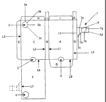
Fig 2 and fig 9 discloses two blanks for forming two
packages or sleeves 1 according to said two basic
embodiments. The panels will be denoted with the
reference numerals A-K. Panel A is also denoted bottom
panel. Panel B is also denoted first side panel. Panel C
is also denoted top panel. Panel D is also denoted first
portion of a second side panel. Panel E is also denoted a
second portion of the second side panel. Panel F is also
denoted reinforcement panel.
The panels A-F are foldable in relation to each
other along a number of fold lines L1-L4 and L6. These
fold lines are also denoted first to fourth fold lines
and sixth fold line.
Panel A and panel B are foldable in relation to each
other about fold line L1 forming a hinge between the
panel A and panel B. Similarly, panel B and C are
connected to each other along fold line L2, panel C and E
along fold line L3, panel A and D along fold line L4 and
panel C and F along fold line L6.
The blank is formed from a paperbased packaging
material. The packaging material may be provided with a
polymer coating. This coating will make the material more
tear-resistant and more resistant to handling by a user
and it will aid in giving the packaging material a
spring-back function. The fold lines are formed by a
creasing operation, which is well known in the art and
will not be described in detail. In an embodiment the
insert 2 is formed from a similar material. As will be
CA 02586270 2007-05-02
WO 2006/068602 PCT/SE2005/001982
19
described later the spring-back function is a relevant
feature especially when it comes to designing the insert
2. The package and/or the insert may also be formed by a
polymer-based material. Such a polymer material may be
formed in one or several layers of the same polymer
material or different polymer materials.
The panels A-F will be folded along said fold lines
L1-L4, and L6 and form a sleeve 1 having a rectangular
cross-section. Panel F will initially be folded and
adhesively be attached to panel C such that panel F will
be located inside the sleeve 1. The reinforcement panel F
may cover the inside of the top panel C completely or
partly. In the figures, showing the sleeve 1, panel F has
been left out in order to make the drawings clear. Panels
H-K will also be folded along fold lines as shown in
fig 2 and fig 9. First, panels I and K will be folded
inwardly and then panel J or H will be folded onto panels
I and K and then the remaining panel H or J will be
folded to finalise the formation of an end wall of the
sleeve 1.
As can be noted in fig 2 and fig 9 the blank is not
provided with any panels adapted to form a front wall of
the sleeve 1. The insert 2 is provided with two panels 2a
and 2b adapted to be folded onto each other about two
fold lines separated by a third panel 2c. This third
panel 2c is adapted to form the missing end wall of the
package 1.
The two blanks are also provided with a panel G
adapted to be folded about a fold line L9 into the sleeve
1. The insert 2 is provided with a corresponding panel 2d
adapted to be refolded backwardly when the insert 2 is
inserted in the sleeve 1. When the insert 2 is pulled
outwardly from the sleeve 1, panel 2d will follow the
bottom panel A of the sleeve 1 and enter into the angle
formed by the bottom panel A and panel G. When the panel
2d hits fold line L9 it need to be unfolded to allow
further removal of the insert 2 from the sleeve 1, but
CA 02586270 2007-05-02
WO 2006/068602 PCT/SE2005/001982
since the two panels 2d and G both have an extension
perpendicular to their respective fold lines being larger
than the height of the sleeve 1 they cannot be unfolded
by just pulling the insert 2 outwardly. Thus, the insert
5 2 is prevented from being removed completely from the
sleeve 1.
The top panel C is provided with a cut-out 3a shaped
as an oval. The portion of panel C within the cut-out 3a
will when pushed be folded into the sleeve 1 along a fold
10 line 3b (creased or imaginary) extending between the ends
3c and 3d of the cut-out. Panel F is provided with a
complete cut-out forming an opening 4 allowing the thus
shaped push-button 3 enter into the sleeve 1.
As shown in fig 1-2 and fig 8-9, the blank is
15 provided with cut-outs 5 and 6 between panel C and F and
between panel A and G. These cut-outs will form grip-
openings of the sleeve 1 making it possible to pull the
insert 2 out of the sleeve 2 with simple finger-grip.
In accordance with a first basic embodiment, the
20 blank and thus also the sleeve 1 is provided with a
locking member 7 attached to panel D. As shown in fig 2,
the locking member 7 may also be attached to the
reinforcement panel F. It should also be noted that it
may be formed as a separate member attached directly to
the top and bottom panels as will discussed in detail
below.
The locking member is divided into four panels 7a-d
divided by three fold lines 7e-g. The focking member 7 is
connected to panel D along a fold line L5, also denoted
fifth fold line. In the alternative, the locking member 7
is connected to reinforcement panel F along a fold line
L7, also denoted seventh fold line.
Fig 5-7 shows that panel 7d, also denoted fastening
panel, is fastened to the bottom panel C such that the
fold line 7g will follow fold line L3 between the bottom
panel C and panel E.
CA 02586270 2007-05-02
WO 2006/068602 PCT/SE2005/001982
21
When the blank is formed as a rectangular sleeve 2,
the locking member will extend as a broken arch into the
sleeve 1. The distance between corner lb to corner la and
from corner la to fold line 7e, also denoted eighth fold
line L8, is compared to the distance from fold line 7e to
fold line 7f and from fold line 7f to corner lb. If the
two distances are equal to each other the locking member
7 can collapse and allow the sleeve 1 to be flat-laid.
The panel 7a has an extension such that fold line 7f is
located further into the cross-section than the point
where fold line 7e, L8 is located. The panel 7c is not
fastened to the inside of the top panel C. The panel 7c
could according to an alternative embodiment be separated
from panel D and instead be fastened to the inside of the
top panel C. The point 7b from which the locking member 7
extends in an arc is also denoted first position. As
shown in fig 2 the first position 7b is located a
distance dl from the first corner la. It has also been
discussed above that the first point 7b and the second
point 7g, also denoted second position, may be translated
along the top panel C and the bottom panel A such that
the second position also is displaced a distance d2 from
the second corner lb. It is also discussed above that the
first position could be considered to be the connection
of the locking member 7 to the panel D. Panel 7a is also
denoted first portion, panel 7b is also denoted second
portion and panel 7c is also denoted third portion of the
locking member 7.
In accordance with another embodiment, the locking
member 7 is provided with an additional fold line 7e' as
disclosed in fig 15. In fig 15, only a limited number of
reference numerals are noted down, since the blank
corresponds to the blank in fig 2 with a slight
difference when it comes to the design of the locking
member 7. The additional fold line 7e' extends close to
and in parallel with fold line 7e. The two fold lines 7e
and 7e' could also be formed as a single fold line having
CA 02586270 2007-05-02
WO 2006/068602 PCT/SE2005/001982
22
an transverse extension (across its longitudinal
extension) corresponding to the two fold lines 7e and
7e'. With the extended or double fold line it is possible
to form the locking member 7 such that the arcuate
extension is optimised with respect to the locking
function and still may be completely flat-laid. One of
the fold lines 7e, 7e' is located at the location which
will fulfil the above discussed distance relationships
such that the locking member 7 may be flat-laid and the
other fold line 7e', 7e is located such that the locking
member 7 will extend into the cross-section in the
desired or optimised manner. If the location of the fold
line 7e giving the flat-laying possibility results in a
satisfactory extension of the locking member 7 into the
cross-section when the package is erected it is
sufficient to use only one fold line 7e as disclosed in
the embodiment of fig 2. Of course the additional or
transversely extended fold line 7e, 7e' may be used when
the locking member 7 is formed as a separate member, an
extension of the side panel portion D, as an extension of
the reinforcement panel F, as a cut-out in the
reinforcement panel F or as a cut-out in the top panel C.
The insert 2 is provided with a locking tab 2e
foldable in relation to the insert 2 along a fold line 2g
(see fig 3 and fig 4). The trailing edge 2e' of the
locking tab 2e and the angle of the folding line 2g are
interrelated such that the leading edge 2e " will
perpendicular to the sliding direction. The leading edge
2e'' of the locking tab 2e is formed as an arch in order
to form a slanted surface abutting the locking member 7
when the insert 2 is inserted into the sleeve 1. The
slanted surface 2e'' will make the locking tab 2e be
refolded more and more as the insert 2 is inserted into
the sleeve 1, such that the locking tab 2e finally may
pass behind the locking member 7 and spring-back behind
it. This situation is shown in fig 7. The locking member
CA 02586270 2007-05-02
WO 2006/068602 PCT/SE2005/001982
23
7 is also provided with a slanted leading edge for
facilitating insertion of the insert 2.
In order to release the insert from the locking
mechanism the push-button 3 is pushed into the sleeve 1
and folds the locking tab 2e of the insert 2 to the basic
plane of the insert 2 such that the locking tab 2e once
again may pass the locking member 7. This situation is
shown in fig 5.
In accordance with a second basic embodiment, the
blank and thus also the sleeve 1 is provided with a
locking member 8. The locking member 8 is attached to the
panel D along a fold line L5 also denoted fifth fold
line. The locking member has two central panels 8a and 8b
and a fastening panel 8c. The fastening panel 8c is
adapted to be fastened to panel E as shown in fig 12 and
fig 14. Panel 8c is connected to panel 8b along a fold
line 8d. The distance between fold line L5 and the fold
line 8d is larger than the distance between fold line L2
and L3, i.e. the width of the top panel C. Thus, when the
sleeve 1 is erected the locking member 8 is forced to
form an arc-shaped extension into the cross-section of
the sleeve 1 as shown in fig 13 and fig 14.
In fig 14 the sleeve is flat-laid by translating the
top surface C to the right in relation to the bottom
surface A. This will result in that the geometrical line
connecting fold line L3 with fold line L5 will rotate
from being essentially 45 outwardly from the package to
being essentially vertical. When considering the length
of the locking member 8 and the top surface C, the
available length of the top surface C will during this
flat-laying be extended compared to the locking member 8
an amount corresponding to the difference in translation
between the fold lines L3 and L5.
At the corner 1b' being refolded the geometrical
line connecting fold line 8d and fold line L2 will change
from being directed essentially 45 outwardly to about
horizontally. Thus, also at this corner will the outer
CA 02586270 2007-05-02
WO 2006/068602 PCT/SE2005/001982
24
move more than the member, but the difference is smaller
compared to the difference at the opposite corner 1a.
At the fold line being refolded (at corner 1b') the
change due to fold line relative displacement will be the
fold line distance (distance after flat-laying) minus
sin45 of the fold line distance (distance before flat-
laying) in favour of the outer material. At the flat laid
fold line (corner la) the change will be sin45 of the
fold line distance (distance before flat-laying) minus
zero (distance after flat-laying) in favour of the outer
material. Thus, the available length will increase about
sin45 -(1-sin45 ), i.e. about 0.4 of the fold line
distance. It should be noted that the fold line distance
is in the same order as the material thickness.
Geometrically the fold line distance is about squareroot
of 2 times the material thickness. These phenomena will
occur irrespective of the flat-laying direction.
Moreover, since the upper left corner la will pivot
about the left lower corner lc being formed by the inner
material of the left side D and the upper right corner
lb' will pivot about the right lower corner 1d being
formed by the outer material B of the right side, the
geometrical lever arms will make the inner left corner
move less than the inner right corner and make the outer
left corner move more than the outer right corner. Thus,
the outer material will experience a geometrical
extension compared to the inner material.
Thus, these phenomena act together when the sleeve
is collapsed in the way denoted by the arrows W in
fig 14. The locking member 8 will allow flat-laying of
the sleeve 1 if the additional distance between fold line
8d and L5 compared to the width of the top panel C is
equal the above described experienced lengthening of the
top panel C.
The locking member 8 is provided with two through-
going openings 8e and 8f. Insert 2 according to the
second embodiment is provided with two locking tabs 2e
CA 02586270 2007-05-02
WO 2006/068602 PCT/SE2005/001982
and 2f in the same manner as in the first embodiment. The
locking tabs 2e and 2f are foldable about to fold lines
2g and 2h. When the insert 2 is inserted into the sleeve
1 the locking tabs 2e and 2f will spring-back into the
5 openings 8e and 8f and prevent the insert 2 from being
pulled out of the sleeve 1.
The locking tabs 2e and 2f are provided with two
trailing edges 2e' and 2f'. The openings 8e and 8f are
each provided with a trailing edge 8e' and 8f' slightly
10 slanted from being perpendicular to the sliding direction
N. The angle of the fold lines 2g and 2h, the angle of
the trailing edges of the locking tabs 2e' and 2f' and
the trailing edges 8e' and 8f' of the openings 8e and 8f
are chosen such that if a user starts pulling the insert
15 2 out of the sleeve 1, without pushing the button 3
first, the locking tabs 2e and 2f will at least partly
pass the trailing edges 8e' and 8f' in the sliding
direction. This results in that when the user push the
button 3, the locking tabs 2e and 2f will not be allowed
20 to be folded beneath the locking member 8. Thus, the user
must push the insert back in again and then push the
button before the insert 2 may be pulled out. Similarly,
as in the first embodiment, the locking tabs 2e and 2f
are provided with curved leading edges and the locking
25 member is provided with a slanted leading edge. The
locking function of the first embodiment may also be
provided with this additional feature of forcing the user
to push the button first. This is accomplished in the
same manner as in the second embodiment, by slanting the
trailing edge of the locking tab 2e compared to the
trailing edge of the locking member. Fig 13 shows how the
push-button 3 pushes the locking tabs 2e and 2f back
through the openings 8e and 8f, thus allowing the insert
2 to be pulled out of the sleeve 1.
As discussed above the locking member 8 may be
lowered in the cross-section by lowering the fold lines
L5 and 8d in relation to the corners la and 1b' along the
CA 02586270 2007-05-02
WO 2006/068602 PCT/SE2005/001982
26
distances dl and d2. In order to further improve the
experienced lengthening of the top panel C, fold line L5
may be lowered slightly more than fold line 8d.
As shown in the figures, the insert 2 may be formed
as a so-called blister-pack carrying some kind of
pharmaceuticals. It could however, be used to carry any
kind of goods that you want to protect and perhaps make
it difficult for kids to get access to. Thus, it could be
used for razor blades, chemical substances or the like.
The package could also be used for candy or other kind of
small articles. The package offers the possibility to
store such items in a child-proof manner. It is also
beneficial to use such a package in order to keep small
items within the package when the package is carried in a
pocket or a purse. The locking function will prevent the
package from being opened by mistake and will thus
prevent chewing gums or throat pastilles from falling out
of the package.
It should also be noted that in the case of a
reinforcement panel F being folded back an attached to
the inside of the top panel C, the reinforcement panel F
may be provided with a cut-out at the location where the
locking member 7 otherwise would abut the reinforcement
panel F. This way the locking member 7 will abut the top
panel C even if there is a reinforcement panel F.
Consequently, the space available for the locking member
7 will not be affected by the presence of any
reinforcement member F.
It should also be noted that the package or blank
might of course be provided with more than one locking
member of the kind described above.
Furthermore, it should also be noted that the
designs disclosed in the above description only allow the
package to be opened if the button is pushed to release
the locking member before the insert is pulled outwardly
at all. It is also contemplated to have the locking
member and locking tab formed with edges being
CA 02586270 2007-05-02
WO 2006/068602 PCT/SE2005/001982
27
perpendicular to the sliding direction and thus arrive in
a design allowing the user to first pull the insert
outwardly and thereafter push the button after realising
that the insert is locked and still allowing the locking
tab to pass the locking member. Other angles of the edges
of the locking elements are also contemplated.