Language selection

Search

Patent 2586372 Summary

Third-party information liability

Some of the information on this Web page has been provided by external sources. The Government of Canada is not responsible for the accuracy, reliability or currency of the information supplied by external sources. Users wishing to rely upon this information should consult directly with the source of the information. Content provided by external sources is not subject to official languages, privacy and accessibility requirements.

Claims and Abstract availability

Any discrepancies in the text and image of the Claims and Abstract are due to differing posting times. Text of the Claims and Abstract are posted:

  • At the time the application is open to public inspection;
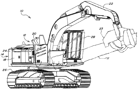
  • At the time of issue of the patent (grant).
(12) Patent: (11) CA 2586372
(54) English Title: LOG DEFLECTOR WITH REMOVABLE ACCESSORY PORTION AND ASSOCIATED METHOD
(54) French Title: DEFLECTEUR DE GRUME DOTE D'UNE PORTION ACCESSOIRE, ET METHODE CONNEXE
Status: Granted
Bibliographic Data
(51) International Patent Classification (IPC):
  • A01G 23/00 (2006.01)
  • E02F 9/24 (2006.01)
(72) Inventors :
  • KOT, ALEKSANDER (Canada)
  • PREDA, MARIN (Canada)
  • FENGLER, ADRIAN M. (Canada)
  • WILKINSON, WILLIAM MARK (Canada)
(73) Owners :
  • DEERE-HITACHI SPECIALTY PRODUCTS (Canada)
(71) Applicants :
  • DEERE-HITACHI SPECIALTY PRODUCTS (Canada)
(74) Agent: NORTON ROSE FULBRIGHT CANADA LLP/S.E.N.C.R.L., S.R.L.
(74) Associate agent:
(45) Issued: 2015-06-30
(22) Filed Date: 2007-04-24
(41) Open to Public Inspection: 2008-08-22
Examination requested: 2012-02-15
Availability of licence: N/A
(25) Language of filing: English

Patent Cooperation Treaty (PCT): No

(30) Application Priority Data:
Application No. Country/Territory Date
11/677,835 United States of America 2007-02-22

Abstracts

English Abstract

A forestry work machine comprises a carrier and a log deflector for deflecting away from the carrier a log held by the forestry work machine. The log deflector comprises a base portion attached to a side of the carrier and an accessory portion projecting laterally outwardly from and removably attached to the base portion. An associated method is disclosed.


French Abstract

Une machine de travail forestier comprend un porte-bûches et un déflecteur de bûches pour détourner dun porte-bûches une bûche tenue par la machine de travail forestier. Le déflecteur de bûches comprend une partie de base fixée à un côté du porte-bûches et une partie accessoire qui sétend latéralement vers lextérieur de la partie de base et fixée à celle-ci de manière amovible. Une méthode associée est décrite.

Claims

Note: Claims are shown in the official language in which they were submitted.


1. A forestry work machine, comprising:
a carrier comprising a front having a boom extending therefrom, a rear, and
laterally
opposite sides, and
a log deflector for deflecting away from the carrier a log held by the
forestry work
machine, the log deflector comprising a laterally extending panel attached to
the carrier and
positioned at one of the sides of the carrier and an accessory portion
projecting laterally
outwardly from the panel so as to extend the log deflecting capability of the
log deflector
laterally beyond the panel and removably attached to the panel with at least
one fastener of the
log deflector such that the accessory portion is removable from the panel to
reduce a width of the
forestry work machine and re-attachable to the panel, the accessory portion
comprises a post and
a post mount removably attached to the panel with the at least one fastener,
and the post is
attached to the post mount so as to angle upwardly and laterally outwardly
away from the panel,
the post mount comprises a first wing removably attached to the panel along a
length of a top
edge of the panel and a second wing removably attached to the panel along a
length of a laterally
outer side edge of the panel.
2. The forestry work machine of claim 1, wherein the at least one fastener
comprises a
bolt.
3. The forestry work machine of claim 1, wherein the at least one fastener
comprises a
plurality of fasteners removably attaching the accessory portion to the panel.


4. The forestry work machine of claim 1, wherein said first wing and said
second wing
join at a junction, said junction being located at a laterally outward corner
of said panel.
5. The forestry work machine of claim 1, wherein the first and second wings
join to
define a junction from which the post angles upwardly and laterally outwardly,
the junction
located at a laterally outer corner of the panel.
6. The forestry work machine of claim 5, wherein the at least one fastener
comprises a
first fastener removably attaching the first wing to the panel along the top
edge thereof and a
second fastener removably attaching the second wing to the panel along the
side edge thereof.
7. The forestry work machine of claim 1, wherein the accessory portion is
generally Y-
shaped.
8. The forestry work machine of claim 1, wherein the accessory portion is
located at a
laterally outer corner of the panel.
9. The forestry work machine of claim 1, wherein the post mount is
positioned at an
upper, laterally outward corner of the panel such that the post extends
upwardly and laterally
outwardly away from the corner.
10. The forestry work machine of claim 5, wherein the panel is upright and
comprises a
periphery comprising the top edge, the laterally outer side edge, a laterally
inner side edge, and a
6


bottom edge, the laterally inner and outer side edges extend between the top
and bottom edges,
the laterally outer corner is positioned between the top edge and the
laterally outer side edge, the
panel comprises a front face surrounded by the periphery, and portions of the
first and second
wings are fastened to the front face,
11. The forestry work machine of claim 1, wherein the carrier comprises a
carriage, and
super-structure rotatably mounted on the carriage, and the boom attached to
the super-structure,
and the log deflector is mounted on the super structure laterally opposite
from a cab of the super-
structure.
7

Description

Note: Descriptions are shown in the official language in which they were submitted.


CA 02586372 2007-04-24

LOG DEFLECTOR WITH REMOVABLE ACCESSORY PORTION AND
ASSOCIATED METHOD

Field of the Disclosure
[0001] The present disclosure relates log deflectors provided onboard forestry
work
machines.

Background of the Disclosure
[0002] Forestry work machines, such as forestry swing machines, may include a
log deflector (also known as a log guard). Such a log deflector is used to
deflect
away from a carrier of the forestry work machine a log held by the forestry
work
machine. In this way, the log deflector reduces the risk that the log will
strike the
carrier.
[0003] Typically, the log deflector is located on a side of the carrier.
However, a
projecting portion of the deflector extending laterally outwardly relative to
the carrier
typically cannot be removed, adding to the overall width of the machine and
reducing
versatility and serviceability.

Summary of the Disclosure
[0004] According to the present disclosure, there is provided a forestry work
machine. The forestry work machine comprises a carrier and a log deflector for
deflecting away from the carrier a log held by the forestry work machine. The
log
deflector comprises a base portion attached to a side of the carrier and an
accessory
portion projecting laterally outwardly from and removably attached to the base
portion. An associated method is disclosed.
[0005] The removability feature of the accessory portion facilitates repair,
replacement, servicing, and versatility for the end user. In addition, since
the
accessory portion may represent the widest point on the machine, removal of
the
accessory portion may enhance use and/or transport of the machine in
relatively
narrow places.
[0006] The above and other features will become apparent from the following
description and the attached drawings.


CA 02586372 2007-04-24

Brief Description of the Drawings
[0007] The detailed description of the drawings refers to the accompanying
figures
in which:
[0008] FIG. 1 is a perspective view of a forestry work machine with a log
deflector
mounted to the right side of the machine;
[0009] FIGS. 2a and 2b are perspective and front elevation views,
respectively,
showing the log deflector having a base portion and an accessory portion
projecting
from and removably attached to the base portion; and
[0010] FIGS. 3a and 3b are perspective and front elevation exploded views,
respectively, showing removal of the accessory portion from the base portion.
Detailed Description of the Drawings
[0011] Referring to FIG. 1, an exemplary forestry work machine 10 has a log
deflector 12 for deflecting away from a carrier 14 of the machine 10 a log 11
held by
the machine 10. The log deflector 12 may comprise a base portion 16 attached
to a
side 18 (e.g., right side in FIG. 1) of the carrier 14 and an accessory
portion 20
projecting laterally outwardly from and removably attached to the base portion
16.
[0012] The forestry work machine 10 may be, for example, a forestry swing
machine. In such a case, an articulated boom 22 for maneuvering a work tool 22
(e.g., a tree harvester head) at the end thereof may be attached to a super-
structure
24 rotatably mounted on a carriage 26, the super-structure 24 and the carriage
26
exemplarily providing the carrier 14. The log deflector 12 may be mounted on
the
side of the carrier 26 opposite from a cab 28 for blocking a log 11 held by
the work
tool 22 from impacting the chassis 30 of the super-structure 24.
[0013] Referring to FIGS. 2a and 2b, the log deflector 12 is shown with the
accessory portion 20 attached to the base portion 16. A number of fasteners 32
(e.g., four) may removably attach the accessory portion 20 to the base portion
16.
[0014] The base portion 16 may have a panel 34 and a hand rail 36 fixed
thereto
behind the panel 34. The panel 34 is attached to the carrier side 18 so as to
extend
laterally outwardly therefrom to provide protection for the super-structure
24. A
number larger slots 38 and smaller slots 40 may be formed in the panel 34 to
reduce
wind resistance, among other possible uses.
[0015] The accessory portion 20 may have a post 42 and a post mount 44
2


CA 02586372 2007-04-24

removably attached to the panel 34 of the base portion 16. The post 42 may be
attached to the post mount 44 so as to angle upwardly and laterally outwardly
away
from a corner 46 of the panel 34.
[0016] The post mount 44 may comprise a first wing 48 removably attached to
the
panel 34 along a top edge 50 of the panel 34 and a second wing 52 removably
attached to the panel 34 along a laterally outer side edge 54 of the panel 34.
The
first and second wings 48, 52 may join to define a junction 56 from which the
post 42
angles upwardly and laterally outwardly. As such, the accessory portion 20 may
be
generally Y-shaped. When the accessory portion 20 is attached to the base
portion
16, the junction 56 may be located at the laterally outer corner 46 of the
panel.
[0017] A number of fasteners 32 may be used to removably attach the first wing
48
to the panel 34 along the top edge 50 and the second wing 52 to the panel 34
along
the side edge 54. lllustratively, there may be two fasteners 32 for each wing
48, 52.
To receive each fastener 32, there may be corresponding fastener-receiving
holes
58 (FIGS. 3a and 3b) formed in the wings 48, 52 and the panel 34 along the
edges
50, 54. The fasteners 32 may be bolts, pins, or the like.
[0018] A hole 60 may be formed in the post 42 near the junction 56. This hole
60
may be used by a lifting device for lifting the accessory portion 20 during
manufacturing or removal and re-attachment of the accessory portion 20.
[0019] The accessory portion 20 may be made of, for example, steel plates
formed
and welded to one another.
[0020] In operation, the accessory portion 20 may be joined to the panel 34 by
extending the fasteners 32 through the respective fastener-receiving holes 58.
The
accessory portion 20 may be removed from the panel 34 by removing the
fasteners
32 from the holes 58. Removal may involve removing fasteners 32 from each of
the
wings 48, 52 enabling removal of the post mount 44 from the panel 34. The post
mount 44 may be removed from the panel 34 by removal of the first wing 48 from
the
top edge 50, the second wing 52 from the side edge 54, and the junction 56
from the
corner 46. Afterwards, the accessory portion 20 may be re-attached to the
based
panel 34.
[0021] While the disclosure has been illustrated and described in detail in
the
drawings and foregoing description, such illustration and description is to be
considered as exemplary and not restrictive in character, it being understood
that

3

I
CA 02586372 2007-04-24

illustrative embodiments have been shown and described and that all changes
and
modifications that come within the spirit of the disclosure are desired to be
protected.
It will be noted that alternative embodiments of the present disclosure may
not
include all of the features described yet still benefit from at least some of
the
advantages of such features. Those of ordinary skill in the art may readily
devise
their own implementations that incorporate one or more of the features of the
present
disclosure and fall within the spirit and scope of the present invention as
defined by
the appended claims.

4

Representative Drawing
A single figure which represents the drawing illustrating the invention.
Administrative Status

For a clearer understanding of the status of the application/patent presented on this page, the site Disclaimer , as well as the definitions for Patent , Administrative Status , Maintenance Fee  and Payment History  should be consulted.

Administrative Status

Title Date
Forecasted Issue Date 2015-06-30
(22) Filed 2007-04-24
(41) Open to Public Inspection 2008-08-22
Examination Requested 2012-02-15
(45) Issued 2015-06-30

Abandonment History

There is no abandonment history.

Maintenance Fee

Last Payment of $473.65 was received on 2023-03-01


 Upcoming maintenance fee amounts

Description Date Amount
Next Payment if small entity fee 2024-04-24 $253.00
Next Payment if standard fee 2024-04-24 $624.00

Note : If the full payment has not been received on or before the date indicated, a further fee may be required which may be one of the following

  • the reinstatement fee;
  • the late payment fee; or
  • additional fee to reverse deemed expiry.

Patent fees are adjusted on the 1st of January every year. The amounts above are the current amounts if received by December 31 of the current year.
Please refer to the CIPO Patent Fees web page to see all current fee amounts.

Payment History

Fee Type Anniversary Year Due Date Amount Paid Paid Date
Application Fee $400.00 2007-04-24
Registration of a document - section 124 $100.00 2008-04-22
Maintenance Fee - Application - New Act 2 2009-04-24 $100.00 2009-04-06
Maintenance Fee - Application - New Act 3 2010-04-26 $100.00 2010-04-08
Maintenance Fee - Application - New Act 4 2011-04-25 $100.00 2011-04-01
Request for Examination $800.00 2012-02-15
Maintenance Fee - Application - New Act 5 2012-04-24 $200.00 2012-04-02
Maintenance Fee - Application - New Act 6 2013-04-24 $200.00 2013-04-02
Maintenance Fee - Application - New Act 7 2014-04-24 $200.00 2014-04-01
Final Fee $300.00 2015-03-09
Maintenance Fee - Application - New Act 8 2015-04-24 $200.00 2015-03-31
Maintenance Fee - Patent - New Act 9 2016-04-25 $200.00 2016-04-18
Maintenance Fee - Patent - New Act 10 2017-04-24 $250.00 2017-04-17
Maintenance Fee - Patent - New Act 11 2018-04-24 $250.00 2018-04-23
Maintenance Fee - Patent - New Act 12 2019-04-24 $250.00 2019-04-22
Maintenance Fee - Patent - New Act 13 2020-04-24 $250.00 2020-04-01
Maintenance Fee - Patent - New Act 14 2021-04-26 $255.00 2021-03-31
Maintenance Fee - Patent - New Act 15 2022-04-25 $458.08 2022-03-02
Maintenance Fee - Patent - New Act 16 2023-04-24 $473.65 2023-03-01
Owners on Record

Note: Records showing the ownership history in alphabetical order.

Current Owners on Record
DEERE-HITACHI SPECIALTY PRODUCTS
Past Owners on Record
FENGLER, ADRIAN M.
KOT, ALEKSANDER
PREDA, MARIN
WILKINSON, WILLIAM MARK
Past Owners that do not appear in the "Owners on Record" listing will appear in other documentation within the application.
Documents

To view selected files, please enter reCAPTCHA code :


To view images, click a link in the Document Description column. To download the documents, select one or more checkboxes in the first column and then click the "Download Selected in PDF format (Zip Archive)" or the "Download Selected as Single PDF" button.

List of published and non-published patent-specific documents on the CPD .

If you have any difficulty accessing content, you can call the Client Service Centre at 1-866-997-1936 or send them an e-mail at CIPO Client Service Centre.


Document
Description 
Date
(yyyy-mm-dd) 
Number of pages   Size of Image (KB) 
Representative Drawing 2008-08-07 1 28
Abstract 2007-04-24 1 10
Description 2007-04-24 4 170
Claims 2007-04-24 2 77
Drawings 2007-04-24 5 131
Cover Page 2008-08-14 1 56
Claims 2014-05-12 3 76
Claims 2014-08-28 3 80
Representative Drawing 2015-06-11 1 27
Cover Page 2015-06-11 1 56
Correspondence 2007-05-25 1 27
Assignment 2007-04-24 3 95
Correspondence 2008-06-06 2 36
Correspondence 2008-05-02 1 17
Correspondence 2008-04-22 2 55
Correspondence 2008-05-02 1 16
Correspondence 2008-04-22 3 126
Assignment 2008-04-22 12 531
Correspondence 2008-09-15 1 19
Assignment 2008-08-26 13 540
Prosecution-Amendment 2012-02-15 2 77
Prosecution-Amendment 2013-07-22 2 58
Prosecution-Amendment 2014-01-22 8 279
Correspondence 2014-02-12 1 19
Prosecution-Amendment 2014-05-12 7 278
Correspondence 2014-07-28 2 70
Prosecution-Amendment 2014-08-28 5 152
Prosecution-Amendment 2014-10-03 3 124
Correspondence 2014-10-03 3 124
Correspondence 2014-10-23 1 23
Correspondence 2014-09-15 1 153
Correspondence 2015-03-09 1 65