Note: Descriptions are shown in the official language in which they were submitted.
CA 02586411 2007-05-03
WO 2006/052868 PCT/US2005/040249
PORTABLE ENTRY SYSTEM AND METHOD
BACKGROUND OF THE INVENTION
1. Field of the Invention
The present invention relates to a portable entry mechanism for use on a
device such as a safe. More particularly, the present invention relates to an
electronic portable entry mechanism that is removable from a safe or vault
when
not in use.
2. Description of the Related Art
Electronic locks have become a popular alternative to mechanical locks
due to their versatility and security. For example, electronic locks allow a
user to
set their own combinations. With the increase in passwords, Personal
Identification Numbers (PINs) and other codes that people need to remember, a
lock combination that is set by the user allows the user to select
combinations
that are easy to remember.
Exemplary electronic locks are shown and described in Gartner, U.S. Pat.
No. 6,786,519, and Gartner, U.S. Pat. No. 6,760,964, both incorporated by
reference herein in their entireties. Electronic locks typically employ an
electromagnetic device, such as a solenoid, operably connected to a circuit
board. The circuit board, upon receiving a predetermined input representing
the
access code, sends an electrical signal to the electromagnetic device, thereby
energizing the device to an "open" state and allowing the safe to be opened.
These electronics are typically powered by a battery, which is either hidden
in the
safe door or in the keypad housing. The Gartner '519 patent discloses a keypad
that includes a battery that can be replaced without opening the safe, and
also
provides a secure connection to internal circuitry to thwart tampering efforts
and
accidental breakage during assembly. The Gartner '964 patent discloses a swing
bolt lock that is operably connected to a plunger-type solenoid. The plunger
engages a locking plate. When the lock is in the locked condition, the locking
plate engages the locking bolt to prevent the swing bolt from pivoting. When a
user enters the correct combination, the plunger disengages the locking plate
so
that the locking plate slides out of engagement with the locking bolt. A
handle
-1-
CA 02586411 2007-05-03
WO 2006/052868 PCT/US2005/040249
connected by a shaft through the outside of the safe drives the boltworks.
Movement of the boltworks acts on the swing bolt and pivots it to the unlocked
position. Because the locking plate is out of engagement with the locking
bolt, it
does not prevent the swing bolt from pivoting thus allowing the user to access
the
safe.
Although the Gartner '519 and '964 patents address many of the previous
shortcomings of electronic locks, it would be desirable to provide a lock that
is
operable with a portable entry device that contains the power supply for
operating
the electromechanical safe lock and that can be stored at a location remote
from
the lock. Further, a portable entry device that is operable only by authorized
users via entry of an authorized user code and that contains a separate lock
security code that mates with a code stored in a lock within a safe would also
be
desirable. If the portable entry device was misplaced or became lost and an
unauthorized user found the portable entry device, the unauthorized user would
not be able to use the device because the unauthorized user would not have the
authorized user code to activate the device.
For example, automatic teller machines ("ATMs") are typically located in
public places and contain large amounts of cash. Even without an access code,
an unauthorized user would have an opportunity to manipulate the keypad on the
safe and open the safe. Consequently, such safes are typically hidden behind a
locked cabinet, giving an additional degree of security. However, if the lock
were
constructed and arranged such that the keypad and power supply were
removable when not in use, further security would be provided. A portable
entry
device including external keypad and internal power supply could be further
protected in an offsite location, such as in another safe or simply carried by
the
authorized user. Thus, a security company tasked with emptying money from a
vault could securely maintain the necessary entry device in a separate safe
and
check the entry device out to authorized security personnel for the limited
time
necessary to access the vault. Not only would the entry device avoid tampering
efforts, if it were somehow lost or stolen, it would be useless without the
authorized user's security code.
-2-
CA 02586411 2007-05-03
WO 2006/052868 PCT/US2005/040249
SUMMARY OF THE INVENTION
The present invention relates to a portable entry device that operates an
electromechanical lock inside, for example, a safe. The portable entry device
is
carried by the user and/or stored at a remote site when the user does not need
to
operate the lock in order to access the safe. This arrangement provides an
added degree of security to the contents of the safe being protected by the
lock.
The portable entry system in accordance with the present invention
includes a hand-held, portable entry device, an electromechanical lock
positioned
within a safe, and a receiving receptacle positioned on the outside of a safe
for
receiving the portable entry device. An optional docking station is also
provided.
The electromechanical lock is typically positioned on the backside of a safe
door
and includes a circuit board and at least one electromagnetic device that is
moveable or otherwise influenced by the circuit board. The portable entry
device
includes a pre-programmed lock security code or codes and an authorized user
code or codes, a power supply therewithin, such as a battery, and a user-
activated interface such as a keypad, fingerprint identification system,
retina
scan, voice-recognition device, electronic signature pad, or the like.
Alternatively,
a global positioning system may be used. If a GPS is installed in the portable
entry device, the device cannot be activated unless the coordinates of the
portable entry device with installed GPS match the coordinates of safe's
location.
The portable entry device is constructed and arranged to communicate with a
circuit board within the electromechanical lock when placed in operating
relationship thereto. Upon input, receipt and verification of the correct
authorization code from the user into the user interface, the device is
activated
and communicates the pre-programmed lock security code to the microprocessor
contained within the electromechanical lock positioned within the safe. If the
microprocessor recognizes and matches the security code, it sends a signal to
the circuit board, which in turns sends a command to the electromagnetic
device.
When the electromagnetic device receives the command, a plunger on the
solenoid disengages the locking bolt, which locks the safe boltworks. A handle
connected by a shaft through the outside of the safe is operably connected to
the
safe's boltworks. A user operating the safe's handle turns the handle.
Movement
of the handle causes the boltworks to act on the locking bolt which retracts
or
-3-
CA 02586411 2007-05-03
WO 2006/052868 PCT/US2005/040249
otherwise moves to the unlocked position thereby allowing the authorized user
to
open the safe. The power supply contained within the portable entry device
provides the necessary electricity to not only the circuit board and user
interface,
but also to the electromagnetic device, which may be a solenoid or a motor. If
a
motor is used, the motor actuates the locking bolt to withdraw or otherwise
retract
from an engaged position, which locks the boltworks to an unengaged position,
which allows the boltworks to move and open the safe. The present invention
may be used with a variety of locking bolts such as a slide bolt, a dead bolt,
a
swing bolt and other locking bolts known to those skilled in the art.
One aspect of the present invention provides a lock system including a
portable entry device that activates an electromechanical lock inside a safe.
The
electromechanical lock includes a locking bolt moveable between an open
position and a closed position. The locking bolt blocks the safe's boltworks.
The
electromagnetic device includes an engaged state and a disengaged state, and
prevents the locking bolt from being moveable to the open position when the
electromagnetic device is in the engaged state. In the disengaged state, the
electromagnetic device allows the locking bolt to move to the open position. A
solenoid-operated plunger, such as disclosed in U.S. Pat. No. 6,786,519, is
one
example of such an electromagnetic device.
The electromechanical lock further includes a circuit board electronically
connected to the electromagnetic device. The circuit board has computer
memory attached thereto that is capable of storing one or more pre-programmed
codes. A processor is also attached to the circuit board and in communication
with the computer memory. The processor is capable of comparing a received
code to at least one of the plurality of codes stored in the computer memory
and
sending a signal that causes the electromagnetic device to change between the
engaged and disengaged states.
The electromechanical lock also includes at least one communication
channel that allows communication between the portable entry device and the
circuit board. Upon verifying that a code is received from an authorized user
using the portable entry device, the circuit board sends a signal that causes
the
electromagnetic device to change between the engaged and disengaged states.
-4-
CA 02586411 2007-05-03
WO 2006/052868 PCT/US2005/040249
An example of a communication channel is a conductor connecting the circuit
board to an electrical contact on an external surface of the electromechanical
lock. Another example of a communication channel is a radio frequency receiver
or transceiver operably connected to the circuit board that controls the
electromagnetic device.
Additionally, the electromechanical lock includes at least one power
channel capable of transferring power from the portable entry device to the
electromagnetic device.
The portable entry device has a housing with a user interface operably
attached to the housing. The user interface may be a variety of devices,
including but not limited to a keypad, a fingerprint, voice or retina
recognition
device, a global positioning system, or an electronic signature recognition
pad.
Each of these user interfaces has unique attributes that make it advantageous
in
different applications.
The portable entry device further includes a power supply contained within
the housing and capable of supplying enough power to the electromechanical
lock to power the circuit board and the electromagnetic device. The power is
delivered to the circuit board through the power channel.
The physical relationship between the electromechanical lock and the
portable entry device can be embodied in various configurations. A durable
configuration includes a handheld device that is relatively rectangular in
shape,
an entire end of which constitutes a male coupling. A receiving receptacle
positioned on the outside portion of the safe door defines a female coupling
sized
to receive the handheld device. When the male coupling end of the portable
entry device is placed in the female coupling, electrical contacts on both
components abut, establishing electrical communication therebetween.
Alternatively, the handheld device could comprise a male USB or serial
connector or the like. A corresponding female port would then be found on the
receiving receptacle. The receptacle then communicates via cable with the
electromechanical lock. Another alternative provides a portable entry device
that
establishes data flow communication and power transfer with the
electromechanical lock without physical contact between the two components
-5-
CA 02586411 2007-05-03
WO 2006/052868 PCT/US2005/040249
and without the need for a receptacle. Isolation transformers are usable to
transfer power without physical contact, while there are many forms of
wireless
data communication useable to relay code data between the portable entry
device and the electromechanical lock. Another alternative provides a portable
entry device that is in power and data flow communication directly with the
electromechanical lock without the need for a receptacle.
Another aspect of the invention provides an optional docking station that
is connectable to a computer. The docking station is constructed and arranged
to
receive the portable entry device and includes a charger operably connected to
the power supply of the portable entry device when the portable entry device
is
received by the docking station. The charger is capable of charging or
recharging the power supply in the handheld device.
The docking station also includes a data link capable of operably
connecting the processor of the portable entry device to a computer when the
portable entry device is in the docking station and the docking station is
connected to a computer. The data link allows data flow communication between
the computer and the processor of the portable entry device.
In an alternative embodiment, the portable entry device may be designed
to operate without the need for a docking station. The portable entry device
may
be directly connectable to a computer capable of charging or recharging the
power supply in the device.
Another aspect of the present invention provides a method of opening a
safe. The method includes providing a safe having a door containing a
receptacle for a portable entry device, boltworks that lock the safe's door,
and an
electromagnetic device contained within a safe, the electromagnetic device in
communication with a lock that prevents the boltworks from being moved into a
retracted position.
A portable entry device containing a pre-programmed user security code
and a pre-programmed lock security code is provided. A user places the
portable
entry device in mating relationship with a receiving receptacle located on a
safe
door and enters a PIN, fingerprint identification, retinal scan, etc. If the
user
security code is correct, the portable entry device activates and sends a
signal to
-6-
CA 02586411 2007-05-03
WO 2006/052868 PCT/US2005/040249
a microprocessor located within the electromechanical lock. The microprocessor
then determines whether the lock security code matches the code stored within
the microprocessor. If the codes match, a signal is transmitted from the
microprocessor to the electromagnetic device activating it and causing it to
disengage the locking bolt allowing the authorized user to turn the safe
handle
and access the safe.
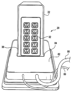
BRIEF DESCRIPTION OF THE DRAWINGS
Figure 1 is a perspective view of an embodiment of a portable entry
device of the present invention;
Figure 2 is a perspective view of an embodiment of a docking station of
the present invention;
Figure 3 is a perspective view of the portable entry device of the present
invention placed in the docking station;
Figure 4 is a perspective view of an embodiment of an electromechanical
lock of the present invention;
Figure 5 is a perspective view of an embodiment of a safe door with a
handle in an open position, the safe door including the portable entry device
and
electromechanical lock of the present invention.
DETAILED DESCRIPTION OF THE INVENTION
Referring now to Figures 1-4, it can be seen that the present invention
includes a portable entry device 20; a docking station 80; an
electromechanical
lock 50 located within, for example, a safe; and a portable entry device
receiving
receptacle 64 located on, for example, the door of a safe 70. The portable
entry
device 20, shown in Figure 1, includes a housing 22 that houses a
microprocessor or microchip 24, computer memory 26 operably connected to the
microchip 24, and a power supply 28 operably connected to the microchip 24.
The internal components 24, 26 and 28 are shown schematically in phantom
lines. The power supply 28 is preferably a rechargeable battery. One skilled
in
the art will realize that the computer memory 26 could be integrated with the
microchip 24. Optimally, microchip 24 and computer memory 26 are components
-7-
CA 02586411 2007-05-03
WO 2006/052868 PCT/US2005/040249
of a circuit board 30.
The portable entry device 20 also includes, on an outer surface, a user
interface 32. The user interface 32 is operably connected to the circuit board
30
such that data flow inputted into the user interface 32 can flow to the
microchip
24. The user interface 32 is embodied in Figure 1 as a keypad. In alternative
embodiments of the present invention, user interface 32 may be a fingerprint
recognition or retinal scan device or other biometric devices. Also on an
external
surface 35 of portable entry device 20 is a plurality of contacts 33, 34. The
contacts 33, 34 allow the portable entry device 20 to communicate in mating
relationship with contacts 56, 57 of receptacle 64 (which in turn communicate
with
electromechanical lock 50) and contacts 85, 86 of docking station 80 (which in
turn communicate with an external power source and a computer storing data).
Contacts 33 are in data flow communication with the microchip 24.
Contacts 34 are electrically connected to the power supply 28 and usable to
supply power to the electro-magnetic device 54 of lock 50 when connected
thereto. Contacts 34 also receive power from the docking station 80 when
connected thereto during a recharging operation. As those skilled in the art
will
appreciate, the number of contacts for power and data communication can vary
and may include one contact each or a plurality of contacts. The contacts 33,
34
shown for data flow communication and power supply are exemplary only and as
those skilled in the art will appreciate may be reversed, may be on the front,
back,
sides or on opposites sides of the portable entry device in any usable
configuration.
Referring now to Figure 2, there is shown optional docking station 80 of
the present invention. Docking station 80 includes a body 82 defining a
receiving
dock 84 sized to receive at least a portion of the portable entry device 20.
The
dock 84 includes data communication and power contacts 85, 86, respectively.
The docking station 80 further includes a data link 88 capable of connecting
the
docking station 80 to a computer. The data link 88 may terminate with a
universal serial bus (USB) connector, fire wire connector, or any connector
usable to connect an external device to a computer. The computer may store
useful information that is uploaded to the portable entry device when the
portable
-8-
CA 02586411 2007-05-03
WO 2006/052868 PCT/US2005/040249
entry device is docked in the docking station 80. For example, useful data
such
as the authorized users for the portable entry device, the events that
transpired
during, for instance, a cash-carrier route such as time of lock openings and
the
personnel associated with the openings may be uploaded.
The docking station 80 has a charging function and a data
communications function. The charging function is used to recharge the power
supply 28 of the portable entry device 20 when the portable entry device 20 is
placed in the dock 84. When placed in the receiving dock 84, the contacts 34
of
the portable entry device 20 are electrically connected to the contacts 86 of
the
docking station 80. At least one of contacts 86 supplies charging power to the
power supply 28 of the portable entry device 20. Again, those skilled in the
art
will appreciate that the number of contacts can be varied without sacrificing
functionality. Power cable 89 connects to an external power supply to maintain
docking station 80 fully charged.
Those skilled in the art will also appreciate that the charging function can
be accomplished by a charger 92 within the docking station 80, or may be
supplied by a charger contained within the computer leaving the docking
station
to serve only as a connector between the power supplied by the computer and
the power supply 28. If the charger 92 is contained within the docking station
80
it may receive electricity from the computer or an external source.
The data communications function establishes data flow between a
external computer and microchip 24 of portable entry device 20 via data link
88.
The data flow is preferably two-way flow allowing the computer to input new
codes into the portable entry device 20 as well as receive data from the
microchip
24 for purposes of record keeping.
Figure 3 depicts the portable entry device of the present invention docked
in docking station 80 with power contacts 34 in communication with contact 86
and data communication contacts 33 in data flow communication with
communication contacts 85.
Referring now to Figure 4, there is shown the second and third
components of the present invention, an electromechanical lock 50 and a
portable entry device receiving receptacle 64. The electromechanical lock 50
-9-
CA 02586411 2007-05-03
WO 2006/052868 PCT/US2005/040249
includes a locking bolt 52, which retracts or otherwise moves between an open
position and a closed position by operation of an electromagnetic element 54,
discussed in detail below. The electromechanical lock 50 could be any
mechanical lock mechanism such as the swing bolt lock disclosed in U.S. Patent
No. 6,786,519 to Gartner. Alternatively, the lock mechanism may be a slide
bolt,
a dead bolt and other locking bolts known to those skilled in the art.
Electromechanical lock 50 includes an electromagnetic device 54, shown
diagrammatically in phantom lines as an exemplary solenoid-operated plunger,
which has an engaged state and a disengaged state. The electromagnetic
element 54 may be a solenoid, which is a linear electromagnetic device. A
motor
or other rotary electromagnetic device may also be employed. A plunger 53 on
the solenoid engages locking bolt 52. When the locking bolt 52 is in its
locked
position, it engages boltworks 55 and prevents boltworks from moving. The
electromagnetic lock 50 is operably attached to the safe's boltworks 55, such
that
the boltworks 51 are prevented from being movable between an open position
and a closed position when the electromagnetic lock 50 is in an engaged state.
In the disengaged state, the electromagnetic lock 50 allows a user to rotate
handle 72 on safe 70 into an open position, as shown in Figure 5.
Receiving receptacle 64 includes a plurality of contacts 56, 57 that are
positioned to electrically interact with the contacts 34, 35 of the portable
entry
device 20, respectively. It can be seen in Figure 4, that the receiving
receptacle
64 is configured to mate with the portable entry device 20 of Figure 1.
Receptacle 64 that is sized to receive housing 22 of the portable entry device
20.
Thus, receptacle 64 constitutes a female coupling and the end 36 proximate the
contacts 33, 34 of the portable entry device 20 constitutes a male coupling.
Contacts 56, 57 are electrically connected to a microchip 58. The
microchip or processor 58 is a component of a circuit board 59 that is either
contained within the electromechanical lock 50 or contained within the safe
that
the lock 50 is securing. Also on the circuit board is computer memory 61,
accessible by the microchip 58. The circuit board 59 is electrically connected
to
at least one of the contacts 57 to form a communications channel 60
therebetween. Furthermore, the circuit board 59 is electrically connected to
at
-10-
CA 02586411 2007-05-03
WO 2006/052868 PCT/US2005/040249
least one of the contacts 56 to form a power channel therebetween. The power
channel 62 further connects the circuit board 59 to the electromagnetic device
54.
In operation, the portable entry device 20 is stored in docking station 80
where data is uploaded into computer memory 26 of microprocessor 24. The
stored data may include information such as any number of authorized user
codes, any number of security codes that correspond to safes located along a
carrier's route, the events that transpired during a cash-carrier route such
as time
of safe openings and the personnel associated with the openings. Upon arriving
at a safe's location, the user would typically first place the portable entry
device
20 in the receiving receptacle 64 located on safe door 70. Contacts 33 and 34
are placed in communication with contacts 57 and 56, respectively and power
communication and data communication is established. The user then enters his
authorized user security code (or scans his retina or applies his fingerprint)
into
the user interface 32 of the portable entry device 20. If the user security
code,
retina or fingerprint matches the pre-programmed information stored within the
portable entry device 20, the portable entry device is activated. Data
communications channel 60 in operating communication with contact 33 relays
the pre-programmed lock security code that is stored within the portable entry
device 20 to microprocessor 58. Upon receiving the code, microprocessor 58
compares the received lock security code to the lock security code stored in
memory 61. If the codes match, microprocessor 58 sends a signal to the
electromagnetic device 54. Use of the power channel 62 may be obviated or
combined with the communications channel 60 in the event that the voltage
required to operate the electromagnetic device 54 is sufficiently small to be
drawn
from the communications channel. Upon receiving a signal from the
microprocessor 58, solenoid 54 causes plunger 53 to retract thereby
disengaging
locking bolt 52. In an alternative embodiment, a motor (not shown) causes a
locking bolt to slide, retract or otherwise move thereby disengaging the
locking
bolt. The user receives an audible signal indicating that the safe may be
opened.
The user operates handle 72, turning it to the unlocked position. Because the
locking bolt 52 is disengaged, handle 72 causes the boltworks to act on the
locking bolt and locking bolt retracts, pivots, slides or otherwise moves
permitting
boltworks 51 to freely move into the open position as shown in Figure 5.
-11-
CA 02586411 2007-05-03
WO 2006/052868 PCT/US2005/040249
It is contemplated that features disclosed in this application can be mixed
and matched to suit particular circumstances. Various other modifications and
changes will be apparent to those of ordinary skill in the art without
departing
from the spirit and scope of the present invention. Accordingly, reference
should
be made to the claims to determine the scope of the present invention.
-12-