Note: Descriptions are shown in the official language in which they were submitted.
CA 02586562 2009-04-07
GAS MICRO BURNER
1. Field of the Invention
This invention relates generally to gas combustion burners. More particularly,
the present
invention relates to an integral gas burner for a smoking article employing
combustion of a
pre-mixed gaseous fuel.
2. Description of the Related Art
Small scale gas combustion burners, such as those used in cigarette lighters,
are well
known in the art. Most cigarette lighters use buoyancy to entrain air for
diffusion
combustion. The fuel vapors and air meet at the point of ignition and burn
instantaneously.
Hence, the fuel and air are not mixed upstream from the point of ignition in
such lighters.
Since no apparatus for pre-mixing is necessary, a diffusion flame lighter may
be quite short
in length. Unfortunately, diffusion flame burners tend to produce soot from
unburned
hydrocarbons and pyrrolitic products that occur due to incomplete combustion
of the gaseous
fuel. Furthermore, flames produced by diffusion burners tend to be unstable
and bend as the
burner is rotated.
The production of a pre-mixed flame in a gas combustion burner is also well
known
in the art. A pre-mixed flame is the product of a combustion process wherein
the fuel is
mixed with air upstream of the point of ignition. By the time the fuel/air
mixture reaches the
point of ignition, a stoichiometrically sufficient amount of oxygen is
available for the
combustion reaction to proceed to near completion. The flame produced by the
pre-mixing
of the fuel and air is stable and will not bend if the burner is rotated.
Furthermore, since the
1
CA 02586562 2009-04-07
fuel/air mixture tends to combust completely, a pre-mixing gas burner produces
little to no
soot or unreacted hydrocarbons. The stoichiometric or oxygen-rich flame
produced in such a
gas burner leaves predominantly C02, H20 and N2 as the only combustion
byproducts.
In the production of a pre-mixed flame, the mixing of the fuel and air prior
to
combustion is usually performed with a venturi, which draws air into the
burner as fuel
passes therethrough. However, the presence of an effective venturi tends to
add to the
overall length of the burner apparatus. In addition, the fuel mass flow rate
requirement of the
burner affects the overall size of the combination of the burner and fuel
storage container.
For example, the smallest fuel flow rate for a butane lighter that sustains a
stable pre-mixed
flame approaches approximately 0.71 mg/s. Reducing the fuel mass flow rate
requirement
thereby allows for a reduction in the overall size of the burner and fuel
storage container.
Reducing the size of the burner and fuel tank expands the scope of possible
applications of
such a burner.
It is, therefore, desirable to provide a gas burner that produces a stable pre-
mixed
flame and that is small enough to be used in a variety of applications, such
as smoking
articles.
SUMMARY OF THE INVENTION
The present invention provides a gas burner that generates a stable pre-mixed
flame
with low fuel mass flow rate requirements.
The present invention also provides a gas burner that may be used for a
smoking
article and that also may be sized smaller than conventional gas lighters.
2
CA 02586562 2009-04-07
The present invention also provides a mixing chamber for a gas burner that
provides
highly efficient mixing of fuel and air in a small volume.
Accordingly, the present invention provides a gas burner, adapted to be
integrally
combined with a smoking article, comprising: a venturi having a nozzle and an
oxygenation
chamber in flow communication with said nozzle, said oxygenation chamber
having at least
one air inlet; a mixing chamber in flow communication with said oxygenation
chamber and
having a frustoconical portion of an inner wall that diverges from said
oxygenation chamber;
at least one permeable barrier in flow communication with said mixing chamber
and being
disposed opposite said oxygenation chamber; and a flame holder in flow
communication
with said permeable barrier, said flame holder including a flame tube in flow
communication
with said flaine holder, said flame tube having an exhaust port and being
adapted to hold said
smoking article.
The present invention also provides a gas burner comprising: a nozzle; an
oxygenation chamber in flow communication with said nozzle; at least one air
inlet in flow
communication with said oxygenation chamber; a mixing chamber in flow
communication
with said oxygenation chamber, said mixing chamber having a frustoconical
inner wall; and,
a flame holder in flow communication with said mixing chamber, said flame
holder having at
least one opening therein; and a flame tube in flow communication with said
flame holder,
said flame tube having an exhaust port.
The present invention also provides a gas burner, integrally combined with a
smoking
article, comprising: a venturi having a nozzle and an oxygenation chamber in
flow
communication with said nozzle, said oxygenation chamber having at least one
air inlet; a
mixing chamber in flow communication with said oxygenation chamber and having
a
3
CA 02586562 2009-04-07
frustoconical portion of an inner wall that diverges from said oxygenation
chamber; at least
one permeable barrier in flow communication with said mixing chamber and being
disposed
opposite said oxygenation chamber; a flame holder in flow communication with
said
permeable barrier: a flame tube in flow communication with said flame holder;
and at least
one exhaust port in said flame tube.
More particularly, the present invention is directed to a burner assembly for
combustion of gaseous fuel. The burner assembly includes a fuel inlet, nozzle,
an
oxygenation chamber with at least one air inlet, a mixing chamber, at least
one permeable
barrier, a flame holder, an optional flame tube with optional exhaust port,
and an optional
burner housing. The fuel inlet connects the burner assembly to the gaseous
fuel storage tank.
An optional flow adjustment mechanism may be attached to the fuel inlet to
regulate the fuel
mass flow rate from a fuel storage container. The nozzle is in flow
communication with the
fuel inlet and affects both the static pressure and the velocity of the fuel
stream passing
therethrough. The nozzle feeds fuel from the fuel inlet to the oxygenation
chamber. The
inner diameter of the nozzle is significantly smaller than that of the fuel
inlet, thereby
accelerating the fuel stream passing therethrough. The static pressure of the
fuel stream
drops as it travels from the constricted nozzle into the larger oxygenation
chamber. At least
one air inlet is disposed in one or more of the walls of the oxygenation
chamber. Air is
drawn into the oxygenation chamber through the air inlet(s) by the reduction
in static
pressure caused by the gaseous fuel entering the oxygenation chamber through
the nozzle.
The size of the nozzle influences the mass flow rate of air drawn into the
venturi tube
through the air inlets.
4
CA 02586562 2009-04-07
A mixing chamber is in flow communication with the oxygenation chamber. The
mixing chamber provides for the efficient mixing of the air and the gaseous
fuel in a
relatively small volume. The mixing chamber has either an inner wall which
includes a
frustoconical section, or a ferrule may be disposed within the mixing chamber
to provide an
inner wall with a frustoconical section. In either case, the interior of the
mixing chamber
expands from the proximal end, which is adjacent to the oxygenation chamber,
to the distal
end. The diverging side wall of the mixing chamber provides an interior space
in which the
fuel and air may efficiently mix. At least one permeable barrier is disposed
downstream of
and in flow communication with the mixing chamber. The permeable barrier may
be
disposed at the outlet of the mixing chamber or be spaced therefrom. The
permeable barrier
may be a porous metal or ceramic plate, or another permeable material or
structure that
inhibits the flow of the fuel/air mixture from the mixing chamber. The
permeable barrier
restricts the flow of the fuel/air mixture and causes a drop in the mixture=s
static pressure.
The result of the flow restriction is recirculation of a portion of the
fuel/air stream within the
mixing chamber. Recirculation eddies tend to form within the mixing chamber
around the
axis of the flow stream. This recirculation provides for a more complete
mixing of the
fuel/air stream prior to ignition.
A flame holder is disposed in the gas burner downstream of and in flow
communication with the permeable barrier(s). The flame holder includes at
least one
opening therein which further restricts the fuel/air stream flow. An ignition
means is
disposed downstream of the flame holder and precipitates the combustion of the
fuel/air
stream upon activation. The flame holder prevents the flame generated by the
combustion of
5
CA 02586562 2009-04-07
the fuel/air stream from flashing back through the burner. An optional flame
tube with an
optional exhaust port may also be provided. The flame tube localizes the flame
and prevents
diffusion of air to it. The flame generated by the burner is a stable pre-
mixed flame that has
at least a stoichiometrically sufficient amount of air for complete combustion
of the fuel.
The optional exhaust port allows combustion gases to vent from the flame tube.
This port or
aperture prevents the flame from extinguishing when a smoking article is
inserted into the
flame tube while no gas is being drawn through the smoking article.
The flame generated within the gas burner will not bend and is, thus,
unaffected by
the orientation of the burner. Furthermore, the combustion process carried out
in the burner
does not require diffused air to assist in complete reaction; therefore, the
flame may be
enclosed within a flame tube. Enclosing the flame allows the gas burner to be
employed in a
variety of applications, such as an integral cigarette lighter, in which other
flames, which rely
on diffusing air, would be inappropriate. Optionally, the flame tube may have
an exhaust
port so that when the gas micro burner is integrally combined with a smoking
article, a
constant draw on the smoking article is not required to keep the gas micro
burner lit. The
burner generates a stable, pre-mixed flame with a significantly smaller fuel
flow rate than
required by conventional cigarette lighters. For example, conventional butane
lighters
generally require fuel mass flow rates of at least 0.71 mg/s, whereas the gas
burner of the
present invention produces a sustainable pre-mixed flame with a fuel flow rate
in the range of
approximately 0.14 mg/s - 0.28 mg/s. At this specified range, a lighter
utilizing the gas
burner of the present invention generates a heat output of approximately 6 -
12 Watts. Such
power output allows such a gas burner to be used in an integral lighter for a
smoking article.
6
CA 02586562 2009-04-07
It will become apparent that other objects and advantages of the present
invention
will be obvious to those skilled in the art upon reading the detailed
description of the
preferred embodiment set forth hereinafter.
BRIEF DESCRIPTION OF THE DRAWINGS
FIG. 1 is a perspective view of the gas burner of the present invention with
selected
portions shown in phantom lines.
FIG. 1 a is a perspective view of the gas burner of FIG. 1 with a cigarette
inserted
therein and with selected portions shown in phantom lines and other selected
portions in
cutaway.
FIG. lb is a perspective view of the gas burner of FIG. la with a cigarette
inserted
therein and showing an exhaust port in the flame tube.
FIG. 2 is a cross-sectional view of the gas burner taken along line 2-2of FIG.
1.
FIG. 3 is a cross-sectional view of the gas burner of the present invention
attached to
a fuel storage container and enclosed in a burner housing.
FIG. 4 is a cross-sectional view of another embodiment of the gas burner of
the
present invention.
FIG. 5 is an exploded view of yet another embodiment of the gas burner of the
present invention.
FIG. 5a is an exploded view of yet another embodiment of the gas burner of the
present invention.
7
CA 02586562 2009-04-07
FIG. 6 is an end on view of the burner housing of the gas burner of FIG. 5.
FIG. 7 is a cross-sectional view of the burner housing of FIG. 6 taken along
line 7-7.
FIG. 7a shows the burner housing of FIG. 7 having an exhaust port.
FIG. 8 is an end on view of the nozzle of the gas burner of FIG. 5.
FIG. 9 is a side view of the nozzle of FIG. 8 with selected portions shown in
phantom
lines.
FIG. 10 is a cross-sectional view of the nozzle of FIG. 8 taken along lines 10-
10.
FIG. 11 is an expanded view of area 10 of the nozzle of FIG. 10.
FIG. 12 is an end view of the ferrule of the gas burner of FIG. 5.
FIG. 13 is a cross sectional view of the ferrule of FIG. 12 taken along line
13-13.
FIG. 14 is an end view of a shim of the gas burner of FIG. 5.
FIG. 15 is a side view of the shim of FIG. 14.
FIG. 16 is a front view of the permeable barrier of the gas burner of FIG. 5
with
selected portions shown in phantom lines.
FIG. 17 is a side view of the permeable barrier of FIG. 16.
FIG. 18 is a front view of the flame holder of the gas burner of FIG. 5.
FIG. 19 is a side view of the flame holder of FIG. 18 with selected portions
shown in
phantom lines.
8
CA 02586562 2009-04-07
FIG. 19a is a front view of another embodiment of the permeable barrier of the
gas
burner of the present invention.
FIG. 19b is a side view of the permeable barrier of FIG. 19a.
FIG. 20 is a front view of another embodiment of the flame holder of the gas
burner
of FIG. 5.
FIG. 21 is a cross-sectional view of the flame holder of FIG. 20 taken along
line 21-
21.
FIG. 22 is a front view of another embodiment of the permeable barrier of the
gas
burner of the present invention.
FIG. 23 is a side view of the permeable barrier of FIG. 22.
FIG. 24 is a side view of another embodiment of the burner housing of the gas
burner
of the present invention with selected portions shown in phantom lines.
FIG. 25 is a cross-sectional view of the burner housing of FIG. 24 taken along
lines
25-25.
FIG. 26 is another cross-sectional view of the burner housing of FIG. 24 taken
along
lines 26-26.
DESCRIPTION OF THE PREFERRED EMBODIMENT
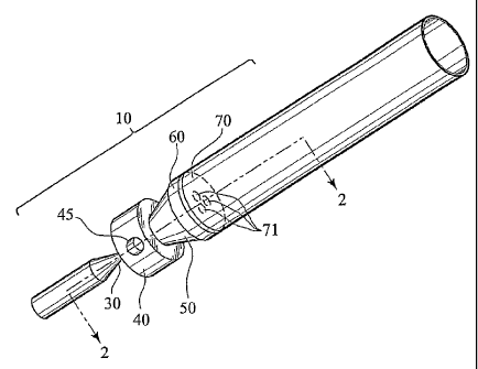
As shown in the figures, a gas burner 10 includes a fuel inlet 20, a venturi,
which
includes a nozzle 30 and an oxygenation chamber 40 with at least one air inlet
45, a mixing
chamber 50, at least one permeable barrier or mixing screen 60 and a flame
holder 70. The
9
CA 02586562 2009-04-07
gas burner 10 produces a stable pre-mixed flame that is generated with lower
fuel mass flow
rates than conventional burners. As a result, a lighter employing the gas
burner 10 of the
present invention may be sized smaller than conventional commercial gas
lighters.
FIG. 1 shows the gas burner 10 of the present invention. The fuel inlet 20
connects a
fuel storage container 15, as shown in FIG. 3, with the nozzle 30. The fuel
inlet 20 provides
a pathway through which gaseous fuel may be fed from the storage container 15,
in which it
is contained, to the gas burner 10. The fuel may be any gaseous fuel known in
the art,
including low molecular weight hydrocarbons such as methane, ethane, propane,
butane, and
acetylene. The nozzle 30 narrows the available volume through which fuel may
travel
through the gas burner 10. The nozzle 30 has an orifice 35, as shown in FIG.
11, that opens
into the oxygenation chamber 40. The inner wall 32 of nozzle 30 may include a
frustoconical section 33, as shown in FIGS. 9-11. Orifice 35 may have a
circular edge or any
other appropriately shaped edge that allows fuel to flow therethrough.
As shown in FIGS. 1 and 2, air inlet(s) 45 are open to ambient and allow air
to be
drawn into the oxygenation chamber 40. At least one air inlet 45 is in flow
communication
with oxygenation chamber 40. In two preferred embodiments, as shown in FIGS. 5-
7 and
FIGS. 24-26, the gas burner 10 may have four or more air inlets 45 conducting
air from
ambient to the oxygenation chamber 40. Additionally, air inlet 45 may have any
appropriate
configuration. For example, air inlet 45 may have a cylindrical sidewall 47
extending
through the sidewall 41 of oxygenation chamber 40, as shown in FIGS. 5-7. As
an
alternative to air inlet 45, an air inlet may be disposed concentrically with
orifice 35 within
proximal wal142 of oxygenation chamber 40. The nozzle 30 and oxygenation
chamber 40
CA 02586562 2009-04-07
cooperate to form a high-efficiency venturi. The pressurized flow of fuel
through the nozzle
30 and orifice 35 into the oxygenation chamber 40 causes a reduction in the
static pressure of
the flow within the oxygenation chamber 40. This reduction of the static
pressure draws air
through the air inlet 45 into the oxygenation chamber 40. In a preferred
embodiment, the
oxygenation chamber 40 is approximately 3-4 mm in length.
The oxygenation chamber 40 is in flow communication with the mixing chamber
50.
The fuel and entrained air flow from the oxygenation chamber into the mixing
chamber 50.
The mixing chamber 50 may have an inner side wall 51 at least a portion 52 of
which is
frustoconical. Alternatively, as shown in FIG. 5, 12 and 13, a mixing ferrule
55 having a
frustoconical inner wall 56 may be included in the gas burner 10 and serve as
the mixing
chamber. In a preferred embodiment, the frustoconical portion 52 of the mixing
chamber 50
is approximately 2-4 mm in length.
As shown in FIG. 2, at least one permeable barrier 60 is in flow communication
with
the mixing chamber 50. The permeable barrier 60 is preferably disposed
downstream from
the mixing chamber 40, as shown in FIGS. 1-4. The presence of the permeable
barrier 60
creates a pressure differential on either side thereof, the higher static
pressure being upstream
of the permeable barrier 60 and the lower pressure being downstream therefrom.
The
pressure differential thereby provides for the formation of recirculation
eddies within the
fuel/air stream to either side of the axis of the mixing chamber. The mixing
of the air and the
fuel occurs on the molecular level and proceeds to near complete mixing before
the fuel/air
mixture leaves the mixing chamber 50.
11
CA 02586562 2009-04-07
The permeable barrier 60 may be formed of a variety of materials and have a
variety
of configurations. The permeable barrier 60 may include a wire mesh formed of
a metallic or
polymeric material, as shown in FIGS. 22-23. For example, in a preferred
embodiment, a
wire mesh formed of nickel wire having a diameter of 0.114mm was included in
the
permeable barrier. Other metals from which the wire mesh may be formed include
brass and
steel. Alternatively, the permeable barrier 60 may be a porous plate formed of
metallic or
ceramic material. A porous plate may have a few large holes, as shown in FIG.
5, 16 and 17,
or many smaller holes, as shown in FIG. 19a and 19b. Regardless of the
configuration and
the materials of construction of the permeable barrier 60, the fuel/air
mixture travels through
the permeable barrier 60. The permeable barrier 60 provides for further mixing
of the
gaseous fuel and air as they pass therethrough. The drop in static pressure
experienced by the
fuel/air mixture as it travels through the permeable barrier 60 serves to
decelerate the mixture
flow so that the flame produced downstream will not lift off from the flame
holder 70, shown
in FIG. 1, 5, 18 and 19.
The pressure differential created by the permeable barrier 60 adversely
affects the rate
of entrainment of air within the burner 10. More particularly, as the pressure
drop caused by
the permeable barrier 60 increases, the flow rate of air entrained by the
venturi decreases,
thereby producing a fuel/air mixture that tends to be more fuel-rich. As a
result, the porosity
of the permeable barrier 60 must be taken into account in selecting a barrier
that provides an
appropriate fuel and air ratio. The goal of mixing the fuel and the air prior
to ignition is to
attain a mixture ratio of fuel to air that approaches a stoichiometric ratio,
or that is slightly
oxygen-rich. The result of a stoichiometrically balanced mixture of fuel and
air is that the
12
CA 02586562 2009-04-07
mixture will proceed to nearly complete combustion upon ignition, thereby
producing a
stable flame without soot or unburned hydrocarbons. Therefore, the porosity or
void fraction
of the permeable barrier 60 should be such that, when combined with a nozzle
30 of a
particular size, the permeable barrier 60 provides a mass flow rate of air
entrained within the
oxygenation chamber 40 that leads to a near stoichiometric ratio between the
gaseous fuel
and air.
The porosity is the percentage of open area present within the permeable
barrier. The
porosity represents the available area through which the fuel/air mixture may
flow from the
mixing chamber 50. In a preferred embodiment, the permeable barrier has a
porosity of
approximately 35% to 40% for a 30 micron diameter nozzle 30, in order to
achieve a fuel to
air ratio that is stoichiometric or slightly oxygen-rich. The preferred
porosity of the
permeable barrier 60 varies with the diameter of the nozzle 30.
The diameter of nozzle 30 also affects the entrainment of air within the
oxygenation
chamber 40. The pressure drop of the fuel flow increases as the diameter of
the nozzle
diameter decreases. In a preferred embodiment, the diameter of the nozzle 30
is within the
range of 30 to 60 microns. However, the present invention contemplates nozzle
diameters
outside of this given range. For nozzles with diameters approaching 50 microns
and greater,
an alternative embodiment of the oxygenation chamber 140 of the present
invention is shown
in FIG. 4. Oxygenation chamber 140 has a spherical side wa11141 and a recessed
portion in
proximal wall 142 in which is disposed an orifice, similar to orifice 35 shown
in FIG. 11,
into which nozzle 130 opens. Air inlet(s) 145 may be disposed within spherical
side wall
141 and/or in proximal wall 142. Oxygenation chamber 140 is in flow
communication with
13
CA 02586562 2009-04-07
both nozzle 130 and mixing chamber 150, which has a frustoconical side wall
151. The
flame holder 170 is in flow communication with the screen 160 and flame tube
180.
As shown in FIG. 1, a flame holder or burner plate 70 is in flow communication
with
the permeable barrier 60. Flame holder 70 has at least one opening 71 therein
through which
the pre-mixed fuel and air stream flows. As with the permeable barrier 60, the
porosity of
the flame holder 70 affects the entrainment rate of air into the oxygenation
chamber 40. The
openings 71 may be circular and may be arranged around the center of the flame
holder 70.
For example, three substantially circular openings 71 may be disposed within
flame holder
70, as shown in FIGS. 1, 5, 18, and 19. The three circular openings 71 may be
disposed
about 120 apart around the center of the flame holder 70. Alternatively, the
flameholder 70
may have non-circular openings. For example, as shown in FIGS. 20 and 21,
flame holder
270 may have three kidney-shaped openings 271 through which the fuel/air
stream flows. It
is contemplated by the present invention that the flame holder 70 has one or
more openings
therein. The flame holder 70 allows the fuel/air mixture to flow therethrough
to the point of
ignition. However, the flame holder 70 prevents the pre-mixed flame produced
by the
combustion of the fuel/air mixture from traveling upstream through the gas
burner 10. In a
preferred embodiment, the flame holder 70 is spaced approximately 1 mm from
the mixing
distal end of the mixing chainber 50.
As shown in FIG. 3, the gas burner 10 may include an ignition source 99
positioned
downstream of the flame holder 70. The ignition source 99 may be any source
known in the
art, such as a piezoelectric element, electrical or flint ignitor.
14
CA 02586562 2009-04-07
As shown in FIGS. 1-5, the gas burner 10 may also include a flame tube 80 or
180 in
which a pre-mixed flame may be contained. The flame tube 80 prevents diffusion
of air to
the pre-mixed flame. The flame tube 80 may be formed of any metallic, ceramic
or
polymeric material that may withstand the temperatures produced by the
combustion process
that occurs in gas burner 10. The flame produced within the gas burner 10 is
disposed
substantially within the flame tube 80.
The gas burner 10 may be housed within a burner housing 90, as shown in FIGS.
3,
and 5. The burner housing 90 may enclose some or all of the fuel inlet 20,
nozzle 30,
oxygenation chamber 40, mixing chamber 50, permeable barrier 60, flame holder
70 and
flame tube 80, as well as a gaseous fuel storage cartridge. Burner housing 90
may optionally
have exhaust port 81 that provides for escape of gases from flame tube 80 when
a smoking
article is inserted into flame tube 80. The burner housing 90 may be formed of
metallic,
ceramic or polymeric material.
As shown in FIGS. 5-19, the gas burner 10 may be provided in an assembly. FIG.
5
shows an exploded view of one embodiment of the gas burner 10. In this
embodiment,
nozzle 30, ferrule 55, permeable barrier 60 and flame holder 70 are disposed
in a burner
housing 90. In this embodiment, burner housing 90 includes oxygenation chamber
40, air
inlets 45 and flame tube 80 having optional exhaust port 81 integrally formed
therein. Shims
59 are disposed between ferrule 55, permeable barrier 60 and flame holder 70.
Shims 59
provide adequate spacing between these components.
The gas burner 10 of the present invention provides for such efficient mixing
of low
molecular weight hydrocarbon fuels, such as butane, with air that the length
of the gas burner
CA 02586562 2009-04-07
may be approximately 50% shorter than the length of a commercially available
butane
burner that produces a pre-mixed flame. As a result, the gas burner 10 of the
present
invention may be disposed in a smoking article in which a smokable material is
burned by an
integral lighter included therein. FIG. 1 a shows the gas burner 10 with a
cigarette 4 disposed
5 in flame tube 80. FIG. lb shows the gas burner 10 with a cigarette 4
disposed in flame tube
80 wherein flame tube 80 has exhaust port 81. Cigarette 4 may include tobacco
5 or any
other aerosol-generating smokable material well known in the art. The size of
such a
smoking article, including the gas bumer 10, may approach the size of a
conventional
cigarette. Optional exhaust port 81 provides for the exhaust of gases from the
flame when a
10 smoking article 4 is inserted into flame tube 80 and no draw of gases is
provided through
smoking article 4.
The foregoing detailed description of the preferred embodiments of the present
invention are given primarily for clearness of understanding and no
unnecessary limitations
are to be understood therefrom for modifications will become obvious to those
skilled in the
art upon reading the disclosure and may be made without departing from the
spirit of the
16