Note: Descriptions are shown in the official language in which they were submitted.
CA 02586924 2007-05-11
WO 2006/071313 PCT/US2005/035245
PATTERNED APPLICATION OF ACTIVATED CARBON INK
Background of the Invention
Odor control additives have been conventionally incorporated into
substrates for a variety of reasons. For instance, absorbent articles may
contain
odor control additives to absorb compounds that result in the production of
malodors contained in absorbed fluids or their degradation products. Examples
of
these compounds include fatty acids, ammonia, amines, sulfur-containing
compounds, ketones and aldehydes. Various types of odor control additives have
been employed for this purpose. For instance, activated carbon has been used
to
reduce a broad spectrum of odors. In spite of its excellent properties as an
adsorbent, the use of activated carbon in disposable absorbent articles has
been
limited by its black color. That is, many consumers associate the
traditionally
black color of activated carbon with a dirty or grimy material.
As such, a need currently exists for odor control substrates that are capable
of achieving reducing odor, and yet also aesthetically pleasing to a consumer.
Summary of the Invention
In accordance with one embodiment of the present invention, a method for
forming an odor control substrate is disclosed. The method comprises forming a
first ink that comprises activated carbon, a binder, and a solvent. The first
ink is
printed onto a surface of the substrate so that it covers from about 25% to
about
95% of the area of the surface. The first ink is dried and has a solids add-on
level
of at least about 2%. The first ink also presents a color (e.g., black) that
is visually
distinguishable from another color presented by the substrate. If desired, a
second ink may also be printed onto the substrate that presents a color that
is
visually distinguishable from the color of the first ink. For example, the
color of the
second ink may be white, yellow, cyan, magenta, red, green, blue, or
combinations
thereof. The first and second inks may be applied in an overlapping and/or non-
overlapping relationship.
In accordance with another embodiment of the present invention, an odor
control substrate is disclosed that is applied with a first ink and a second
ink, the
first ink comprising activated carbon. The first ink covers from about 30% to
about
90% of the area of a surface of the substrate and is present at a solids add-
on
level of at least about 2%. The first ink presents a color that is visually
1
CA 02586924 2007-05-11
WO 2006/071313 PCT/US2005/035245
distinguishable from the color of the second ink.
In accordance with still another embodiment of the present invention, a
pouch for individually wrapping a feminine care absorbent article is
disclosed. The
pouch comprises a wrapper having an inner surface. The inner surface is
applied
with a first ink that comprises activated carbon. The first ink covers from
about
25% to about 95% of the area of the inner surface. The first ink presents a
color
that is visually distinguishable from another color presented by the wrapper.
Other features and aspects of the present invention are described in more
detail below.
Brief Description of the Drawings
A full and enabling disclosure of the present invention, including the best
mode thereof, directed to one of ordinary skill in the art, is set forth more
particularly in the remainder of the specification, which makes reference to
the
appended figures in which:
Fig. I illustrates an odor control substrate having overlapping color patterns
in accordance with one embodiment of the present invention, in which Fig. 1A
depicts a colored ink printed on top of an activated carbon ink and in which
Fig. 1 B
depicts an activated carbon ink printed on top of a colored ink;
Fig. 2 illustrates an odor control substrate having non-overlapping color
patterns in accordance with another embodiment of the present invention;
Fig. 3 is a perspective view of one embodiment of an individually wrapped
absorbent article package of the present invention;
Fig. 4 is a perspective view of the package of Fig. 1 shown in its opened
state; and
Fig. 5 graphically depicts the results of the Example 1, in which the odor
adsorption of ethyl mercaptan is plotted versus coverage area for various
coating
weights.
Repeat use of reference characters in the present specification and
drawings is intended to represent same or analogous features or elements of
the
invention.
Detailed Description of Representative Embodiments
Definitions
As used herein the term "nonwoven fabric or web" refers to a web having a
2
CA 02586924 2007-05-11
WO 2006/071313 PCT/US2005/035245
structure of individual fibers or threads which are interlaid, but not in an
identifiable
manner as in a knitted fabric. Nonwoven fabrics or webs have been formed from
many processes such as for example, meltblowing processes, spunbonding
processes, bonded carded web processes, etc.
As used herein, the term "meltblown web" generally refers to a nonwoven
web that is formed by a process in which a molten thermoplastic material is
extruded through a plurality of fine, usually circular, die capillaries as
molten fibers
into converging high velocity gas (e.g. air) streams that attenuate the fibers
of
molten thermoplastic material to reduce their diameter, which may be to
microfiber
0 diameter. Thereafter, the meltblown fibers are carried by the high velocity
gas
stream and are deposited on a collecting surface to form a web of randomly
disbursed meltblown fibers. Such a process is disclosed, for example, in U.S.
Pat.
No. 3,849,241 to Butin, et al., which is incorporated herein in its entirety
by
reference thereto for all purposes. Generally speaking, meltblown fibers may
be
5 microfibers that are substantially continuous or discontinuous, generally
smaller
than 10 microns in diameter, and generally tacky when deposited onto a
collecting
surface.
As used herein, the term "spunbond web" generally refers to a web
containing small diameter substantially continuous fibers. The fibers are
formed
'.0 by extruding a molten thermoplastic material from a plurality of fine,
usually
circular, capillaries of a spinnerette with the diameter of the extruded
fibers then
being rapidly reduced as by, for example, eductive drawing and/or other well-
known spunbonding mechanisms. The production of spunbond webs is described
and illustrated, for example, in U.S. Patent Nos. 4,340,563 to Appel, et al.,
?5 3,692,618 to Dorschner, et al., 3,802,817 to Matsuki, et al., 3,338,992 to
Kinney,
3,341,394 to Kinney, 3,502,763 to Hartman, 3,502,538 to Levy, 3,542,615 to
Dobo, et al., and 5,382,400 to Pike, et al., which are incorporated herein in
their
entirety by reference thereto for all purposes. Spunbond fibers are generally
not
tacky when they are deposited onto a collecting surface. Spunbond fibers may
30 sometimes have diameters less than about 40 microns, and are often between
about 5 to about 20 microns.
As used herein, the term "coform" generally refers to composite materials
comprising a mixture or stabilized matrix of thermoplastic fibers and a second
non-
3
CA 02586924 2007-05-11
WO 2006/071313 PCT/US2005/035245
thermoplastic material. As an example, coform materials may be made by a
process in which at least one meltblown die head is arranged near a chute
through
which other materials are added to the web while it is forming. Such other
materials may include, but are not limited to, fibrous organic materials such
as
woody or non-woody pulp such as cotton, rayon, recycled paper, pulp fluff and
also superabsorbent particles, inorganic and/or organic absorbent materials,
treated polymeric staple fibers and so forth. Some examples of such coform
materials are disclosed in U.S. Patent Nos. 4,100,324 to Anderson, et al.;
5,284,703 to Everhart, et al.; and 5,350,624 to Georger, et al.; which are
incorporated herein in their entirety by reference thereto for all purposes.
As used herein, the term "multicomponent fibers" generally refers to fibers
that have been formed from at least two polymer components. Such fibers are
typically extruded from separate extruders, but spun together to form one
fiber.
The polymers of the respective components are typically different, but may
also
include separate components of similar or identical polymeric materials. The
individual components are typically arranged in substantially constantly
positioned
distinct zones across the cross-section of the fiber and extend substantially
along
the entire length of the fiber. The configuration of such fibers may be, for
example, a side-by-side arrangement, a pie arrangement, or any other
arrangement. Multicomponent fibers and methods of making the same are taught
in U.S. Patent Nos. 5,108,820 to Kaneko, et al., 4,795,668 to Kruege, et al.,
5,382,400 to Pike, et al., 5,336,552 to Strack, et al., and 6,200,669 to
Marmon, et
al., which are incorporated herein in their entirety by reference thereto for
all
purposes. The fibers and individual components containing the same may also
have various irregular shapes such as those described in U.S. Patent. Nos.
5,277,976 to Hogle, et al., 5,162,074 to Hills, 5,466,410 to Hills, 5,069,970
to
Largman, et al., and 5,057,368 to Largman, et al., which are incorporated
herein in
their entirety by reference thereto for all purposes.
As used herein, the term "elastomeric" and "elastic" and refers to a material
that, upon application of a stretching force, is stretchable in at least one
direction
(such as the CD direction), and which upon release of the stretching force,
contracts/returns to approximately its original dimension. For example, a
stretched
material may have a stretched length that is at least 50% greater than its
relaxed
4
CA 02586924 2007-05-11
WO 2006/071313 PCT/US2005/035245
unstretched length, and which will recover to within at least 50% of its
stretched
length upon release of the stretching force. A hypothetical example would be a
one
(1) inch sample of a material that is stretchable to at least 1.50 inches and
which,
upon release of the stretching force, will recover to a length of not more
than 1.25
inches. Desirably, such elastomeric sheet contracts or recovers at least 50%,
and
even more desirably, at least 80% of the stretch length in the cross machine
direction.
As used herein, the term "breathable" means pervious to water vapor and
gases, but impermeable to liquid water. For instance, "breathable barriers"
and
0 "breathable films" allow water vapor to pass therethrough, but are
substantially
impervious to liquid water. The "breathability" of a material is measured in
terms
of water vapor transmission rate (WVTR), with higher values representing a
more
vapor-pervious material and lower values representing a less vapor-pervious
material. Typically, the'breathable" materials have a water vapor transmission
rate (WVTR) of from about 500 to about 20,000 grams per square meter per 24
hours (g/m2/24 hours), in some embodiments from about 1,000 to about 15,000
g/m2/24 hours, and in some embodiments, from about 1,500 to about 14,000
g/m2/24 hours.
As used herein, an "absorbent article" refers to any article capable of
?0 absorbing water or other fluids. Examples of some absorbent articles
include, but
are not limited to, personal care absorbent articles, such as diapers,
training pants,
absorbent underpants, adult incontinence products, feminine hygiene products
(e.g., sanitary napkins), swim wear, baby wipes, and so forth; medical
absorbent
articles, such as garments, fenestration materials, underpads, bandages,
?5 absorbent drapes, and medical wipes; food service wipers; clothing
articles; and
so forth. Materials and processes suitable for forming such absorbent articles
are
well known to those skilled in the art.
Detailed Description
Reference now will be made in detail to various embodiments of the
30 invention, one or more examples of which are set forth below. Each example
is
provided by way of explanation, not limitation of the invention. In fact, it
will be
apparent to those skilled in the art that various modifications and variations
may
be made in the present invention without departing from the scope or spirit of
the
5
CA 02586924 2007-05-11
WO 2006/071313 PCT/US2005/035245
invention. For instance, features illustrated or described as part of one
embodiment, may be used on another embodiment to yield a still further
embodiment. Thus, it is intended that the present invention cover such
modifications and variations.
In general, the present invention is directed to an odor control substrate
that
is applied with an activated carbon ink. The activated carbon ink is applied
in a
pattern that covers from about 25% to about 95% of the surface area of the
substrate. Although not covering the entire surface, the present inventors
have
discovered that the activated carbon ink is still capable of providing good
odor
0 reduction qualities to the substrate. To further enhance the aesthetic
appeal of
the odor control substrate to a consumer, one or more colored inks may also be
applied the substrate in a pattern that may or may not overlap with the
activated
carbon ink pattern. The colored ink(s) may contrast well with the activated
carbon
ink to provide an overall design that is more aesthetically than otherwise
would be
5 provided by a uniform coating of activated carbon ink.
A. Substrates
Any of variety of substrates may be applied with an activated carbon ink in
accordance with the present invention. For example, nonwoven webs, woven
fabrics, knit fabrics, films, and so forth, may be employed. In most
embodiments,
'0 the substrate contains at least one nonwoven web. When utilized, the
nonwoven
web may include, but not limited to, spunbond webs, meltblown webs, bonded
carded webs, air-laid webs, coform webs, hydraulically entangled webs, and so
forth. Nonwoven webs may be formed by a variety of different materials. For
instance, suitable polymers for forming nonwoven webs may include polyolefins,
?5 polyamides, polyesters, polycarbonates, polystyrenes, thermoplastic
elastomers,
fluoropolymers, vinyl polymers, and blends and copolymers thereof. Suitable
polyolefins include, but are not limited to, polyethylene, polypropylene,
polybutylene, and so forth; suitable polyamides include, but are not limited
to,
nylon 6, nylon 6/6, nylon 10, nylon 12 and so forth; and suitable polyesters
include,
30 but are not limited to, polyethylene terephthalate, polybutylene
terephthalate,
polytrimethyl terephthalate, polylactic acid, and so forth. Particularly
suitable
polymers for use in the present invention are polyolefins including
polyethylene, for
example, linear low density polyethylene, low density polyethylene, medium
6
CA 02586924 2007-05-11
WO 2006/071313 PCT/US2005/035245
density polyethylene, and high density polyethylene; polypropylene;
polybutylene;
as well as copolymers and blends thereof.
The fibers used to form the nonwoven web may be in the form of
substantially continuous fibers, staple fibers, and so forth. Substantially
continuous fibers, for example, may be produced by known nonwoven extrusion
processes, such as, for example, known solvent spinning or melt-spinning
processes. In one embodiment, the nonwoven web contains substantially
continuous melt-spun fibers formed by a spunbond process. The spunbond fibers
may be formed from any melt-spinnable polymer, co-polymers or blends thereof.
0 The denier of the fibers used to form the nonwoven web may also vary. For
instance, in one particular embodiment, the denier of polyolefin fibers used
to form
the nonwoven web is less than about 6, in some embodiments less than about 3,
and in some embodiments, from about 1 to about 3. In one particular embodiment
of the present invention, multicomponent (e.g., bicomponent) fibers are
utilized.
5 For example, suitable configurations for the multicomponent fibers include
side-by-
side configurations and sheath-core configurations, and suitable sheath-core
configurations include eccentric sheath-core and concentric sheath-core
configurations. In some embodiments, as is well known in the art, the polymers
used to form the multicomponent fibers have sufficiently different melting
points to
'.0 form different crystallization and/or solidification properties. The
multicomponent
fibers may have from about 20% to about 80%, and in some embodiments, from
about 40% to about 60% by weight of the low melting polymer. Further, the
multicomponent fibers may have from about 80% to about 20%, and in some
embodiments, from about 60% to about 40%, by weight of the high melting
?5 polymer.
As stated above, a film may also be utilized to form the substrate. To form
a film, a variety of materials may be utilized. For instance, some suitable
thermoplastic polymers used in the fabrication of films may include, but are
not
limited to, polyolefins (e.g., polyethylene, polypropylene, etc.), including
30 homopolymers, copolymers, terpolymers and blends thereof; ethylene vinyl
acetate; ethylene ethyl acrylate; ethylene acrylic acid; ethylene methyl
acrylate;
ethylene normal butyl acrylate; polyurethane; poly(ether-ester); poly(amid-
ether)
block copolymers; and so forth.
7
CA 02586924 2007-05-11
WO 2006/071313 PCT/US2005/035245
In one particular embodiment, the film may be made a liquid-impermeable
plastic film, such as a polyethylene and polypropylene film. Generally, such
plastic
films are impermeable to gases and water vapor, as well as liquids. In
addition,
the film may be impermeable to liquids, but permeable to gases and water vapor
(i.e., "breathable"). Such breathable films are useful in a variety of
articles, such
as in an outer cover of an absorbent article to permit vapors to escape from
the
absorbent core, but prevent liquid exudates from passing therethrough. The
breathable film may be microporous or monolithic. In microporous films, the
micropores form what is often referred to as tortuous pathways through the
film.
0 Liquid contacting one side of the film does not have a direct passage
through the
film. Instead, a network of microporous channels in the film prevents liquids
from
passing, but allows gases and water vapor to pass. Microporous films may be
formed from a polymer and a filler (e.g., calcium carbonate). Fillers are
particulates or other forms of material that may be added to the film polymer
5 extrusion blend and that will not chemically interfere with the extruded
film, but
which may be uniformly dispersed throughout the film. Generally, on a dry
weight
basis, based on the total weight of the film, the film includes from about 30%
to
about 90% by weight of a polymer. In some embodiments, the film includes from
about 30% to about 90% by weight of a filler. Examples of such films are
!0 described in U.S. Patent Nos. 5,843,057 to McCormack; 5,855,999 to
McCormack; 5,932,497 to Morman, et al.; 5,997,981 to McCormack et al.;
6,002,064 to Kobylivker, et al.; 6,015,764 to McCormack, et al.; 6,037,281 to
Mathis, et al.; 6,111,163 to McCormack, et al.; and 6,461,457 to Taylor, et
al.,
which are incorporated herein in their entirety by reference thereto for all
?5 purposes.
The films are generally made breathable by stretching the filled films to
create the microporous passageways as the polymer breaks away from the
calcium carbonate during stretching. For example, the breathable material
contains a stretch-thinned film that includes at least two basic components,
i.e., a
30 polyolefin polymer and filler. These components are mixed together, heated,
and
then extruded into a film layer using any one of a variety of film-producing
processes known to those of ordinary skill in the film processing art. Such
film-
making processes include, for example, cast embossed, chill and flat cast, and
8
CA 02586924 2007-05-11
WO 2006/071313 PCT/US2005/035245
blown film processes.
Another type of breathable film is a monolithic film that is a nonporous,
continuous film, which because of its molecular structure, is capable of
forming a
Iiquid-impermeable, vapor-permeable barrier. Among the various polymeric films
that fall into this type include films made from a sufficient amount of
poly(vinyl
alcohol), polyvinyl acetate, ethylene vinyl alcohol, polyurethane, ethylene
methyl
acrylate, and ethylene methyl acrylic acid to make them breathable. Without
intending to be held to a particular mechanism of operation, it is believed
that films
made from such polymers solubilize water molecules and allow transportation of
0 those molecules from one surface of the film to the other. Accordingly,
these films
may be sufficiently continuous, i.e., nonporous, to make them substantially
liquid-
impermeable, but still allow for vapor permeability.
Breathable films, such as described above, may constitute the entire
breathable material, or may be part of a multilayer film. Multilayer films may
be
prepared by cast or blown film coextrusion of the layers, by extrusion
coating, or
by any conventional layering process. Further, other breathable materials that
may be suitable for use in the present invention are described in U.S. Patent
Nos.
4,341,216 to Obenour; 4,758,239 to Yeo, et al.; 5,628,737 to Dobrin, et al.;
5,836,932 to Buell; 6,114,024 to Forte; 6,153,209 to Vega, et al.; 6,198,018
to
?0 Curro; 6,203,810 to Alemany, et al.; and 6,245,401 to Ying, et al., which
are
incorporated herein in their entirety by reference thereto for all purposes.
If desired, the breathable film may also be bonded to a nonwoven web,
knitted fabric, and/or woven fabric using well-known techniques. For instance,
suitable techniques for bonding a film to a nonwoven web are described in U.S.
?5 Patent Nos. 5,843,057 to McCormack; 5,855,999 to McCormack; 6,002,064 to
Kobylivker, et al.; 6,037,281 to Mathis, et al.; and WO 99/12734, which are
incorporated herein in their entirety by reference thereto for all purposes.
For
example, a breathable film/nonwoven laminate material may be formed from a
nonwoven layer and a breathable film layer. The layers may be arranged so that
30 the breathable film layer is attached to the nonwoven layer. In one
particular
embodiment, the breathable material is formed from a nonwoven fabric (e.g.,
polypropylene spunbond web) laminated to a breathable film.
The substrate may also contain an elastomeric polymer, such as
9
CA 02586924 2007-05-11
WO 2006/071313 PCT/US2005/035245
elastomeric polyesters, elastomeric polyurethanes, elastomeric polyamides,
elastomeric polyolefins, elastomeric copolymers, and so forth. Examples of
elastomeric copolymers include block copolymers having the general formula A-B-
A' or A-B, wherein A and A' are each a thermoplastic polymer endblock that
contains a styrenic moiety and B is an elastomeric polymer midblock, such as a
conjugated diene or a lower alkene polymer. Such copolymers may include, for
instance, styrene-isoprene-styrene (S-1-S), styrene-butadiene-styrene (S-B-S),
styrene-ethylene-butylene-styrene (S-EB-S), styrene-isoprene (S-I), styrene-
butadiene (S-B), and so forth. Commercially available A-B-A' and A-B-A-B
copolymers include several different S-EB-S formulations from Kraton Polymers
of
Houston, Texas under the trade designation KRATONO. KRATONO block
copolymers are available in several different formulations, a number of which
are
identified in U.S. Patent Nos. 4,663,220, 4,323,534, 4,834,738, 5,093,422 and
5,304,599, which are hereby incorporated in their entirety by reference
thereto for
5 all purposes. Other commercially available block copolymers include the S-EP-
S
elastomeric copolymers available from Kuraray Company, Ltd. of Okayama,
Japan, under the trade designation SEPTONO. Still other suitable copolymers
include the S-I-S and S-B-S elastomeric copolymers available from Dexco
Polymers of Houston, Texas under the trade designation VECTOR . Also
10 suitable are polymers composed of an A-B-A-B tetrablock copolymer, such as
discussed in U.S. Patent No. 5,332,613 to Taylor, et al., which is
incorporated
herein in its entirety by reference thereto for all purposes. An example of
such a
tetrablock copolymer is a styrene-poly(ethylene-propylene)-styrene-
poly(ethylene-
propylene) ("S-EP-S-EP") block copolymer.
5 Examples of elastomeric polyolefins include ultra-low density elastomeric
polypropylenes and polyethylenes, such as those produced by "single-site" or
"metallocene" catalysis methods. Such elastomeric olefin polymers are
commercially available from ExxonMobil Chemical Co. of Houston, Texas under
the trade designations ACHIEVEO (propylene-based), EXACTO (ethylene-based),
D and EXCEEDO (ethylene-based). Elastomeric olefin polymers are also
commercially available from DuPont Dow Elastomers, LLC (a joint venture
between DuPont and the Dow Chemical Co.) under the trade designation
ENGAGEO (ethylene-based) and from Dow Chemical Co. of Midland, Michigan
CA 02586924 2007-05-11
WO 2006/071313 PCT/US2005/035245
under the name AFFINITY (ethylene-based). Examples of such polymers are
also described in U.S. Patent Nos. 5,278,272 and 5,272,236 to Lai, et al.,
which
are incorporated herein in their entirety by reference thereto for all
purposes. Also
useful are certain elastomeric polypropylenes, such as described in U.S.
Patent
Nos. 5,539,056 to Yang, et al. and 5,596,052 to Resconi, et al., which are
incorporated herein in their entirety by reference thereto for all purposes.
If desired, biends of two or more polymers may also be utilized. For
example, a blend of a high performance elastomer and a lower performance
elastomer may be utilized. A high performance elastomer is generally an
elastomer having a low level of hysteresis, such as less than about 75%, and
in
some embodiments, less than about 60%. Likewise, a low performance elastomer
is generally an elastomer having a high level of hysteresis, such as greater
than
about 75%. Particularly suitable high performance elastomers may include
styrenic-based block copolymers, such as described above and commercially
available from Kraton Polymers under the trade designation KRATON and from
Dexco Polymers under the trade designation VECTOR . Likewise, particularly
suitable low performance elastomers include elastomeric polyolefins, such as
metaiiocene-catalyzed polyolefins (e.g., single site metallocene-catalyzed
linear
low density polyethylene) commercially available from Dow Chemical Co. under
'0 the trade designation AFFINITY . In some embodiments, the high performance
elastomer may constitute from about 25 wt.% to about 90 wt.% of the blend, and
the low performance elastomer may likewise constitute from about 10 wt.% to
about 75 wt.% of the blend. Further examples of such a high performance/low
performance elastomer blend are described in U.S. Patent No. 6,794,024 to
5 Walton, et al., which is incorporated herein in its entirety by reference
thereto for
all purposes.
B. Activated Carbon Inks
Regardless of the particular substrate selected, an activated carbon ink is
applied to the substrate for reducing odor. When applied in accordance with
the
0 present invention, the ink is also durable and present in an aesthetically
pleasing
pattern on the substrate. Generally speaking, activated carbon may be derived
from a variety of sources, such as from sawdust, wood, charcoal, peat,
lignite,
bituminous coal, coconut shells, etc. Some suitable forms of activated carbon
and
11
CA 02586924 2007-05-11
WO 2006/071313 PCT/US2005/035245
techniques for formation thereof are described in U.S. Patent Nos. 5,693,385
to
Parks; 5,834,114 to Economy, et al.; 6,517,906 to Economy, et al.; 6,573,212
to
McCrae, et al., as well as U.S. Patent Application Publication Nos.
2002/0141961
to Falat, et al. and 2004/0166248 to Hu, et al., all of which are incorporated
herein
in their entirety by reference thereto for all purposes. The concentration of
activated carbon in the ink (prior to drying) is generally tailored to
facilitate odor
control without adversely affecting other properties of the substrate, such as
flexibility, absorbency, etc. For instance, activated carbon is typically
present in
the ink in an amount from about 1 wt.% to about 50 wt.%, in some embodiments
0 from about 5 wt.% to about 25 wt.%, and in some embodiments, from about 10
wt.% to about 20 wt.%.
The activated carbon ink also generally contains a binder for increasing the
durability of the activated carbon when applied to a substrate, even when
present
at high levels. The binder may also serve as an adhesive for bonding one
5 substrate to another substrate. Generally speaking, any of a variety of
binders
may be used in the activated carbon ink of the present invention. Suitable
binders
may include, for instance, those that become insoluble in water upon
crosslinking.
Crosslinking may be achieved in a variety of ways, including by reaction of
the
binder with a polyfunctional crosslinking agent. Examples of such crosslinking
agents include, but are not limited to, dimethylol urea melamine-formaldehyde,
urea-formaldehyde, polyamide epichlorohydrin, etc.
In some embodiments, a polymer latex may be employed as the binder.
The polymer suitable for use in the lattices typically has a glass transition
temperature of about 30 C or less so that the flexibility of the resulting
substrate is
not substantially restricted. Moreover, the polymer also typically has a glass
transition temperature of about -25 C or more to minimize the tackiness of the
polymer latex. For instance, in some embodiments, the polymer has a glass
transition temperature from about -15 C to about 15 C, and in some
embodiments, from about -10 C to about 0 C. For instance, some suitable
0 polymer lattices that may be utilized in the present invention may be based
on
polymers such as, but are not limited to, styrene-butadiene copolymers,
polyvinyl
acetate homopolymers, vinyl-acetate ethylene copolymers, vinyl-acetate acrylic
copolymers, ethylene-vinyl chloride copolymers, ethylene-vinyl chloride-vinyl
12
CA 02586924 2007-05-11
WO 2006/071313 PCT/US2005/035245
acetate terpolymers, acrylic polyvinyl chloride polymers, acrylic polymers,
nitrile
polymers, and any other suitable anionic polymer latex polymers known in the
art.
The charge of the polymer lattices described above may be readily varied, as
is
well known in the art, by utilizing a stabilizing agent having the desired
charge
during preparation of the polymer latex. For instance, specific techniques for
an
activated carbon/polymer latex system are described in more detail in U.S.
Patent
No. 6,573,212 to McCrae, et al. Commercially available activated
carbon/polymer
latex systems that may be used in the present invention include Nuchar PMA,
DPX-8433-68A, and DPX-8433-68B, all of which are available from
0 MeadWestvaco Corp of Covington, Virginia.
Although polymer lattices may be effectively used as binders in the present
invention, such compounds sometimes result in a reduction in drapability and
an
increase in residual odor. Thus, water-soluble organic polymers may also be
employed as binders to alleviate such concerns. Another benefit of the water-
5 soluble binder of the present invention is that it may facilitate the
controlled
release of the activated carbon ink from the substrate in an aqueous
environment.
Specifically, upon contacting an aqueous solution, the water-soluble binder
dissolves and loses some of its binding qualities, thereby allowing other
components of the activated carbon ink to be released from the substrate. This
:0 may be useful in various applications, such as for hard-surface wipers in
which it is
desired for the activated carbon ink to be released into the wiped environment
for
sustained odor control.
One class of water-soluble organic polymers found to be suitable in the
present invention is polysaccharides and derivatives thereof. Polysaccharides
are
!5 polymers containing repeated carbohydrate units, which may be cationic,
anionic,
nonionic, and/or amphoteric. In one particular embodiment, the polysaccharide
is
a nonionic, cationic, anionic, and/or amphoteric cellulosic ether. Suitable
nonionic
cellulosic ethers may include, but are not limited to, alkyl cellulose ethers,
such as
methyl cellulose and ethyl cellulose; hydroxyalkyl cellulose ethers, such as
SO hydroxyethyl cellulose, hydroxypropyl cellulose, hydroxypropyl hydroxybutyl
cellulose, hydroxyethyl hydroxypropyl cellulose, hydroxyethyl hydroxybutyl
cellulose and hydroxyethyl hydroxypropyl hydroxybutyl cellulose; alkyl
hydroxyalkyl
cellulose ethers, such as methyl hydroxyethyl cellulose, methyl hydroxypropyl
13
CA 02586924 2007-05-11
WO 2006/071313 PCT/US2005/035245
cellulose, ethyl hydroxyethyl cellulose, ethyl hydroxypropyl cellulose, methyl
ethyl
hydroxyethyl cellulose and methyl ethyl hydroxypropyl cellulose; and so forth.
Suitable cellulosic ethers may include, for instance, those available from
Akzo Nobel of Covington, Virginia under the name "BERMOCOLL." Still other
suitable cellulosic ethers are those available from Shin-Etsu Chemical Co.,
Ltd. of
Tokyo, Japan under the name "METOLOSE", including METOLOSE Type SM
(methycellulose), METOLOSE Type SH (hydroxypropylmethyl cellulose), and
METOLOSE Type SE (hydroxyethylmethyl cellulose). One particular example of a
suitable nonionic cellulosic ether is ethyl hydroxyethyl cellulose having a
degree of
0 ethyl substitution (DS) of 0.8 to 1.3 and a molar substitution (MS) of
hydroxyethyl
of 1.9 to 2.9. The degree of ethyl substitution represents the average number
of
hydroxyl groups present on each anhydroglucose unit that have been reacted,
which may vary between 0 and 3. The molar substitution represents the average
number of hydroxethyl groups that have reacted with each anhydroglucose unit.
5 One such cellulosic ether is BERMOCOLL E 230FQ, which is an ethyl
hydroxyethyl cellulose commercially available from Akzo Nobel. Other suitable
cellulosic ethers are also available from Hercules, Inc. of Wilmington,
Delaware
under the name "CULMINAL."
The total concentration of the binders may generally vary depending on the
:0 desired properties of the resulting substrate. For instance, high total
binder
concentrations may provide better physical properties for the coated
substrate, but
may likewise have an adverse affect on other properties, such as the
absorptive
capacity or extensibility of the substrate to which it is applied. Conversely,
low
total binder concentrations may not provide the desired degree of durability.
Thus,
'5 in most embodiments, the total amount of binder employed in the activated
carbon
ink (prior to drying) is from about 0.01 wt.% to about 30 wt.%, in some
embodiments from about 0.1 wt.% to about 20 wt.%, and in some embodiments,
from about 1 wt.% to about 15 wt.%.
Besides the above-mentioned components, a masking agent may also be
30 employed in the activated carbon ink to further alter the aesthetic
properties of the
substrate. That is, the masking agent may enhance opacity and/or alter the
color
to the ink. To provide optimum masking effects, the size of the particles is
desirably less than the size of any activated carbon particles employed. For
14
CA 02586924 2007-05-11
WO 2006/071313 PCT/US2005/035245
example, the masking particles may have a size less than about 100
micrometers,
in some embodiments less than about 50 micrometers, and in some
embodiments, less than about 25 micrometers. For example, activated carbon
particles may sometimes have a particle size of approximately 35 micrometers.
In
such cases, the size of the masking particles is typically less than 35
micrometers,
and preferably much smaller, such as less than about 10 micrometers. Likewise,
the particles may be porous. Without intending to be limited by theory, it is
believed that porous particles may provide a passage for odorous compounds to
better contact the odor adsorbent. For example, the particles may have
0 pores/channels with a mean diameter of greater than about 5 angstroms, in
some
embodiments greater than about 20 angstroms, and in some embodiments,
greater than about 50 angstroms. The surface area of such particles may also
be
greater than about 15 square meters per gram, in some embodiments greater than
about 25 square meters per gram, and in some embodiments, greater than about
5 50 square meters per gram. Surface area may be determined by the physical
gas
adsorption (B.E.T.) method of Bruanauer, Emmet, and Teller, Journal of
American
Chemical Society, Vol. 60, 1938, p. 309, with nitrogen as the adsorption gas.
In one particular embodiment, porous carbonate particles (e.g., calcium
carbonate) are used to alter the black color normally associated with
activated
:0 carbon. Such a color change may be more aesthetically pleasing to a user,
particularly when the coating is employed on substrates designed for
consumer/personal use. Suitable white calcium carbonate particles are
commercially available from Omya, Inc. of Proctor, Vermont. Still other
suitable
particles include, but are not limited to, silicates, such as calcium
silicate, alumina
'5 silicates (e.g., mica powder, clay, etc.), magnesium silicates (e.g.,
talc), quartzite,
calcium silicate fluorite, etc.; alumina; silica; and so forth. The
concentration of the
particles may generally vary depending on the nature of the particles, and the
desired extent of odor control and color alteration. For instance, the
particles may
be present in the ink (prior to drying) in an amount from about 0.01 wt.% to
about
30 30 wt.%, in some embodiments from about 0.1 wt.% to about 20 wt.%, and in
some embodiments, from about 1 wt.% to about 15 wt.%.
Other compounds, such as surfactants, electrolytic salts, pH adjusters, etc.,
may also be included in the activated carbon ink of the present invention.
CA 02586924 2007-05-11
WO 2006/071313 PCT/US2005/035245
Although not required, such additional components typically constitute less
than
about 5 wt.%, in some embodiments less than about 2 wt.%, and in some
embodiments, from about 0.001 wt.% to about 1 wt.% of the activated carbon ink
(prior to drying). For example, as is well known in the art, an electrolytic
salt may
be employed to control the gelation temperature of a water-soluble binder.
Suitable electrolytic salts may include, but are not limited to, alkali
halides or
sulfates, such as sodium chloride, potassium chloride, etc.; alkaline halides
or
sulfates, such as calcium chloride, magnesium chloride, etc., and so forth.
To form the activated carbon ink, its components are first typically dissolved
or dispersed in a solvent. For example, one or more of the above-mentioned
components may be mixed with a solvent, either sequentially or simultaneously,
to
form an ink formulation that may be easily applied to a substrate. Any solvent
capable of dispersing or dissolving the components is suitable, for example
water;
alcohols such as ethanol or methanol; dimethylformamide; dimethyl sulfoxide;
5 hydrocarbons such as pentane, butane, heptane, hexane, toluene and xylene;
ethers such as diethyl ether and tetrahydrofuran; ketones and aldehydes such
as
acetone and methyl ethyl ketone; acids such as acetic acid and formic acid;
and
halogenated solvents such as dichloromethane and carbon tetrachloride; as well
as mixtures thereof. The concentration of solvent in the ink formulation is
0 generally high enough to allow easy application, handling, etc. If the
amount of
solvent is too large, however, the amount of activated carbon deposited on the
substrate might be too low to provide the desired odor reduction. Although the
actual concentration of solvent employed will generally depend on the type of
activated carbon and the substrate on which it is applied, it is nonetheless
typically
5 present in an amount from about 40 wt.% to about 99 wt.%, in some
embodiments
from about 50 wt.% to about 95 wt.%, and in some embodiments, from about 60
wt.% to about 90 wt.% of the ink (prior to drying).
The solids content and/or viscosity of the ink may be varied to achieve the
extent of odor reduction desired. For example, the ink may have a solids
content
D of from about 5% to about 90%, in some embodiments from about 10% to about
80%, and in some embodiments, from about 20% to about 70%. By varying the
solids content of the ink, the presence of the activated carbon and other
components in the activated carbon ink may be controlled. For example, to form
16
CA 02586924 2007-05-11
WO 2006/071313 PCT/US2005/035245
an activated carbon ink with a higher level of activated carbon, the ink may
be
provided with a relatively high solids content so that a greater percentage of
activated carbon is incorporated into the activated carbon ink during the
application process. Generally, the viscosity is less than about 2 x 10⁶
centipoise,
in some embodiments less than about 2 x 10⁵ centipoise, in some embodiments
less than about 2 x 10⁴ centipoise, and in some embodiments, less than about 2
x
103 centipoise, such as measured with a Brookfield viscometer, type DV-I or LV-
IV, at 60 rpm and 20 C. If desired, thickeners or other viscosity modifiers
may be
employed in the ink to increase or decrease viscosity.
C. Ink Application
The activated carbon ink is applied to the substrate in a pattern that
presents a stark and highly visible contrast against a different color, such
as the
color of the background. Thus, instead of being hidden within the substrate,
the
activated carbon ink is used to change the overall appearance of the
substrate.
5 For example, the activated carbon ink may have a dark color (e.g., black)
and
applied against a contrasting light background. Alternatively, a differently
colored
foreground may contrast with a dark background provided by the activated
carbon
ink. The relative degree of contrast between the odor control ink and the
other
color may be measured through a gray-level difference value. In a particular
0 embodiment, the contrast may have a gray level value of about 45 on a scale
of 0
to about 255, where 0 represents "black" and 255 represents "white." The
analysis
method may be made with a Quantimet 600 Image Analysis System (Leica, Inc.,
Cambridge, UK). This system's software (QWIN Version 1.06A) enables a
program to be used in the Quantimet User Interactive Programming System
5 (QUIPS) to make the gray-level determinations. A control or "blank" white-
level
may be set using undeveloped Polaroid photographic film. An 8-bit gray-level
scale may then be used (0-255) and the program allowed the light level to be
set
by using the photographic film as the standard. A region containing the other
color
(e.g., background or foreground) may then be measured for its gray-level
value,
3 followed by the same measurement of the activate carbon ink. The routine may
be programmed to automatically calculate the gray-level value of the activated
carbon ink. The difference in gray-level value between the activated carbon
ink
and the other color may be about 45 or greater on a scale of 0-255, where 0
17
CA 02586924 2007-05-11
WO 2006/071313 PCT/US2005/035245
represents "black" and 255 represents "white."
The particular type or style of activated carbon ink pattern is not a limiting
factor of the invention, and may include, for example, any arrangement of
stripes,
bands, dots, or other geometric shape. The pattern may include indicia (e.g.,
trademarks, text, and logos), floral designs, abstract designs, any
configuration of
artwork, etc. The pattern may be targeted for a specific class of consumers.
For
example, in the case of diapers or training pants, the pattern may be in the
form of
cartoon characters, and so forth. It should be appreciated that the "pattern"
may
take on virtually any desired appearance.
0 Nevertheless, the activated carbon ink usually covers from about 25% to
about 95% of the surface area of the substrate, in some embodiments from about
30% to about 90% of the surface area of the substrate, and in some
embodiments, from about 30% to about 50% of the surface area of one or more
surfaces of the substrate. Not only does such a patterned application have
5 improved aesthetic appeal in comparison to uniformly applied inks, but the
present
inventors have also discovered that the patterned ink may still achieve good
odor
reduction. The patterned application of activated carbon ink may also have
various other functional benefits, including optimizing flexibility,
absorbency, or
some other characteristic of the substrate. The patterned application of
activated
carbon ink may also provide different odor control properties to multiple
locations
of the substrate. For example, in one embodiment, the substrate is treated
with
two or more regions of activated carbon ink that may or may not overlap. The
regions may be on the same or different surfaces of the substrate. In one
embodiment, one region of a substrate is coated with a first activated carbon
ink,
05 while another region is coated with a second activated carbon ink. If
desired, one
region may be configured to reduce one type of odor, while another region may
be
configured to reduce another type of odor. Alternatively, one region may
possess
a higher level of an activated carbon ink than another region or substrate to
provide different levels of odor reduction.
SO A variety of techniques may be used for applying the activated ink in the
above-described manner. For instance, the ink may be applied using rotogravure
or gravure printing, either direct or indirect (offset). Gravure printing
encompasses
several well-known engraving techniques, such as mechanical engraving, acid-
18
CA 02586924 2007-05-11
WO 2006/071313 PCT/US2005/035245
etch engraving, electronic engraving and ceramic laser engraving. Such
printing
techniques provide excellent control of the composition distribution and
transfer
rate. Gravure printing may provide, for example, from about 10 to about 1000
deposits per lineal inch of surface, or from about 100 to about 1,000,000
deposits
per square inch. Each deposit results from an individual cell on a printing
roll, so
that the density of the deposits corresponds to the density of the cells. A
suitable
electronic engraved example for a primary delivery zone is about 200 deposits
per
lineal inch of surface, or about 40,000 deposits per square inch. By providing
such
a large number of small deposits, the uniformity of the deposit distribution
may be
0 enhanced. Also, because of the large number of small deposits applied to the
surface of the substrate, the deposits more readily resolidify on the exposed
fiber
portions. Suitable gravure printing techniques are also described in U.S.
Patent
No. 6,231,719 to Garve ,y et al., which is incorporated herein in its entirety
by
reference thereto for all purposes. Moreover, besides gravure printing, it
should
5 be understood that other printing techniques, such as flexographic printing,
may
also be used to apply the coating.
Still another suitable contact printing technique that may be utilized in the
present invention is "screen printing." Screen printing is performed manually
or
photomechanically. The screens may include a silk or nylon fabric mesh with,
for
:0 instance, from about 40 to about 120 openings per lineal centimeter. The
screen
material is attached to a frame and stretched to provide a smooth surface. The
stencil is applied to the bottom side of the screen, i.e., the side in contact
with the
substrate upon which the fluidic channels are to be printed. The ink is
painted
onto the screen, and transferred by rubbing the screen (which is in contact
with the
'5 substrate) with a squeegee.
Ink-jet printing techniques may also be employed in the present invention.
Ink-jet printing is a non-contact printing technique that involves forcing the
ink
through a tiny nozzle (or a series of nozzles) to form droplets that are
directed
toward the substrate. Two techniques are generally utilized, i.e., "DOD" (Drop-
On-
30 Demand) or "continuous" ink-jet printing. In continuous systems, ink is
emitted in a
continuous stream under pressure through at least one orifice or nozzle. The
stream is perturbed by a pressurization actuator to break the stream into
droplets
at a fixed distance from the orifice. DOD systems, on the other hand, use a
19
CA 02586924 2007-05-11
WO 2006/071313 PCT/US2005/035245
pressurization actuator at each orifice to break the ink into droplets. The
pressurization actuator in each system may be a piezoelectric crystal, an
acoustic
device, a thermal device, etc. The selection of the type of ink jet system
varies on
the type of material to be printed from the print head. For example,
conductive
materials are sometimes required for continuous systems because the droplets
are deflected electrostatically. Thus, when the sample channel is formed from
a
dielectric material, DOD printing techniques may be more desirable.
In addition to the printing techniques mentioned above, any other suitable
application technique may be used in the present invention. For example, other
0 suitable printing techniques may include, but not limited to, such as laser
printing,
thermal ribbon printing, piston printing, spray printing, flexographic
printing, etc.
Still other suitable application techniques may include bar, roll, knife,
curtain,
spray, slot-die, dip-coating, drop-coating, extrusion, stencil application,
etc. Such
techniques are well known to those skilled in the art.
5 Regardless of the method of application, the odor control substrate may
sometimes be dried at a certain temperature to drive the solvent from the
activated
carbon ink. For example, the substrate may be heated to a temperature of at
least
about 500C, in some embodiments at least about 70 C, and in some
embodiments, at least about 80 C. By minimizing the amount of solvent in the
00 activated carbon ink, a larger surface area of activated carbon may be
available
for contacting odorous compounds, thereby enhancing odor reduction. It should
be understood, however, that relatively small amounts of solvent may still be
present. For example, the dried ink may contain a solvent in an amount less
than
about 10% by weight, in some embodiments less than about 5% by weight, and in
!5 some embodiments, less than about 1% by weight.
When dried, the relative percentages and solids add-on level of the
resulting activated carbon coating may vary to achieve the desired level of
odor
control. The "solids add-on level" is determined by subtracting the weight of
the
untreated substrate from the weight of the treated substrate (after drying),
dividing
30 this calculated weight by the weight of the untreated substrate, and then
multiplying by 100%. One particular benefit of the present invention is that
high
solids add-on levels and activated carbon levels are achievable without a
substantial sacrifice in durability of the coating. In some embodiments, for
CA 02586924 2007-05-11
WO 2006/071313 PCT/US2005/035245
example, the add-on level of the activated carbon ink is at least about 2%, in
some
embodiments from about 4% to about 40%, and in some embodiments, from
about 6% to about 35%. Further, the coating may contain from about 10 wt.% to
about 80 wt.%, in some embodiments from about 20 wt.% from about 70 wt.%,
and in some embodiments, from about 40 wt.% to about 60 wt.% of activated
carbon. Likewise, the coating may also contain from about 10 wt.% to about 80
wt.%, in some embodiments from about 10 wt.% from about 60 wt.%, and in some
embodiments, from about 30 wt.% to about 50 wt.% of binder.
D. Additional Inks
0 To further improve the aesthetic appeal of the odor control substrate, one
or
more additional inks may also be employed that contrast with the color of the
activated carbon ink (e.g., black). Possible colors that contrast well with a
black
ink include, for instance, white, yellow, cyan, magenta, red, green, blue,
etc.
However, any ink may generally be employed so long as some perceivable
5 difference exists between the colors of the inks. To provide the desired
color, the
colored ink may include a colorant, such as a pigment, dye, etc. The colorant
may
constitute from about 0.01 to about 20 wt.%, in some embodiments from about
0.1
wt.% to about 10 wt.%, and in some embodiments, from about 0.5 wt.% to about 5
wt.% of the colored ink. For example, the colorant may be an inorganic and/or
organic pigment. Some examples of commercially available organic pigments that
may be used in the present invention include those that are available from
Clariant
Corp. of Charlotte, N.C., under the trade designations GRAPHTOLO or
CARTARENO. Other pigments, such as lake compounds (blue lake, red lake,
yellow lake, etc.), may also be employed. Inorganic and/or organic dyes may
also
!5 be utilized as a colorant. Exemplary organic dye classes include
triarylmethyl
dyes, monoazo dyes, thiazine dyes, oxazine dyes, naphthalimide dyes, azine
dyes, cyanine dyes, indigo dyes, coumarin dyes, benzimidazole dyes,
paraquinoidal dyes, fluorescein dyes, diazonium salt dyes, azoic diazo dyes,
phenylenediamine dyes, diazo dyes, anthraquinone dyes, trisazo dyes, xanthene
SO dyes, proflavine dyes, sulfonaphthalein dyes, phthalocyanine dyes,
carotenoid
dyes, carminic acid dyes, azure dyes, acridine dyes, and so forth. One
particularly
suitable class of dyes includes anthraquinone compounds, which may be
classified for identification by their Color Index (CI) number. For instance,
some
21
CA 02586924 2007-05-11
WO 2006/071313 PCT/US2005/035245
suitable anthraquinones that may be used in the present invention, as
classified by
their "Cl" number, include Acid Black 48, Acid Blue 25 (D&C Green No. 5), Acid
Blue 40, Acid Blue 41, Acid Blue 45, Acid Blue 129, Acid Green 25, Acid Green
27, Acid Green 41, Mordant Red 11 (Alizarin), Mordant Black 13 (Alizarin Blue
Black B), Mordant Red 3 (Alizarin Red S), Mordant Violet 5 (Alizarin Violet
3R),
Natural Red 4 (Carminic Acid), Disperse Blue 1, Disperse Blue 3, Disperse Blue
14, Natural Red 16 (Purpurin), Natural Red 8, Reactive Blue 2, and so forth.
Besides a colorant, the ink may also include various other components as is
well known in the art, such as colorant stabilizers, photoinitiators, binders,
solvents, surfactants, humectants, biocides or biostats, electrolytic salts,
pH
adjusters, etc. For example, various components for use in an ink are
described in
U.S. Patent Nos. 5,681,380 to Nohr, et al. and 6,542,379 to Nohr, et al.,
which are
incorporated herein in their entirety by reference thereto for all purposes.
Such
inks typically contain water as a principal solvent, and particularly
deionized water
5 in an amount from about 20 wt.% to about 95 wt.% of the ink. Various co-
solvents
may also be included in the ink formulation. Examples of such co-solvents
include
a lactam, such as N-methyl pyrrolidone. Other examples of optional co-solvents
include N-methylacetamide, N-methylmorpholine-N-oxide, N,N-dimethylacetamide,
N-methyl formamide, propyleneglycol-monomethylether, tetramethylene sulfone,
0 and tripropyleneglycolmonomethylether. Still other co-solvents that may be
used
include propylene glycol and triethanolamine (TEA). If an acetamide-based co-
solvent is included in the formulation, it is typically present within a range
of from
about 1 to about 12 wt.%.
Humectants may also be utilized, such as in an amount between about 0.5
5 and 20 wt.% of the ink. Examples of such humectants include, but are not
limited
to, ethylene glycol; diethylene glycol; glycerine; polyethylene glycol 200,
400, and
600; propane 1,3 diol; propylene-glycolmonomethyl ethers, such as Dowanol PM
(Gallade Chemical Inc., Santa Ana, CA); polyhydric alcohols; or combinations
thereof. Other additives may also be included to improve ink performance, such
0 as a chelating agent to sequester metal ions that could become involved in
chemical reactions over time, a corrosion inhibitor to help protect metal
components of the printer or ink delivery system, a biocide or biostat to
control
unwanted bacterial, fungal, or yeast growth in the ink, and a surfactant to
adjust
22
CA 02586924 2007-05-11
WO 2006/071313 PCT/US2005/035245
the ink surface tension. If a surfactant is included, it is typically present
in an
amount of between about 0.1 to about 1.0 wt.%. If a corrosion inhibitor is
included, it is typically present in an amount between about 0.1 and about 1.0
wt.%. If a biocide or biostat is included, it is typically present in an
amount
between about 0.1 and about 0.5 wt.%.
The colored inks may be formed by any known process. For instance, one
such process involves mixing all of the components together, heating the
mixture
to a temperature of from about 40 C to about 55 C for a period of from about 2
to
about 3 hours, cooling the mixture to room temperature (typically from about
10 C
0 to about 35 C), and filtering the mixture to obtain an ink. The viscosity of
the
resulting ink is typically is no more than about 5 centipoise, and in some
embodiments from about 1 to about 2.5 centipoise.
The process for forming a patterned substrate having an activated carbon
ink and an additional ink may involve sequentially applying the inks onto one
or
5 more surfaces of the substrate. The colored ink may be applied to the same
surface as the activated carbon ink so that a readily visible pattern is
achieved.
Alternatively, the activated carbon ink and colored ink may be applied on
opposing
surfaces so that the colored ink acts as a contrasting background for the
activated
carbon ink. The colored ink may generally be applied using any known method,
!0 such as those referred to above. The colored ink may be uniformly applied
to the
substrate surface, or applied in a pattern that covers less than 100% of the
area of
the surface.
When utilized, the colored and activated carbon inks may be applied in an
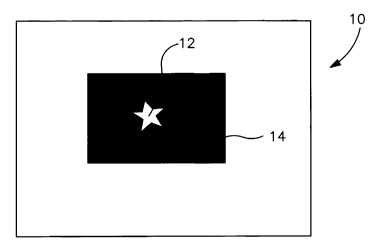
overlapping or non-overlapping relationship. Referring to Fig. 1A, for
instance,
?5 one embodiment of a patterned substrate 10 is shown in which an ink 12 is
printed
on top of an activated carbon ink 14 in an overlapping relationship. Fig. 1 B
illustrates an alternative embodiment in which the activated carbon ink 14 is
printed on top of the ink 12. In either case, the top ink generally does not
cover
the entire surface area of the bottom ink. This is to ensure that the
activated
30 carbon ink is able to contact and adsorb odorous compounds, and that a
clear
pattern is observed. For example, the top ink may cover less than about 90%,
in
some embodiments less than about 75%, and in some embodiments, less than
about 50% of the surface area of the bottom ink.
23
CA 02586924 2007-05-11
WO 2006/071313 PCT/US2005/035245
On the other hand, referring to Fig. 2, another substrate 100 is shown that
includes an ink 112 and an activated carbon ink 114 applied in a non-
overlapping
relationship. Such a non-overlapping relationship may provide a variety of
benefits
to the resulting odor control substrate 100. For example, in certain cases,
the
activated carbon ink 114 might have an adverse affect on the flexibility,
absorbency, and/or some other characteristic of the substrate 100. By
minimizing
the area to which the activated carbon ink 114 is applied, any such adverse
affect
is minimized. In addition, a non-overlapping relationship may also provide a
clearer definition of the pattern provided by the inks.
0 E. Articles
The patterned odor control substrate of the present invention may be
employed in a wide range of articles. In one particular embodiment, the
patterned
odor control substrate is used to form a pouch for an absorbent article.
Specifically, many absorbent articles (e.g., feminine hygiene products) are
5 disposed by placing them in a small pouch in which the product is packaged
for sale.
Thus, the odor control substrate of the present invention may be employed in
the
pouch to help reduce odors associated with the dispensed absorbent articles.
Referring to Figs. 3-4, for example, one embodiment of an individually wrapped
absorbent article package 50 is illustrated. As shown, an absorbent article 42
is
:0 carried in the package 50, which for purposes of description only, is shown
as a
feminine care product (e.g., sanitary pad or napkin). The absorbent article 42
may
be folded in any desired pattern to fit in the package 50.
The package 50 includes an elongate piece of wrapper 44 that is folded
and bonded into the desired pouch configuration. For example, the wrapper 44
?5 may be an elongated rectangular piece having a first end 26, an opposite
second
end 28, and generally parallel longitudinal sides 33 and 35 extending between
the
ends 26 and 28. Various other pouch configurations are known and used in the
art for individually packaging feminine care absorbent articles and any such
configuration may be used in a package according to the invention. For
example,
30 various other pouch configurations are disclosed in U.S. Patent Nos.
6,716,203 to
Sorebo, et al. and 6,380,445 to Moder, et al., as well as U.S. Patent
Application
Publication No. 2003/0116462 to Sorebo, et al., all of which are incorporated
herein in their entirety by reference thereto for all purposes. In the
illustrated
24
CA 02586924 2007-05-11
WO 2006/071313 PCT/US2005/035245
embodiment, for example, a pouch 40 is shown that is similar to the pouch
configuration used for Kotex Ultrathin pads available from Kimberly-Clark
Corporation.
The wrapper 44 is essentially folded around the absorbent article 42 such
that the pouch 40 is formed around the article. The wrapper 44 is first folded
at a
first fold axis 30 such that the first end 26 is folded towards but spaced
from the
second end 28. The distance between the first end 26 and second end 28 may
vary depending on the desired length of a resulting flap 20, as described
below.
The aligned longitudinal sides of the wrapper 44 define sides 34 and 36 of the
0 pouch 40. The second end 28 of the wrapper 44 is then folded at a second
fold
axis 32 so as to extend back over the first end 26 and thus defines the flap
20 that
closes off the pouch 40. The flap 20 has longitudinal sides 24 and 22 that
align
with the material sides 33 and 35 and pouch sides 34 and 36. The sides of the
pouch 40 are then bonded in a conventional manner, for example with a
5 heat/pressure embossing roll. The flap sides 22 and 24 are bonded to the
material sides 33 and 35 and pouch sides 34 and 36 in a single pass operation.
It
may be the case that the first end 26 of the wrapper 44 extends essentially to
the
second fold axis 32 and, thus, the flap sides 22 and 24 would be bonded along
their entire length to pouch sides 34 and 36. The edge of the second end 28
may
:0 extend across the front surface of the pouch 40. It may be desired to
adhere all or
a portion of this edge to the pouch surface. However, in a desirable
embodiment,
this edge is left un-adhered to the pouch between its bonded sides 22 and 24.
Regardless of the particular pouch configuration, the wrapper 44 may be
formed from a variety of different materials, including a film, a fibrous
material
!5 (e.g., nonwoven web), and combinations thereof. For example, the wrapper 44
may sometimes contain a breathable film. In one particular embodiment, the
odor
control substrate of the present invention is used to form one or materials of
the
wrapper 44. Typically, when utilized in this manner, it is desired that the
pattern of
inks is visible to the user and also capable of adsorbing odorous compounds.
For
30 example, as shown, a pattern 80 of an activated carbon ink 84 is applied
over a
colored ink 82. In this particular embodiment, the inks 82 and 84 are present
on
an inner surface 61 of the wrapper 44 so that they are more readily able to
contact
odorous compounds stemming from the absorbent article 42. Alternatively,
CA 02586924 2007-05-11
WO 2006/071313 PCT/US2005/035245
however, the inks 82 and/or 84 may also be present on other surfaces of the
wrapper 44, such as an outer surface 63.
Besides being used in a pouch configuration, the substrate may also be
used in one or more components of an absorbent article, such as in a liquid-
permeable layer (e.g., bodyside liner, surge layer, etc.), liquid-impermeable
or
breathable layer (e.g., outer cover, ventilation layer, baffle, etc.),
absorbent core,
elastic member, and so forth. Several examples of such absorbent articles are
described in U.S. Patent Nos. 5,197,959 to Buell; 5,085,654 to Buell;
5,634,916 to
Lavon, et al.; 5,569,234 to Buell, et al.; 5,716,349 to Taylor, et al.;
4,950,264 to
0 Osborn, III; 5,009,653 to Osborn, III; 5,509,914 to Osborn, III; 5,649,916
to
DiPalma, et al.; 5,267,992 to Van Tillburg; 4,687,478 to Van Tillburg;
4,285,343 to
McNair; 4,608,047 to Mattingly; 5,342,342 to Kitaoka; 5,190,563 to Herron, et
al.;
5,702,378 to Widlund, et al.; 5,308,346 to Sneller, et al.; 6,110,158 to
Kielpikowski; 6,663,611 to Blaney, et al.; and WO 99/00093 to Patterson, et
al.,
5 which are incorporated herein in their entirety by reference thereto for all
purposes.
The odor control substrate of the present invention is versatile and may also
be used with other types of articles of manufacture. For instance, the odor
control
substrate may be used in air filters, such as house filters, vent filters,
disposable
:0 facemasks, and facemask filters. Exemplary facemasks, for instance, are
described and shown, for example, in U.S. Patent Nos. 4,802,473; 4,969,457;
5,322,061; 5,383,450; 5,553,608; 5,020,533; 5,813,398; and 6,427,693, which
are
incorporated herein in their entirety by reference thereto for all purposes.
In one
embodiment, the odor control substrate of the present invention may be
utilized as
05 a filtration layer of the facemask. Filtration layers, such as meltblown
nonwoven
webs, spunbond nonwoven webs, and laminates thereof, are well known in the
art.
In still other embodiments, the odor control substrate may be employed in
conjunction with a garment. For instance, garments, such as meat and seafood
packing industry aprons/attire, grocery store aprons, paper mill
aprons/attire,
30 farm/dairy garments, huntirig garments, etc., may be incorporated with the
odor
control substrate of the present invention. As an example, hunters often wear
garments that are camouflaged for the particular hunting environment. The odor
control substrate of the present invention may thus be used to form the
patterned
26
CA 02586924 2007-05-11
WO 2006/071313 PCT/US2005/035245
camouflage pattern. Specifically, the odor control substrate may impart the
desired color pattern and also help reduce human odor during hunting. In
addition, the odor control coating may be employed on a cover for pet beds,
chairs, elder care / hospital bed covers, infant/children cribs, and so forth.
The effectiveness of the odor control substrate of the present invention in
reducing odor may be measured in a variety of ways. For example, the percent
of
an odorous compound adsorbed by the odor control substrate may be determined
using the headspace gas chromatography test as set forth herein. In some
embodiments, for instance, the odor control substrate of the present invention
is
capable of adsorbing at least about 25%, in some embodiments at least about
45%, and in some embodiments, at least about 65% of a particular odorous
compound. The effectiveness of the activated carbon ink in removing odors may
also be measured in terms of "Relative Adsorption Efficiency", which is also
determined using headspace gas chromatography and measured in terms of
5 milligrams of odor adsorbed per gram of the activated carbon ink. It should
be
recognized that the surface chemistry of any one type of activated carbon ink
may
not be suitable to reduce all types of odors, and that low adsorption of one
or more
odorous compounds may be compensated by good adsorption of other odorous
compounds.
0 The present invention may be better understood with reference to the
following examples.
Test Methods
Quantitative odor adsorption was determined in the Examples using a test
known as "Headspace Gas Chromatography." Headspace gas chromatography
5 testing was conducted on an Agilent Technologies 5890, Series II gas
chromatograph with an Agilent Technology 7694 headspace sampler (Agilent
Technologies, Waldbronn, Germany). Helium was used as the carrier gas
(injection port pressure: 12.7 psig; headspace vial pressure: 15.8 psig;
supply line
pressure is at 60 psig). A DB-624 column was used for the odorous compound
~ that had a length of 30 meters and an internal diameter of 0.25 millimeters.
Such
a column is available from J&W Scientific, Inc. of Folsom, California.
The operating parameters used for the headspace gas chromatography are
shown below in Table 1:
27
CA 02586924 2007-05-11
WO 2006/071313 PCT/US2005/035245
Table 1. Operating Parameters for the Headspace Gas Chromatography
Device.
Headspace Parameters
Oven 37
Zone Temps, C Loop 85
TR. Line 90
GC Cycle time 10.0
Vial eq. Time 10.0
Event Time, minutes Pressuriz. Time 0.20
Loop fill time 0.20
Loop eq. Time 0.15
In'ect time 0.30
First vial 1
Vial Parameters Last vial 1
Shake loffl
The test procedure involved placing 0.005 to 0.1 grams of a sample in a 20
cubic centimeter (cc) headspace vial. Using a syringe, an aliquot of an
odorous
compound was also placed in the vial. Specifically, testing was done with 2.0
micrograms of ethyl mercaptan (2.4 microliters) and 1.8 micrograms (2
microliters)
of dimethyldisulfide. The samples were tested in triplicate. After ten
minutes, a
hollow needle was inserted through the septum and into the vial. A 1-cubic
0 centimeter sample of the headspace (air inside the vial) was then injected
into the
gas chromatograph. Initially, a control vial with only the aliquot of odorous
compound was tested to define 0% odorous compound adsorption. To calculate
the amount of headspace odorous compound removed by the sample, the peak
area for the odorous compound from the vial with the sample was compared to
the
5 peak area from the odorous compound control vial.
EXAMPLE 1
The ability to apply activated carbon ink to a substrate was demonstrated.
The activated carbon ink was obtained from MeadWestvaco Corp. under the name
"Nuchar PMA", and contained 15 wt.% activated carbon, 12 wt.% styrene-acrylic
?0 copolymer binder, and 73 wt.% water. Flat steel rolls were used in a
standard off-
set gravure printing system (obtained from Faustel Inc. of Germantown,
Wisconsin) to uniformly print the activated carbon ink onto one side of the
polyethylene film. The film had a basis weight of 27.1 grams per square meter,
and had been previously exposed to a corona discharge treatment as is well
28
CA 02586924 2007-05-11
WO 2006/071313 PCT/US2005/035245
known in the art. After printing, the films were dried with a through-air
dryer at a
temperature of 190 F for approximately 5 seconds. Seven (7) different samples
were printed with the activated carbon ink in the above-described manner, each
having varying coating weights and print patterns. The line speeds and coating
weights (also calculated as solids add-on level) used for the activated carbon
samples are set forth below in Table 2.
Table 2: Activated Carbon Samples
_Sample Line,~Speed for Coating Weight Solids Add-On
Printing (gsm) Level (%)
ft/min .:
Control - - -
1 100 8.5 31.4
2 100 2.8 10.3
3 100 2.8 10.3
4 100 3.5 12.9
5 100 0.6 2.2
6 1000 4.3 15.9
7 1000 4.3 15.9
Several of the samples were then tested for their ability to remove ethyl
0 mercaptan and dimethylsulfide odorous compounds using the headspace gas
chromatography test described above. The results are set forth below in Table
3.
Table 3: Odor Reduction
Sample Ethyl.Mercaptan.DimethyJtlisulfide % removed !o removed)
1 66.0 61.5
2 45.0 71.8
4 56.0 71.4
5 35.9 55.9
The above odor reduction data was then employed to obtain a correlation
between coating weight and the percent coverage (i.e., print pattern). The
study
measured the odor adsorption capacity for different sample areas having the
same
coating weight. In other words, different sample sizes were cut out from the
same
coated film, and the odor capacity was then measured. This was repeated for
all
the films having different coating weights. Referring to Fig. 5, a graph is
depicted
?0 of the resulting odor adsorption isotherms for each coating. From this
graph, one
may determine the coating weight (or solids add-on level) required for a
desired
print area and odor capacity. Alternatively, one may also determine the print
area
29
CA 02586924 2007-05-11
WO 2006/071313 PCT/US2005/035245
required for a desired coating weight (or solids add-on level) and odor
capacity.
EXAMPLE 2
The ability to apply activated carbon ink to a substrate in a certain pattern
was demonstrated. The activated carbon ink was obtained from MeadWestvaco
Corp. under the name "Nuchar PMA", and contained 15 wt.% activated carbon, 12
wt.% styrene-acrylic copolymer binder, and 73 wt.% water. Gravure steel rolls
were used in a standard off-set gravure printing system (obtained from Faustel
Inc.
of Germantown, Wisconsin) to print the activated carbon ink onto one side of
the
polyethylene film. The film had a basis weight of 27.1 grams per square meter,
0 and had been previously exposed to a corona discharge treatment as is well
known in the art. After printing, the films were dried with a through-air
dryer at a
temperature of 190 F for approximately 5 seconds.
The activated carbon ink was printed in a floral pattern on the film at
various
coating weights (or solids add-on levels) and patterns. Several of the samples
5 were then tested for their ability to remove ethyl mercaptan odorous
compounds
using the headspace gas chromatography device described above. The results
are set forth below in Table 4.
Table 4: Activated Carbon Samples
Sample Line Coating Solids Add- Surface Ethyl
Speed Weight On Level Area Mercaptan
(ft/min) (gsm) ( Io) Covered (%
%0)_ removed)
8 100 6 22.1 25 20
9 100 6 22.1 75 58
100 4 14.8 25 16
11 100 4 14.8 75 50
'.0 While the invention has been described in detail with respect to the
specific
embodiments thereof, it will be appreciated that those skilled in the art,
upon
attaining an understanding of the foregoing, may readily conceive of
alterations to,
variations of, and equivalents to these embodiments. Accordingly, the scope of
the present invention should be assessed as that of the appended claims and
any
?5 equivalents thereto.