Note: Descriptions are shown in the official language in which they were submitted.
CA 02586994 2007-05-08
DESCRIPTION
HEAT SINK AND COOLING UNIT USING THE SAME
TECHNICAL FIELD
[0001] -
The present invention relates to a heat sink for cooling
a heating element formed from electronic components or the like,
particularly, a heat sink having a structure in which forced
convection is used for cooling. The invention also relates
to a cooling unit to which the above heat sink is connected.
BACKGROUND ART
[0002]
JP-A-2002-170915 (referred to as a prior art,
hereinafter) discloses the above kind of conventional heat
sink. The conventional heat sink comprises a heat transfer
vessel provided inside with a channel and a heat transfer
accelerator (such as a fin or a turbulent flow accelerator)
in the channel. In the heat transfer vessel, formed are an
entrance side space for a cooling fluid and an exit side space
for the cooling fluid. Making the cooling fluid flow from the
entrance side space to the exit side space causes a base plate
to be cooled, and thereby, electronic components mounted to
the base plate to be cooled. The entrance side space for the
cooling fluid and the exit side space for the cooling fluid
1
CA 02586994 2007-05-08
are provided separately on the ends of the both sides of the
heat transfer vessel as shown in Fig. 3 of the prior art or
formed on the same end on one side of the heat transfer vessel
so as to be separated from each other as shown in Fig. 2 of
the prior art.
[0003]
Patent Reference 1: JP-A-2002-170915
DISCLOSURE OF THE INVENTION
PROBLEMS THAT THE INVENTION IS TO SOLVE
[0004]
In the conventional heat sink in which the entrance side
space for the cooling fluid and the exit side space for the
cooling fluid are separately provided on the both sides of the
heat transfer vessel, a cooling fluid inlet in the entrance
side space for the cooling fluid and a cooling fluid outlet
in the exit side space for the cooling fluid are provided so
as to be largely separated in location. This requires spaces
for laying pipes to the cooling fluid inlet and the cooling
fluid outlet, respectively, and further requires spaces for
detaching pipes in maintenance. This causes a problem that
the volume of a whole cooling system to be increased.
Moreover, in the above case, some cooling systems are
difficult to share components since the length of the pipes
is not same when a heat sink and pump or a fan are connected
in series in laying the pipes to form a cooling system. In
2
CA 02586994 2007-05-08
addition, long pipes due to the above cause increase in pressure
loss occurring in the cooling system. This causes a problem
that the flow rate in circulation of the cooing fluid and a
heat characteristic are deteriorated.
[0005]
It may be possible to provide a header for distribution
in the entrance side space for the cooling fluid and a header
for confluence in the exit side space for the cooling fluid.
The header for distribution and the header for confluence,
however, playa roll to control deviation in flow in the channel
of the heat transfer vessel and the cross-sections in flow in
the respective headers are usually larger in area than the
cross-section of the channel of the heat transfer vessel.
Accordingly, the headers are respectively formed on the both
ends of the heat transfer vessel in the case of a heat sink
in which the headers are formed on the both ends of the heat
transfer vessel, so that problems are caused such that an access
surface is small in the vicinity of the heating element mounted
on the heat transfer vessel and that an unnecessary space exists
in the back of a part for mounting the heating element.
[0006]
Furthermore, in the case of separately providing the
entrance side part and the exit side part for the cooling fluid
on one side of the heat transfer vessel, the channel in the
heat transfer vessel is a long series channel. Accordingly,
3
CA 02586994 2007-05-08
the cooling fluid receives heat from the heating element in
passing through the channel in the heat transfer vessel to rise
in temperature, so that the cooling fluid at an outflow part
is higher in temperature than the cooling fluid at an inflow
part. This causes a problem that a difference in temperature
is increased in a surface for mounting the heating element.
In the case of forming number of channels in the heat transfer
vessel to form a parallel channel for the purpose of solving
the above problem, there is also a problem that the volume of
the heat sink is increased since the respective channels are
crossed each other or a multiple U-turn part is formed.
[0007]
The invention is to solve the above-mentioned problems.
An object of the invention is to provide a heat sink volume
of making a cooling system more compact. Another object of
the invention is to provide a heat sink superior in uniformity
of heat. Further another object of the invention is to provide
a cooling unit, which is compact and superior in uniformity
of heat.
MEANS FOR SOLVING THE PROBLEMS
[0008]
A heat sink according to the invention is a heat sink
comprising: a header for distribution connected to a cooling
fluid inlet; a header for confluence connected to a cooling
fluid outlet and provided in parallel and adjacently to the
4
CA 02586994 2007-05-08
header for distribution; and a heat transfer vessel including
a heating element mounting surface as well as at least one or
more channel inside, the channel connected to the header for
distribution and the header for confluence.
[0009]
Moreover, a cooling unit according tb the invention is
a cooling unit comprising: several heat sinks respectively
including a header for distribution, a header for confluence
provided in parallel and adjacently to the header for
distribution and a heat transfer vessel including a heating
element mounting surface as well as at least one or more channel
inside, the channel connected to the header for distribution
and the header for confluence; a connecting opening for
connecting the respective headers for distribution of the heat
sinks; a connecting opening for connecting the respective
headers for confluence of the heat sinks; a cooling fluid inlet
connected to the header for distribution of any of the heat
sinks; and a cooling fluid outlet connected to the header for
confluence of any of the heat sinks, the cooling unit wherein
the channels in the respective heat transfer vessels of the
heat sinks communicate with each other.
EFFECT OF THE INVENTION
[0010]
In the heat sink according to the invention, a header
for distribution is provided adjacently and in parallel to a
CA 02586994 2009-05-11
header for confluence. This allows the cooling system to be
made more compact and a heat sink superior in uniformity of
heat to be provided.
[0011]
Further, piling in layers plural heat sinks in which a
header for distribution and a header for confluence are
provided in parallel and adjacently to each other allows a
cooling unit, which is compact and superior in.uniformity of
heat, to be provided.
BRIEF DESCRIPTION OF THE DRAWINGS
[Fig. 1] Fig. 1 shows a structure of a heat sink in accordance
with Embodiment 1 of the invention.
[Fig. 2] Fig. 2 shows a structure of another heat sink in
accordance with Embodiment 1 of the invention.
[Fig. 3] Fig. 3 is a perspective view showing a heat transfer
accelerator in accordance with Embodiment 1 of the invention.
[Fig. 4] Fig. 4 is a perspective view showing another heat
transfer accelerator in accordance with Embodiment 1 of the
invention.
[Fig. 5] Fig. 5 shows a structure of a heat sink in accordance
with Embodiment 2 of the invention.
[Fig. 6] Fig. 6 shows a structure of another heat sink in
accordance with Embodiment 2 of the invention.
[Fig. 7] Fig. 7 shows a structure of further another heat sink
in accordance with Embodiment 2 of the invention.
[Fig. 8] Fig. 8 shows a structure of a heat sink in accordance
with Embodiment 3 of the invention.
6
CA 02586994 2009-05-11
[Fig. 9] Fig. 9 shows a structure of another heat sink in
accordance with Embodiment 3 of the invention.
[Fig. 10] Fig. 10 shows a structure of further another heat
sink in accordance with Embodiment 3 of the invention.
[Fig. 11 ] Fig. 11 shows a structure of a heat sink in accordance
with Embodiment 4 of the invention.
[Fig. 12] Fig. 12 shows a structure of another heat sink in
accordance with Embodiment 4 of the invention.
[Fig. 13] Fig. 13 shows a structure of further another heat
sink in accordance with Embodiment 4 of the invention.
[Fig. 14] Fig. 14 shows a structure of a heat sink in accordance
with Embodiment 5 of the invention.
[Fig. 15] Fig. 15 shows a structure of another heat sink in
accordance with Embodiment 5 of the invention.
[Fig. 16] Fig. 16 shows a structure of a heat sink in accordance
with Embodiment 6 of the invention.
[Fig. 17 ] Fig. 17 is a perspective view showing an integrated
structural body of a rectifying structure and a heat transfer
accelerator in accordance with Embodiment 6 of the invention.
[Fig. 18] Fig. 18 is a structural view showing a heat sink in
accordance with Embodiment 7 of the invention.
[Fig. 19] -Fig. 19 is a structural view showing another heat
sink in accordance with Embodiment 7 of the invention.
[Fig. 20] Fig. 20 shows a cooling unit in accordance with
Embodiment 8 of the invention.
6a
CA 02586994 2009-05-11
[Fig. 21 ] Fig. 21 shows another cooling unit in accordance with
Embodiment 8 of the invention.
[Fig. 22] Fig. 22 shows further another cooling unit in
accordance with Embodiment 8 of the invention.
BEST MODE FOR CARRYING OUT THE INVENTION
[0012]
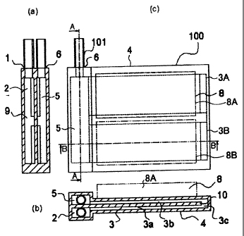
Embodiment 1
Fig. 1 shows a simplified structure of a heat sink in
accordance with Embodiment 1 of the invention. Fig. 1(c) is
a top view of the heat sink. Fig. 1(a) is a sectional view
taken along a line A-A in Fig. 1(c) . Fig. 1(b) is a sectional
view taken along a line B-B in Fig. 1(c). Fig. 2 illustrates
another structure of the heat sink in accordance with
Embodiment 1 of the invention. Fig. 2(c) is a top view of the
heat sink. Fig. 2(a) is a sectional view taken along a line
A-A in Fig. 2(c). Fig. 2(b) is a sectional view taken along
a line B-B in Fig. 2(c).
[0013]
In Figs. 1 and 2, a heat sink 100 forms a cooling system
for cooling a heating element 8 mounted thereto. The heat sink
6b
CA 02586994 2007-05-08
100 comprises: a cooling fluid inlet 1 through which a cooling
fluid 9 of low temperature enters; a header for distribution
2 for dividing the entered cooling fluid 9; a heat transfer
vessel 4 thermally connected to the heating element 8, which
is provided on a heating element mounting surface, and provided
inside with a channel 3; a header for confluence 5 into which
the cooling fluid 9 of high temperature due to absorption of
heat from the heating element 8 flows; and a cooling fluid
outlet 6 from which the confluent cooling fluid 9 is discharged.
The heat sink 100 thus forms a series of flowing channels. The
header for distribution 2 and the header for confluence 5 in
Embodiment 1 are provided in parallel and adjacent to one side
end, concretely, a left side end of the heat sink 100. The
header for distribution 2 and the header for confluence 5 are
provided in parallel vertically in a thickness direction of
the heat transfer vessel 4 and are piled adjacently to each
other in the thickness direction of the heat transfer vessel
4 in a structure in Fig. 1. They are provided in parallel
adjacently on the same side of a heat transfer surface of the
heat transfer vessel 4, that is, a heating element mounting
surface so as to be adjacent to each other in a direction
crossing at right angles with the thickness direction of the
heat transfer vessel 4 in a structure in Fig. 2. In the
structure in Fig. 2, the heat sink 100 is thinner in thickness,
and thereby, more compact than the heat sink 100 having the
7
CA 02586994 2007-05-08
structure in Fig. 1. The channel 3 comprises two channels 3A
and 3B provided in parallel to each other. Each of the channels
3A and 3B is arranged to have a going channel 3a and a returning
channel 3b, which are connected by means of a U-turn channel
3c. The going channel 3a and the returning channel 3b are piled
vertically through a middre plate 10, which forms a partition,
to form a double-layered structure. The header for
distribution 2 is connected with the going channels 3a of the
respective channels 3A and 3B while the header for confluence
is connected to the returning channels 3b of the respective
channels 3A and 3B. The cooling fluid inlet 1 is provided on
an end of the header for distribution 2. The cooling fluid
outlet 6 is provided on an end of the header for confluence
5. The heating element 8, which is a subject to cooling, is
mounted in contact with the heat transfer vessel 4 to be
thermally connected thereto.
[0014]
Connecting a pump or a fan to the heat sink 100 having
such a structure through a pipe 101 allows a cooling system
in which the cooling fluid 9 flows in the heat sink 100 to waste
heat generated from the heating element 8 around the heating
element 8, namely, an open type cooling system to be formed.
Moreover, using the pipe 101 to connect the heat sink
100 with a radiator to further form a distribution loop for
circulation allows a circulation type cooling system to be
8
CA 02586994 2007-05-08
formed. A reservoir and a filter may be provided in a halfway
point of the distribution loop. In this case, the cooling
fluid 9 circulates in the distribution loop to carry the heat
generated from the heating element 8 to the radiator from which
the heat is wasted outside.
Moreover, plural heat sinks 100 having a structure shown
in Embodiment 1 may be connected in series or in parallel
through the pipe 101 to form a series type cooling unit or a
parallel type cooling unit.
[0015]
In Embodiment 1, the channel 3 comprises two channels
3A and 3B as shown in Figs. 1(c) and 2 (c) , the channels 3A and
3B respectively including the going channel 3a, the U-turn
channel 3c and the returning channel 3b and being connected
to the header for distribution 2 and the header for confluence
in parallel to each other. The invention, however, is not
limited to the above. The channel 3 may be a single channel
or formed from three or more channels connected in parallel.
[0016]
Furthermore, a flowing direction of the cooling fluid
is not specifically limited. A relation in location or
functions may be exchangeable between the cooling fluid inlet
I and the cooling fluid outlet 6, the header for distribution
2 and the header for confluence 5 or the going channel 3a and
the returning channel 3b of the channel 3.
9
CA 02586994 2007-05-08
[0017]
In addition, as shown in Figs. 1(c) and 2 (c) , the heating
element 8 also includes two heating elements 8A and 8B, which
are mounted to the heat transfer vessel 4 at places
corresponding to the channels 3A and 3B respectively to be
cooled by means of the cooling fluid flowing in the respective
channels 3A and 3B. The invention, however, is not limited
to the above. It may be arranged that one heating element 8
be provided correspondingly to two or more channels 3 to be
cooled by means of the cooling fluid flowing in 'the respective
channels.
[0018]
Moreover, the heat sink 100 in Embodiment 1 is formed
from the heat transfer vessel 4, the header for distribution
2 and the header for confluence 5, which are formed into one
body. It may be possible, however, that the header for
distribution 2, the header for confluence 5 and the heat
transfer vessel 4 are assembled into one body after they are
formed individually. The heat transfer vessel 4 may be divided
into an upper plate, a middle plate and a bottom plate in forming.
The heat transfer vessel 4 may be also formed into a structure
of piled layers formed from a cladding material. A method of
manufacturing the heat sink, a method of manufacturing
respective divided elements and a method of assembling the
respective elements, namely, a method of fixing and a method
CA 02586994 2007-05-08
of sealing are not specifically limited.
[0019)
An operation of the heat sink 100 in Embodiment 1 will
be described now. In Fig. 1, the cooling fluid 9 entered from
the cooling fluid inlet 1 to the header for distribution 2,
a cooling medium, for example, is divided into-the two channels
3A and 3B in the heat transfer vessel 4. The cooling fluid
9 having flowed into the heat transfer vessel 4 passes through
the going channels 3a (lower channels) in the respective
channels 3A and 3B, makes a U-turn through the U-turn channel
3c provided at the right end of the heat sink 100, passes through
the returning channels 3b (upper channels), flows into the
header for confluence 5 to be confluent and flows to the cooling
fluid outlet 6. At that time, a wall of the returning channel
3b of the heat transfer vessel 4 directly contacting with the
heating elements 8A and 8B, namely, a side wall on which the
heating elements 8A and 8B are provided receives heat to rise
in temperature. This causes a difference in temperature
between the cooling fluid 9 in the returning channel 3b and
the wall of the returning channel 3b, so that heat is
transferred from the wall of the returning channel 3b to the
cooling fluid 9. As a result, the cooling fluid 9 rises in
temperature to be discharged from the cooling fluid outlet 6.
On the other hand, the cooling fluid 9 in the returning channel
3b becomes higher in temperature than the cooling fluid 9 in
11
CA 02586994 2007-05-08
the going channel 3a (in the lower channel) due to a rise in
temperature of the cooling fluid 9 in the returning channel
3b. This causes the heat to be transferred from the cooling
fluid 9 in the returning channel 3b to the cooling fluid 9 in
the going channel 3a through the middle plate 10, which is a
partition betteen the going channel 3a and the returning
channel 3b. As a result, the cooling fluid 9 in the going
channel 3a receives heat to rise in temperature while the
cooling fluid 9 in the returning channel 3b is cooled. This
causes a rise in temperature of the cooling fluid 9 in the
returning channel 3b to be decreased, and thereby, deviation
in temperature in mounting surfaces of the heating elements
8A and 8B to be reduced, so that uniformity of heat is improved.
As described above, the cooling fluid 9 passes through the
cooling fluid inlet 1, the header for distribution 2, the
channels 3A and 3B in the heat transfer vessel 4, the header
for confluence 5 and the cooling fluid outlet 6 in order, rises
in temperature to a high degree in passing through the channels
3A and 3B and is continuously discharged with its temperature
being high.
(0020]
Generally, the cooling fluid in a downstream channel is
higher in temperature than the.cooling fluid in an upstream
channel when the cooling fluid flowing in a channel receives
heat from a channel wall of the heat transfer vessel especially
12
CA 02586994 2007-05-08
T
on a side provided with the heating element to rise in
temperature to a high degree. Accordingly, temperature of a
heating element mounting surface located on a downstream side
of the channel is higher than that of a heating element mounting
surface located on an upstream side of the channel, so that
deviation in temperature in a heating element mounting surface
is large. This causes a problem that the deviation in
temperature causes dispersion in electric characteristic,
which disables a desired function to be achieved, in the case
of using electronics as the heating element, for example. The
deviation in temperature also causes deviation in electric
resistance, so that a problem such as deviation in calorific
value (local heating, hot spot) and thermal run-away occurs.
[0021]
In Embodiment 1, however, a range of a change in
temperature of the cooling fluid 9 inside the going channel
3a and the returning channel 3b is narrow since the channels
3A and 3B have a folded double-layered structure and heat
exchange is carried out between the cooling fluid 9 flowing
in the going channel 3a and the cooling fluid 9 flowing in the
returning channel 3b through the middle plate 10. Accordingly,
the deviation in temperature in a mounting surface of the
heating element 8 is made small, and thereby, the uniformity
of heat is improved, so that the above-mentioned problem can
be prevented.
13
CA 02586994 2007-05-08
[0022]
Further, in a conventional heat sink, a cooling fluid
inlet and a cooling fluid outlet, which are separately provided,
require large spaces for laying pipes in putting the heat sink
in a cooling system, as described above. In the case of
providing a connector for -detachment in the middle of a pipe
in order to carry out detachment in maintenance, spaces for
carrying out the detachment should be respectively secured,
so that the capacity of the cooling system becomes large. As
a conventional heat sink, also used having been a heat sink
having a continuous meandering channel. In this case, it is
possible to provide a cooling fluid inlet and a cooling fluid
outlet adjacently to each other. This causes a problem,
however, that a loss in pressure becomes large in the case of
a long channel due to a large size of heat sink, the flow rate
in circulation of the cooling fluid is reduced, and thereby,
a heat characteristic is deteriorated. There is also a problem
that a rise in temperature of the cooling fluid causes large
deviation in temperature in a heating element mounting surface,
as described above. Moreover, in the case of increasing the
width of a cooling part of the channel or providing the channels
in parallel for the purpose of reducing the loss in pressure,
the cooling fluid flow is easily biased in the channel and
deviation in temperature in a heating element mounting surface
is large. This is also a problem.
14
CA 02586994 2007-05-08
[0023]
In Embodiment 1, however, the header for distribution
2 and the header for confluence 5, which are provided in
parallel on one side of the heat sink 100, so that the cooling
fluid inlet 1 and the cooling fluid outlet 6 can be provided
closely. Accordingly, the spaces required for the cooling
fluid inlet 1 and the cooling fluid outlet 6, respectively,
can be shared, so that the cooling system can be made compact.
[0024]
Furthermore, in Embodiment 1, providing the header for
distribution 2 and the header for confluence 5 in parallel on
one side of the heat sink 100 allows an access surface to the
heating elements 8, 8A and 8B mounted to the heat sink 100 to
be large, so that more flexible wiring is possible.
[0025]
In addition, as shown in Figs. 1(c) and 2 (c) , the cooling
fluid inlet 1 and the cooling fluid outlet 6 can be provided
closely at a corner of one side surface of the heat sink 100,
so that wiring passing above the header for distribution 2 and
the header for confluence 5 can be easily carried out.
[0026]
In Figs. 1 and 2, a direction almost vertical to extending
lines of the going channels 3a and the returning channels 3b
of the channels 3A and 3B is defined as a longitudinal direction
of the header for distribution 2 and the header for confluence
CA 02586994 2007-05-08
5. The cooling fluid 9 is sent from the cooling fluid inlet
1 in the longitudinal direction of the header for distribution
2. The cooling fluid is discharged from the cooling fluid
outlet 6 in the longitudinal direction of the header for
confluence 5. Especially, the header for distribution 2 is
connected in its longitudinal direction-to the respective
going channels 3a of the channels 3A and 3B. Accordingly, the
cooling fluid sent in the longitudinal direction of the header
for distribution 2 allows the going channels 3a of the
respective channels 3A and 3B to be supplied with the almost
equal cooling fluid. When the cooling fluid is sent from one
place in a direction crossing at right angles with the
longitudinal direction of the header for distribution 2, the
cooling fluid concentrates in the going channel 3a closer to
the place from which the cooling fluid is sent while the other
going channel 3a can not be supplied with enough cooling fluid.
Further, the channel parts can be easily provided in
parallel independently from each other in Embodiment 1, so that
a loss in pressure can be reduced, and thereby, it can be made
difficult to generate a one-sided drift in the channels.
[0027]
In Figs. 1 and 2, simply shown were the heating elements
8A and 8B in the shape of a block. The structure and size of
the heating elements 8A and 8B, however, are not specifically
limited so long as the heating elements are what applies heat
16
CA 02586994 2007-05-08
to the heat sink 100, such as a heat generating source for a
heater, electronics and an electronic component, a heat
generating source formed by integrating the above, a heat
radiating part of an apparatus for transferring heat from the
above heat generating sources and a heat exchanger including
a heat sink in accordance with the invention, for example.
[0028]
The heating elements 8A and 8B are fixed to the heat
transfer vessel 4 by soldering, brazing, or pressure welding
or thermally connected through a contact heat resistance
reducing agent (including a' sheet) such as thermal grease. The
structure of the heating elements is not specifically limited
as long as the heating elements 8A and 8B can be thermally
connected with the cooling fluid 9.
[0029]
The heating elements 8 may be provided in one heat sink
100 in single or plural number. Furthermore, the heating
elements 8 may be provided on any of an upper surface, a lower
surface and both surfaces of the heat sink 100.
In the case that the heating elements 8 are provided on
the both surfaces of the heat sink 100, the heat sink may be
fixed so that the heating elements 8 would hold the heat sink
therebetween.
[0030]
Inside the heat transfer vessel 4, formed are the
17
CA 02586994 2007-05-08
channels 3A and 3B as described above. The channels 3A and
3B play a role of a container of the cooling fluid 9 and a passage
through which the cooling fluid 9 flows. The channels 3A and
3B also play a role of thermally connecting the heating elements
8A and 8B with the cooling fluid 9 as well as diffusing and
uniforming heat transferred from the heating elements 8A and
8B. Accordingly, heat transfer accelerators 11 may be
provided in the channels 3A and 3B in order to accelerate heat
transfer from the wall surfaces of the channels 3A and 3B to
the cooling fluid 9. As the heat transfer accelerator 11,
considered can be an insertion such as a fin having both of
a heat transfer surface area enlarging effect and a heat
transfer improving effect due to turbulent acceleration, for
example, a projection substantially in the shape of a plate
or a column, the projection provided on a channel wall, and
a turbulent accelerator having the heat transfer improving
effect due to turbulent acceleration, for example, various
shapes of projection provided on a channel wall faced to the
heating element mounting surface, a ribbon, a coil, an inner
fin shown in Fig. 3, various shapes of projection shown in Fig.
4 and a substrate having plural openings, for example.
[0031]
A heat transfer accelerator divided into plural numbers
may be adjacently provided or plural heat transfer
accelerators may be provided with any gap in providing the heat
18
CA 02586994 2007-05-08
transfer accelerator 11 in the channel. Further, a
rectification reinforcement may be provided in a gap between
heat transfer accelerators chiefly for the purpose of
reinforcement of the channels 3A and 3B.
The rectification reinforcement is for reinforcing
upper and lower wall surfaces forming the channels 3A and 3B
by means of a spring structure, a beam structure or the like.
A structure of the rectification reinforcement is not
specifically limited so long as flowing channels are secured
while a change in form of the upper and lower wall surfaces
of the channels 3A and 3B can be prevented. The rectification
reinforcement also has a role of mixing and rectifying the
cooling fluid 9 in some cases.
[0032]
The middle plate 10 has a role of exchanging heat between
the cooling fluid 9 in the going channel 3a and the cooling
fluid 9 in the returning channel 3b. A heat transfer
accelerator having a structure similar to that of the heat
transfer accelerator 11 may be provided on a surface of the
middle plate 10.
[0033]
The U-turn channel 3c connecting the going channel 3a
and the returning channel 3b may be in the shape of an elbow
or a bend. A shape and a structure of the U-turn channel 3c
is not specifically limited so long as the U-turn channel 3c
19
CA 02586994 2007-05-08
can play a role of a passage connecting the going channel 3a
and the returning channel 3b.
The heat transfer vessel 4 can be also used for fixing
the heating element 8 and components accompanying thereto.
Moreover, it may be possible to provide a fixing jig for a
through hole or a screw hole for the attachment to peripheral
apparatuses such as a cooling system, for example.
[0034]
The heat sink 100 shown in Fig. 1 has a structure that
the heating elements 8A and 8B are in contact with a wall of
the heat transfer vessel 4, namely, an indirect cooling
structure. The heat sink 100, however, may have a structure
that the heating elements 8A and 8B are fitted in an opening
15 provided in the heat transfer vessel 4, namely, a direct
cooling structure, as shown in Fig. 2. This causes lower
surfaces of the heating elements 8A and 8B to be directly in
contact with the cooling fluid 9, and thus, heat is directly
transferred from the heating elements 8A and 8B to the cooling
fluid 9. This allows the contact heat resistance generated
between the heating elements 8A and 8B and the wall of the heat
transfer vessel 4 in indirect cooling to be eliminated, and
thereby, the heat characteristic to be improved. The opening
15 may also be provided in the heat sink 100 in single or plural
number similarly to the heating element 8. The opening 15 may
be provided on any of an upper surface, a lower surface and
CA 02586994 2007-05-08
both surfaces. Moreover, projections or convexes for
positioning may be provided circularly or intermittently on
the surface of the heat transfer vessel around the opening 15
in order to make positioning of the heating elements 8A and
8B easy.
[0035]
The heat transfer vessel 4 and the heating elements 8A
and 8B in the direct cooling structure may be fixed by means
of a jig such as a bolt and a nut or a spring structure using
a leaf spring and such. As a method of sealing the heat transfer
vessel 4 and the heating elements 8A and 8B, considered may
be welding or gluing. It is also possible to use a gasket or
an 0-ring to form a detachable structure. A sealing structure
is not specifically limited so long as the cooling fluid 9 can
be prevented from leaking and the heating elements 8A and 8B
can be thermally connected to the cooling fluid 9 directly.
[0036]
The header for distribution 2 plays a role of dividing
the cooling fluid 9 sent from the cooling fluid inlet 1 and
leading the same to the channels 3A and 3B. The header for
distribution 2 further plays a role of preventing a one-sided
drift in a single channel or a one-sided drift in plural
parallel channels 3A and 3B. The header for confluence 5 plays
a role of leading the cooling fluid 9 flowing from the channels
3A and 3B to. the cooling fluid outlet 6. The header for
21
CA 02586994 2007-05-08
confluence 5 further plays a role of preventing a one-sided
drift in a single channel or a one-sided drift in plural
parallel channels 3A and 3B, similarly to the header for
distribution 2.
[0037]
Ih the header for distribution 2 and the header for
confluence 5, may be provided a rectifying structure for
preventing a one-sided drift in the channels 3A and 3B such
as a plate provided with plural holes, a plate provided with
plural slits, a net-shaped plate, a projection provided on a
header wall or a combination of the above plural components,
for example. Especially, a curved projection (a guide blade)
or a bending channel may be provided on a wall of the header
for confluence 5 in order to change a flowing direction of the
cooling fluid 9 flowing from the channels 3A and 3B into a
direction to the downstream side of the header for confluence
5, that is, a direction substantially toward the cooling fluid
outlet 6.
[0038]
In the heat sink 100 shown in Fig. 1, the header for
distribution 2 and the header for confluence 5, which are
provided in parallel, are provided symmetrically with respect
to the middle plate 10 and the respective headers 2 and 5 have
a same cross-section. The cross sections of the respective
headers 2 and 5 are not necessarily same. The oblateness of
22
CA 02586994 2007-05-08
the above may be difference and any one of the cross sections
may be larger. The shape of the cross section is not
specifically limited. A circle, an ellipse and a rectangular
may be considerable.
Furthermore, in the heat sink 100 in Fig. 2, the header
for distribution 2 and the header for confluence 5, which are
provided in parallel, are provided on a same surface side with
respect to the middle plate 10. In this case, the cross
sections of the respective headers may be in any shape. The
height of an outer frame of a header part formed from the header
for distribution 2 and the header for confluence 5, however,
is preferably fixed as shown in Fig. 2. This allows a wiring
plate or the like to be easily fitted to the heating elements
8A and 8B.
[0039]
The cooling fluid inlet 1 plays a role of sending the
cooling fluid 9 of a low temperature. On the other hand, the
cooling fluid outlet 6 plays a role of discharging the cooling
fluid 9 of a high temperature. The cooling fluid inlet 1 and
the cooling fluid outlet 6 are connected to a pipe 101 such
as a circular pipe, a rectangular pipe, a flexible tube or a
hose, for example. The cooling fluid inlet 1 and the cooling
fluid outlet 6 are preferably in a flat shape when the cross
section of the header for distribution 2 or the header for
confluence 5 is in a flat shape. The pipe 101 is also preferable
23
CA 02586994 2007-05-08
to be a pipe smoothly flatted in the vicinity of a part connected
with the cooling fluid inlet 1 and the cooling fluid outlet
6 so as to be connected to the same.
[0040]
In Figs. 1 and 2, shown are structures that the pipe 101
is fixed to the cooling fluid inlet 1 and the cooling fluid
outlet 6 or that the cooling fluid inlet 1 and the cooling fluid
outlet 6 are formed into one body with the pipe 101. The
invention is not specifically limited to the structure. A
structure that a pipe with a nipple is fixed or a structure
that an O-ring or a gasket is used to connect the pipe 101 or
the similar heat sink 100 may be considerable.
[0041]
In addition, the cooling fluid inlet 1 and the cooling
fluid outlet 6 are provided adjacently on an upper side surface
on a left corner in Figs. 1 and 2. The invention is not limited
to the structure. Location for providing the cooling fluid
inlet 1 and the cooling fluid outlet 6 may be selected on wall
surfaces of the header for distribution 2 and the header for
confluence 5, which are adjacently provided, properly in
forming the cooling system.
[0042]
A material for forming the heat sink 100 is preferable
to be a material having high heat conductivity. The heat sink
100 can be preferably formed from a material superior in heat
24
CA 02586994 2007-05-08
transfer characteristic, that is, metal such as aluminum and
copper or a compound material including the above as a main
material, for example. Especially, the mounting surfaces of
the heating elements 8A and 8B of the heat transfer vessel 4,
the walls of the channels 3A and 3B and the middle plate 10
are preferable to be formed from a material superior in heat
transfer characteristic. On the other hand, a part other than
the above may be molded with a resin material in view of easiness
in molding and a low cost although the part may be also formed
from a similar metal material described above. In the case
that a part of the heat transfer vessel 4 is molded with a resin
material, a metal plate such as a stainless plate, for example,
may be provided on at least a part of the surface.
[0043]
This allows deformation due to a change of the resin
material according to the passage of time to be kept down.
Particularly, fixing the heat transfer vessel 4 by holding the
same between the heating elements 8A and 8B or jigs for fixing
the heating elements 8A and 8B and the metal plate enables the
effect to be enlarged.
A part of the metal plate may be bared in the channels
3A and 3B so that the metal plate would be in contact with the
cooling fluid=9. This allows a withstand voltage test, which
is carried out when the electronics or the like are provided
as the heating elements 8A and 8B, to be easily performed.
CA 02586994 2007-05-08
[0044]
The metal plate has only to be provided on the heat
transfer vessel 4. A size and a fitting method of the metal
plate are not specifically limited. The metal plate may be
fixed by means of a fixing jig such as a bolt or by vacuum
evaporation, deposition and gluing. Further, the cooling
fluid 9 should be arranged to be prevented from leaking from
a bared part of the metal plate in the channels 3A and 3B when
the part of the metal plate is bared. Accordingly, the metal
plate may be closely fixed through an O-ring or a gasket.
[0045]
The cooling fluid 9 is a liquid such as distilled water,
antif reez ing solution, oil, liquid carbon dioxide, alcohol and
ammonia or a gas such as air and nitrogen gas.
[0046]
Embodiment 2
Fig. 5 shows a simplified structure of a heat sink in
accordance with Embodiment 2 of the invention. Fig. 5(c) is
a top view of the heat sink. Fig. 5(a) is a sectional view
taken along a line A-A in Fig. 5(c). Fig. 5(b) is a sectional
view taken along a line B-B in Fig. 5 (c) . Fig. 6 shows another
structure of the heat sink in accordance with Embodiment 2 of
the invention. Fig. 6 (c) is a top view of the heat sink. Fig.
6 (a) is a sectional view taken along a line A-A in Fig. 6(c).
Fig. 6(b) is a sectional view taken along a line B-B in Fig.
26
CA 02586994 2007-05-08
6(c).
[0047]
In the heat sink 100 in accordance with Embodiment 2,
the channel 3 formed in the heat transfer vessel 4 is formed
from two channels 3A and 3B, as shown in Figs. 5 and 6. The
respective channels 3A and 3B are formed on one same plane to
form a single-layered channel, namely, a single channel plane.
That is to say, Embodiment 1 has a double-layered channel
structure that the going channels 3a and the returning channels
3b of the respective channels 3A and 3B are formed in the
thickness direction of the heat transfer vessel 4 and the
respective channels 3A and 3B are folded in the thickness
direction. On the other hand, the respective channels 3A and
3B are formed on one same plane in the heat transfer vessel
4 in Embodiment 2. Each of the channels 3A and 3B is arranged
to have the going channel 3a and the returning channel 3b on
a same plane and turns in the U-turn channel 3c formed on the
plane same as that of the going channel 3a and the returning
channel 3b. Further, the header for distribution 2 and the
header for confluence5 are provided in parallel and adjacently
to each other on the left side of the heat sink 100, similarly
to Embodiment 1. In Embodiment 2, however, it is arranged that
any one of the header for distribution 2 and the header for
confluence 5 be offset with respect to a single channel plane
on which the respective channels 3A and 3B are provided and
27
CA 02586994 2007-05-08
the offset header 2 or 5 be connected to the respective channels
3A and 3B through connecting channels. The header for
distribution 2 communicates with each of the going channels
3a of the respective channels 3A and 3B while the header for
confluence 5 communicates with each of the returning channels
3b of the respective channels 3A and 3B.
[0048]
In a structure in Fig. 5, the header for distribution
2 and the header for confluence 5 are provided vertically in
the thickness direction of the heat transfer vessel 4 so as
to hold therebetween the single channel plane on which the
respective channels 3A and 3B are provided. Both of the header
for distribution 2 and the header for confluence 5 are offset
with a predetermined interval in the thickness direction of
the heat transfer vessel 4 with respect to the single channel
plane on which the respective channels 3A and 3B are provided.
The header for distribution 2 is arranged to communicate with
each of the going channels 3a of the respective channels 3A
and 3B through a connecting channel 16a connected to a
connecting opening provided in the header 2. The header for
confluence 5 is arranged to communicate with each of the
returning channels 3b of the respective channels 3A and 3B
through a connecting channel 16b connected to a connecting
opening provided in the header 5.
[0049]
28
CA 02586994 2007-05-08
In a structure in Fig. 6, the header for distribution
2 and the header for confluence 5 are provided adjacently on
a same side of a heat transfer surface of the heat transfer
vessel 4. The header for distribution 2 of the two headers
2 and 5, the header for distribution 2 being provided on the
outer side, is connected to each of the going channels 3a of
the respective channels 3A and 3B formed on the single channel
plane through a connecting channel 16c. The header for
confluence 5 of the two headers 2 and 5, the header for
confluence 5 being provided on the inner side, namely, on the
heat transfer vessel 4 side, is offset with a predetermined
interval in the thickness direction of the heat transfer vessel
4 with respect to the single channel plane on which the
respective channels 3A and 3B are provided. The header for
confluence 5 is arranged to communicate with each of the
returning channels 3b of the respective channels 3A and 3B
through a connecting channel 16d connected to a connecting
opening provided in the header for confluence 5.
[0050]
This allows the heat transfer vessel 4 to be made thin
in thickness and more compact. Moreover, the two channels 3A
and 3B can be provided in parallel in order without crossing
although the channels 3A and 3B are formed in the single channel
plane.
In Fig. 6, a direction substantially vertical to an
29
CA 02586994 2007-05-08
extending line of the goring channels 3a and the returning
channels 3b of the channels 3A and 3B is also defined as a
longitudinal direction of the header for distribution 2 and
the header for confluence 5. The cooling fluid 9 is sent from
the cooling fluid inlet 1 in the longitudinal direction of the
header for distribution 2. The cooling fluid is discharged
from the cooling fluid outlet 6 in the longitudinal direction
of the header for confluence 5. Especially, sending the
cooling fluid in the longitudinal direction of the header for
distribution 2 allows the going channels of the respective
channels 3A and 3B to be supplied with substantially equal
cooling fluid since the header for distribution 2 is connected
to each of the going channels 3a of the channels 3A and 3B in
the longitudinal direction of the header for distribution 2.
[0051]
In Embodiment 2, the cooling fluid 9 in the returning
channels 3b is higher in temperature than the cooling fluid
9 in the going channels 3a in the respective channels 3A and
3B. A series of the channels 3A and 3B comprising the going
channels 3a, the U-turn channels 3c and the returning channels
3b, however, can be provided adjacently and in parallel in
plural number, so that heat diffusion in the heat transfer
vessel 4 or the heating elements 8A and 8B of the heat transfer
vessel 4 operates effectively. This allows the deviation in
temperature in the mounting surface of the heating elements
CA 02586994 2007-05-08
8A and 8B to be made small and the uniformity of heat to be
improved. The uniformity of heat is improved more when the
more plural channels 3A, 3B, 3C ... of small channel width are
provided in parallel, particularly. The heating elements 8A
and 8B are fixed to the heat transfer vessel 4 at places
corresponding to the channels 3A and 3B, respectively.
[0052]
The plural channels 3A and 3B are provided orderly so
that the going channel 3a of the channel 3A would be adjacent
to the returning channel 3b of the channel 3B in the structure
in Fig. 5. It may be possible to arrange the respective going
channels 3a of the adjacent channels 3A and 3B adjacently to
each other so that the channels 3A and 3B would be provided
symmetrically, as shown in Fig. 6. Further, in Fig. 6, the
respective returning channels 3b of the adjacent channels 3A
and 3B may be provided adjacently to each other so that the
channels 3A and 3B would be provided symmetrically. An
arrangement of the channels 3A and 3B is not limited as
described above.
[0053]
Moreover, the flowing direction of the cooling fluid is
not specifically limited. A relation in location or functions
may be exchangeable between the cooling fluid inlet 1 and the
cooling fluid outlet 6, the header for distribution 2 and the
header for confluence 5 or the going channels 3a and the
31
CA 02586994 2007-05-08
returning channels 3b of the channels 3A and 3B.
[0054]
In addition, the U-turn channel 3c connecting the going
channel 3a and the returning channel 3b may be in the shape
of an elbow or a bend. A shape of the U-turn channel 3c is
not specifically limited.
It is, however, preferable to provide a guide blade such
as a wing-shaped projection for controlling a one-sided drift
and a separation flow, for example, in the U-turn channel 3c.
[0055]
Fig. 7 shows further another structure of the heat sink
in accordance with Embodiment 2. Fig. 7(c) is a top view of
the heat sink. Fig. 7(a) is a sectional view taken along a
line A-A in Fig. 7(c). Fig. 7(b) is a sectional view taken
along a line B-B in Fig. 7(c).
In the heat sink 100 in Figs. 5 and 6, the respective
headers 2 and 5 are mounted on one side of the heat transfer
vessel 4. The respective headers 2 and 5, however, are
provided 'at the substantial center of the heat transfer vessel
4 in the heat sink 100 in Fig. 7. In a structure in Fig. 7,
the header for distribution 2 and the header for confluence
5, which are provided in parallel, are located at the center
and wing-shaped heat transfer vessels 4A and 4B are provided
on the both sides of the header for distribution 2 and the header
for confluence 5. Two channels 3A and 3B are formed in a single
32
CA 02586994 2007-05-08
channel plane of the heat transfer vessel 4A. In the same
single channel plane of the heat transfer vessel 4B, also formed
are two channels 3C and 3D. Each of the channels 3A, 3B, 3C
and 3D includes a going channel 3a, a U-turn channel 3c and
a returning channel 3b.
Such a structure allows the heat trans ferrvessels 4A and
4B, namely, mounting surfaces of the heating elements 8A, 8B,
BC and 8D to be provided on the both sides of the respective
headers 2 and 5. Moreover, the above structure allows the
heating elements 8A, 8B, 8C and 8D to be more freely arranged
as well as allowing access to the heating elements 8A, 8B, 8C
and 8D such as wiring to be made easier. The heating elements
BA, 8B, 8C and 8D are fixed to the heat transfer vessels 4A
and 4B at places corresponding to the channels 3A, 3B, 3C and
3D, respectively, in the structure in Fig. 7.
[0056]
In Fig. 7, a connecting opening D of the header for
distribution 2 is provided at a place marked with "D" and a
connecting opening E of the header for confluence 5 is provided
at a place marked with "E" so that the connecting openings D
and E would be adjacent to each other. The header for
distribution 2 is provided with two connecting openings D,
which communicate with the respective going channels 3a of the
channels 3A and 3B. The header for confluence 5 is also
provided with two connecting openings E, which communicate
33
CA 02586994 2007-05-08
with the respective returning channels 3b of the channels 3C
and 3D. The returning channel 3b of the channel 3A and the
going channel 3a of the channel 3C communicate with each other
via a connecting opening F. The channels 3A and 3C are
connected in series between the connecting opening D of the
header for distribution 2 and the connecting opening E of the
header for confluence 5. The returning channel 3b of the
channel 3B and the going channel 3a of the channel 3D also
communicate with each other via a connecting opening F. The
channels 3B and 3D are connected in series between the
connecting opening D of the header for distribution 2 and the
connecting opening E of the header for confluence 5. In this
structure, the cooling fluid 9 flows from the header for
distribution 2 into the channels 3A and 3B in the left heat
transfer vessel 4A, passes through the upper part of the headers
2 and 5, and then, flows in the channels 3C and 3D in the right
heat transfer vessel 4B into the header for confluence 5.
It may be possible in Fig. 7 that channel ends G of the
channels 3A and 3C are connected to form a loop channel while
channels ends G of the channels 3B and 3D are connected to form
a loop channel, although it is omitted from the drawing. In
this case, the two connecting openings D of the header for
distribution 2 are arranged to be provided at places marked
with "D" while two connection openings H of the header for
confluence 5 are arranged to be provided at places marked with
34
CA 02586994 2007-05-08
"H11. This allows the cooling fluid 9 flowing from the header
for distribution 2 into the loop channel to be divided into
right and left. One of the divided cooling fluids 9 passes
through the channels 3A and 3B in the left heat transfer vessel
4A and flows above the headers 2 and 5 to be sent to the header
of confluence 5. The other cooling fluid 9 flows above the
header 2 and 5 and passes through the channels 3C and 3D in
the right heat transfer vessel 4B to be sent to the header for
confluence 5 again. Accordingly, the flowing length is
shortened and a fluid characteristic is improved, so that the
heat characteristic including the uniformity of heat improved.
[0057]
In Fig. 7, shown is an example that the heat transfer
vessel 4 is in the shape of a flat plate. The invention, however,
is not limited to the above. The heat transfer vessel 4 may
be substantially in the shape of V, U, a square or 0 (including
a heat transfer vessel whose ends are connected to each other) .
The similar shapes are considerable for the heat transfer
vessel 4 also in Figs. 1 to 6.
[0058]
Embodiment 3
Fig. 8 shows a simplified structure of a heat sink in
accordance with Embodiment 3 of the invention. Fig. 8(c) is
a top view of the heat sink. Fig. 8(a) is a sectional view
taken along a line A-A in Fig. 8 (c) . Fig. 8 (b) is a sectional
CA 02586994 2007-05-08
view taken along a line B-B in Fig. 8(c).
The heat sink 100 in Embodiment 3 is arranged to have
a mixing channel 18 through which the U-turn channels 3c in
the middle part of the channels 3A and 3B communicate with each
other. Ranges of a rise in temperature of the cooling fluid
9 in the respective channels 3A and 3B are different in the
case that plural, two, for example, heating elements 8A and
8B are provided at places corresponding to the channels 3A and
3B and the respective heating elements 8A and 8B have different
calorific values. Mixing the cooling fluid 9 flowing in the
respective channels 3A and 3B in the middle of the channels
3A and 3B allows the temperature of the cooling fluid 9 to be
made equal. That is to say, the maximum temperature of the
cooling fluid 9 decreases. Sending the mixed cooling fluid
9 into the channels 3A and 3B again allows the uniformity of
heat in the heat sink 100 to be improved, so that the heat
characteristic is improved.
In the heat sink 100 in Fig. 8, shown is an example in
which the U-turn channels 3c of the channels 3B and 3A in the
heat sink 100 in Fig. 6 are connected via the mixing channel
18. The cooling fluid 9 having risen in temperature in the
going channels 3a is arranged to be mixed in the mixing channel
18 to be sent to the returning channels 3b.
The header for distribution 2 in the heat sink 100 in
Fig. 8 communicates with each of the going channels 3a of the
36
CA 02586994 2007-05-08
respective channels 3A and 3B through the connecting channel
16c while the header for confluence 5 communicates with each
of the returning channels 3b of the respective channels 3A and
3B through the connecting channel 16d.
[0059]
It is preferable to provide in the mixing channel 18 a
mixture accelerator, namely, an insertion such as a plate
provided with plural holes, a plate provided.with plural slits,
a net, a twisted tape and a coil, a projection provided on the
inner wall of the mixing channel 18 or combination of some of
the above, for example. The mixture accelerator may have a
structure same as that of the rectification reinforcement
described in Embodiment 1.
[0060]
Fig. 9 shows another structure of the heat sink in
accordance with Embodiment 3 of the invention. Fig. 9(e) is
a top view of the heat sink. Fig. 9(a) is a sectional view
taken along a line A-A in Fig. 9(e) . Fig. 9(b) is a sectional
view taken along a line B-B in Fig. 9(e). Fig. 9(c) is a
sectional view taken along a line C-C in Fig. 9(e). Fig. 9(d)
is a sectional view taken along a line D-D in Fig. 9(e).
In the heat sink 100 shown in Fig. 9, the respective
returning channels 3b of the two channels 3A and 3B are adjacent
to each other at the center of the heat transfer vessel 4. A
projection, that is, a mixture accelerator 19 on a side wall
37
CA 02586994 2007-05-08
in the mixing channel 18 for connecting the respective
returning channels 3b of the channels 3A and 3B is provided
to form an upper channel 20 and a lower channel 21 in the mixing
channel 18. On the other hand, in the mixing channel 18 for
connecting the respective going channels 3a of the channels
3A and 3B, the going channels 3a located at the both ends of
the heat sink 100, provided are partition plates 22 for making
partitions between the returning channels 3b and the going
channels 3a. The partition plate 22 is arranged to be provided
with an opening 23 so that each going channel 3a would be
connected to any one of the upper channel 20 and the lower
channel 21.
[0061]
This allows the cooling fluid 9 flowing in the respective
going channels 3a of the channels 3A and 3B of the heat sink
100 to flow from the openings 23 respectively provided in the
partition plates 22 into the upper channels 20 or the lower
channels 21 in the mixing channel 18 and to be mixed in the
mixing channel 18 connected with the returning channels 3b,
so that the mixed cooling fluid 9 can flow in the respective
returning channels 3b of the channels 3A and 3B.
In the heat sink 100 in Fig. 9, the header for
distribution 2 communicates with each of the going channels
3a of the respective channels 3A and 3B through the connecting
channel 16c while the header for conf luence 5 communicates with
38
CA 02586994 2007-05-08
each of the returning channels 3b of the respective channels
3A and 3B through the connecting channel 16d.
In Figs. 8 and 9, a direction almost vertical to an
extending lines of the going channels 3a and the returning
channels 3b of the channels 3A and 3B is also defined as a
longitudinal direction of the header for distribution 2 and
the header for confluence 5. The cooling fluid 9 is sent from
the cooling fluid inlet 1 in the longitudinal direction of the
header for distribution 2. The cooling fluid is discharged
from the cooling fluid outlet 6 in the longitudinal direction
of the header for confluence 5. Especially, the header for
distribution 2 is connected in its longitudinal direction to
the respective going channels 3a of the channels 3A and 3B.
Accordingly, the cooling fluid sent in the longitudinal
direction of the header for distribution 2 allows the going
channels 3a of the channels 3A and 3B to be supplied with the
almost equal cooling fluid.
[ 0062
In Fig. 9, the flowing direction of the cooling fluid
is not especially. limited. The similar effects can be expected
even when a relation in location or functions is exchanged
between the cooling fluid inlet 1 and the cooling fluid outlet
6, the header for distribution 2 and the header for confluence
or the going channels 3a and the returning channels 3b of
the channels 3A and 3B.
39
CA 02586994 2007-05-08
[0063]
Fig. 10 shows further another structure of the heat sink
in accordance-with Embodiment 3 of the invention. Fig. 10(e)
is a top view of the heat sink. Fig. 10 (a) is a sectional view
taken along a line A-A in Fig. 10(e). Fig. 10(b) is a sectional
view taken along a line B-B in Fig. 10(e). Fig. 10(c) is a
sectional view taken along a line C-C in Fig. 10 (e). Fig. 10 (d)
is a sectional view taken along a line D-D in Fig. 10(e).
In the heat sink 100 shown in Fig. 10, the respective
returning channels 3b of the two channels 3A and 3B are adjacent
to each other at the center of the heat transfer vessel 4. Two
partition plates 25 provided with plural openings 24 are
provided in the mixing channel 18 connected to the respective
returning channels 3b of the channels 3A and 3B to form three
of upper, middle and lower channels. On the other hand, in
the mixing channel 18 connected to the respective going
channels 3a of the channels 3A and 3B, the going channels
located at the both ends of the heat transfer vessels 4,
provided are partition plates 22 for making partition between
the returning channels 3b and the going channels 3a. The
partition plate 22 is arranged to be provided with an opening
23 so that each going channel 3a would be connected to any one
of the upper channel 20 and the lower channel 21. In this case,
the cooling fluid 9 flowing in the respective going channels
3a of the channels 3A and 3B, the going channels located at
CA 02586994 2007-05-08
the both ends of the heat transfer vessel 4, flows from the
openings 23 provided in the partition plates 22 into the upper
channel 20 or the lower channel 21 in the mixing channel 18,
flows from the openings 24 provided in plural number in the
partition plates 25 into the middle channel 26. The cooling
fluid 9 is then mixed in-the mixing channel 18 connected to
the returning channels 3b. The mixed cooling fluid 9 is thus
able to flow in each of the returning channels 3b of the
respective channels 3A and 3B.
In the heat sink 100 in Fig. 9, the header for
distribution 2 communicates with each of the going channels
3a of the respective channels 3A and 3B through the connecting
channel 16c while the header for confluence 5 communicates with
each of the returning channels 3b of the respective channels
3A and 3B through the connecting channel 16d.
[0064]
In Fig. 10, the flowing direction of the cooling fluid
is also not specifically limited. The similar effects can be
expected even when a relation in location or functions is
exchanged between the cooling fluid inlet 1 and the cooling
fluid outlet 6, the header for distribution 2 and the header
for confluence 5 or the going channels 3a and the returning
channels 3b of the channels 3A and 3B.
[0065]
The above effect can be also expected when the
41
CA 02586994 2007-05-08
temperature distribution of the cooling fluid is large in a
cross section of a channel even in the case of forming one
channel 3 in the heat transfer vessel 4. Properly providing
the partition plate 22 and the opening 23 allows the effect
similar to that of the cases in Figs. 9 and 10 to be achieved
even in the case of providing tiree or more channels 3 in
parallel.
[0066]
Embodiment 4
Fig. 11 shows a simplified structure of a heat sink in
accordance with Embodiment 4 of the invention. Fig. 11(c) is
a top view of the heat sink. Fig. 11(a) is a left side view
of the heat sink. Fig. 11(b) is a sectional view taken along
a line B-B in Fig. 11(c) . Fig. 12 shows a simplified structure
of another heat sink in accordance with Embodiment 4 of the
invention. Fig. 12(c) is a top view of the heat sink. Fig.
12(a) is a left side view of the heat sink. Fig. 12(b) is a
sectional view taken along a line B-B in Fig. 12(c).
[0067]
In the heat sink 100 in Embodiment 4, the header for
distribution 2 and the header for confluence 5 are provided
in parallel on the left side of the heat sink 100 so at to be
offset with respect to a surface on which the channels 3A and
3B are provided, as shown in Figs. 11 and 12. Further, the
header for distribution 2 on the left side, namely, the outer
42
CA 02586994 2007-05-08
side is arranged to be shorter than the header for confluence
on the right side, namely, the inner side. The header for
distribution 2 communicates with each of the going channels
3a of the respective channels 3A and 3B through the connecting
channel 16c. The header for confluence 5 communicates with
each of the returning channels 3b of the respective channels
3A and 3B through the connecting channel 16d. In the heat sink
100 shown in Fig. 11, it is arranged that two cooling fluid
inlets 1 and 1' be formed for the header for distribution 2
while two cooling fluid outlets 6 and 6' be formed for the header
for confluence 5 so that the pipe 101 can be respectively
connected to any of the cooling fluid inlets 1 and 1' and any
of the cooling fluid outlets 6 and 6'. Accordingly, more
flexible pipe laying is available in accordance with a setting
condition. In the heat sink 100 shown in Fig. 12, the longer
header for confluence 5 on the inner side is formed into the
shape of L to be lead to the left side end surface of the heat
sink 100. This allows the cooling fluid inlet 1 and the cooling
fluid outlet 6 to be provided on the left side end surface of
the heat sink 100, namely, a surface crossing at right angles
with a direction in which the respective headers 2 and 5 are
adjacent. Accordingly, more flexible pipe laying is possible,
so that the cooling system can be made compact. The header
for confluence 5 of the heat sink 100 shown in Fig. 12 can
achieve the similar effect even when it is formed into the shape
43
CA 02586994 2007-05-08
of C.
[0068]
Piling the plural heat sinks 100 provided with the pipe
101 on its left side end as shown in Fig. 11 to form a stack
structure so as to form a cooling unit in which the plural heat
sinks 190 are connected allows pipe mounting-places of the
respective heat sinks 100 to be unified at the left side upper
part or lower part, so that the cooling system can be made more
compact. Moreover, the heat sink in Embodiment 4 have five
surfaces capable of pipe laying since the left side surface
is also possible to be used for laying a pipe although the heat
sinks 100 shown in Figs. 6, 8 and 9 have four surfaces capable
of pipe laying. This allows more flexible pipe laying to be
achieved. In addition, only three surfaces of the left side
surface, the upper surface and the lower surface are the surface
from which all the heat sinks can be seen in the case of a stack
structure. This is especially effective when the respective
heat sinks 100 are connected to independently provided headers
in a cooling fluid circulation loop, the headers being provided
separately from the respective heat sinks 100.
[0069]
The respective heat sinks 100 shown in Figs. 1 to 6 and
8 to 10 have a direction since the headers 2 and 5 are thicker
in thickness than the heat transfer vessel 4 and both surfaces
of the heat sink 100 are different in shape. Accordingly, one
44
CA 02586994 2007-05-08
kind of heat sink 100 can be used for forming the above structure
in the case of piling the heat sinks 100 in a same direction,
but two kinds of heat sinks 100 in which places for providing
the cooling fluid inlet 1 and the cooling fluid outlet 6 are
different should be used in the case of piling the heat sinks
100 so as to be faced to each other. Providing the cooling
fluid inlets 1 and 1' and the cooling fluid outlets 6 and 6'
respectively on both of the upper and lower ends of the both
headers 2 and 5, however, allows the cooling fluid inlets and
the cooling fluid outlets to be respectively provided at the
same height in the upper and lower parts on the left side of
the heat sinks 100 in the stack structure even in the
face-to-face piling structure. Accordingly, upper or lower
cooling fluid inlet and outlet can be selected for laying pipes.
Sealing another set of unselected cooling fluid inlet and
outlet with a water-cutoff cap and such (including a drain
valve) allows the heat sinks to be more flexibly combined to
form a cooling unit. The similar effect can be achieved in
Figs. 1 to 6 and 8 to 10 by similarly providing the cooling
fluid inlets 1 and 1' and the cooling fluid outlets 6 and 6'
respectively on both of the upper and lower ends.
[0070]
Furthermore, in Fig. 11, the cooling fluid 9 is arranged
to flow into the header for distribution 2 or from the header
for confluence 5 so as to cross at right angles with the headers.
CA 02586994 2007-05-08
A direction that the cooling fluid is sent to the header for
distribution 2 is same as a direction that the cooling fluid
is sent to the channels 3A and 3B. Accordingly, much more
cooling fluid 9 flows into one of the channels 3A and 3B, the
one being closer to a part from which the cooling fluid 9 is
sent in the header for distribution 2. This causes a one-sided
drift in the respective channels 3A and 3B or a difference in
drift between the respective channels 3A and 3B in some cases.
Providing a curved channel 27 between the cooling fluid inlet
1 and the header for distribution 2 as shown in Fig. 13 to
arrange the cooling fluid 9 to flow in the longitudinal
direction of the header for distribution 2, namely, a direction
crossing at right angles with a flowing direction of the cooling
fluid in the channels 3A and 3B allows flowing conditions at
the ends of the respective channels 3A and 3B to comparatively
resemble each other since the cooling fluid in the header for
distribution 2 is different in flowing direction from the
cooling fluid in the channels 3A and 3B. This allows the
one-sided drift to be kept down.
The curved channel 27 may be also provided in the
connecting part between the header for confluence 5 and the
cooling fluid outlet 6 in the case that the header for
confluence 5 is provided on the outer side. In this case, the
cooling fluid 9 is sent in the longitudinal direction of the
header for confluence 5, so that substantially equal cooling
46
CA 02586994 2007-05-08
fluid can be discharged from the returning channels 3b of the
respective channels 3A and 3B.
[0071]
Embodiment 5
Fig. 14. shows a simplified structure of a heat sink in
accordance with Embodiment 5 of the invention. Fig. 14(c) is
a top view of the heat sink. Fig. 14(a) is a sectional view
taken along a line A-A in Fig. 14 (c). Fig. 14 (b) is a sectional
view taken along a line B-B in Fig. 14(c).
[0072]
Embodiment 5 is an example of an optimum arrangement of
plural heating elements 8 including a high heat generating
source 28 and a low heat generating source 29 in the heat sink
100 in accordance with the invention. As typical electronics
having high heating density, considered can be a power module.
The power module is formed chiefly from two tips of an IGBT
and a diode, which are provided on a substrate. The power
module is often provided comparatively regularly in an
even-numbered column. Any one of the IGBT and the diode
generates heat more than the other in many cases although it
depends on a condition under which the power module is used,
and therefore, the heat sink 100 is usually used for cooling
for the purpose of keeping the temperature of any high heating
element 28 under a permissible temperature. In Embodiment 5,
defined as the high heat generating source 28 is not what has
47
CA 02586994 2007-05-08
a larger calorific value but what has a larger heat flux, namely,
a larger calorific value per a unit area. As the low heat
generating source 29, defined is what includes a heat
generating source other than the high heat generating source
28.
In Fig. 14, such plural high heat generating sources 28
are provided along the respective going channels 3a of the
channels 3A and 3B while the plural low heat generating sources
29 are provided along the respective returning channels 3b of
the channels 3A and 3B.
[0073]
Such a structure allows the cooling fluid 9 of a low
temperature to receive heat chiefly from lines of the high heat
generating sources 28 to rise in temperature in passing through
the going channels 3a of the respective channels 3A and 3B.
The cooling medium 9 having risen in temperature returns
through the -U-turn channel 3c. In passing through the
returning channels 3b of the respective channels 3A and 3B,
the cooling medium 9 receives heat from lines of the low heat
generating sources 29 to further rise in temperature. The
cooling fluid 9 of high temperature is then discharged from
the cooling fluid outlet 6 through the header for confluence
5. Accordingly, the cooling fluid 9 of lower temperature cools
the lines of the high heat generating sources 28 while, on the
other hand, the cooling fluid 9 having received heat and risen
48
CA 02586994 2007-05-08
in temperature in passing through the going channels 3a cools
the lines of the low heat generating sources 29. This causes
a rise in maximum temperature of the lines of the low heat
generating sources 29 differently from the case of cooling both
of the heat generating sources in any one of the going channel
and the returning channel. The maximum temperature of the
lines of the high heat generating sources 28, however,
decreases, the deviation in temperature in the heating element
8 is reduced, the uniformity of heat is accelerated, and further,
the maximum temperature of the high heat generating sources
28, which is the most important, decreases, so that the heat
characteristic is improved.
In the heat sink 100 in Fig. 14, the header for
distribution 2 communicates with each of the going channels
3a of the respective channels 3A and 3B through the connecting
channel 16c while the header for confluence 5 communicates with
each of the returning channels 3b of the respective channels
3A and 3B through the connecting channel 16d.
[0074]
Fig. 15 shows a simplified structure of another heat sink
in accordance with Embodiment 5 of the invention. Fig. 15(c)
is a top view of the heat sink. Fig. 15 (a) is a sectional view
taken along a line A-A in Fig. 15(c) . Fig. 15(b) is a sectional
view taken along a line B-B in Fig. 15(c). In the heat sink
100 in Fig. 15, the going channels 3a of the channels 3A and
49
CA 02586994 2007-05-08
3B in the heat sink 100 in Fig. 14 are formed to be common.
In the plural heating elements 8 including the high heat
generating sources 28 and the low heat generating sources 29,
a chief heat generating source group including plural high heat
generating sources 28 is provided in two rows along the going
channel 3a while a chief heat generating source peripheral part
including plural low heat generating sources 29 is provided
in two rows so as to be bridged between the going channel 3a
and the returning channel 3b. In the heat sink 100 in Fig.
14, the two channels 3A and 3B are formed on a same plane
independently from each other. In the heat sink 100 in Fig.
15, however, the going channels 3a of the channels 3A and 3B
are formed in common. The goring channel 3a formed in common
communicates with the returning channels 3b of the channels
3A and 3B through the U-turn channels 3c, respectively. The
heat sink 100 in Fig. 15 can also achieve an effect similar
to that of the heat sink 100 in Fig. 14.
[0075]
In the heat sink 100 in Figs. 14 and 15, shown is an example
that the high heat generating sources 28 are provided at the
center of the heat transfer vessel 4. The high heat generating
source 28, however, may be provided on the outer side. Any
structure is possible so long as the high heat generating source
28 or the chief heat generating source group is mainly cooled
in the going channel 3a while the low heat generating source
CA 02586994 2007-05-08
29 or the chief heat generating source peripheral part is mainly
cooled in the returning channel 3b. In other words, any
structure is considerable as long as a heat generating source
mounting part, which is most difficult to satisfy the
permissible temperature, is cooled in the going channel 3a and
the other part is cooled in the returning channel 3b.
[0076]
Embodiment 6
Fig. 16 shows a simplified structure of a heat sink in
accordance with Embodiment 6 of the invention. Fig. 16(b) is
a side sectional view of the heat sink in accordance with
Embodiment 6. Fig. 16(a) is a sectional view taken along a
line A-A in Fig. 16(b). Fig. 16(a) also includes perspective
views of the heat transfer accelerator 11 and a rectifying
structure 13..
[0077]
In the heat sink 100 in Embodiment 6, the heat transfer
accelerators 11 of the length almost same as the heating element
mounting length in the flowing direction of the cooling fluid
are provided in the respective going channels 3a and the
respective returning channels 3b of the channels 3A and 3B
provided just under the heating element mounting surface, as
shown in Fig. 16. Further, a rectifying structure 13 is
provided on at least one of an upstream side and a downstream
side of the heat transfer accelerator 11 at an interval to the
51
CA 02586994 2007-05-08
heat transfer accelerator 11. The length of the heat transfer
accelerator 11 is defined to be the length of the channel
thermally connected to a heat transfer surface between a heat
generating source located on the upstream side and a heat
generating source located on the most downstream side along
the going channel 3a and the returning channel 3b, respectively,
in the case of mounting a heating element including a heat
generating source such as plural IGBTs, for example, that is,
a power module, for example. Fixing projections 30 are
provided respectively on wall surfaces of the channels 3A and
3B where the ends of the heat transfer accelerator 11 and the
rectifying structure 13 are located.
[0078]
Such arrangement causes the one-sided drift in the
channels 3A and 3B to be rectified by means of the rectifying
structure 13 and the cooling fluid 9 whose flow has been evened
to pass through the heat transfer accelerators 11.
Accordingly, heat is effectively transferred to the cooling
fluid 9 from the heating element 8, so that the heat transfer
characteristic is improved. Moreover, a hot spot due to a
one-sided drift or breakaway of the cooling fluid can be kept
down.
It is also arranged in the heat sink 100 in Fig. 16 that
the header for distribution 2 communicate with each of the going
channels 3a of the respective channels 3A and 3B through the
52
CA 02586994 2007-05-08
connecting channel 16c while the header for confluence 5
communicate with each of the returning channels 3b of the
respective channels 3A and 3B through the connecting channel
16d.
[0079]
The fixing projections-30 are provided on the wall
surfaces of the channels 3A and 3B in the heat sink 100 in Fig.
16. On the wall surfaces of the channels 3A and 3B, however,
may be provided fixing concaves to which the heat transfer
accelerator 11 and the rectifying structure 13 can be mounted.
Furthermore, as for the rectification reinforcement
described in Embodiment 1, it may be fixed in a channel by means
of a similar fixing projection 30 or a similar fixing concave.
[0080]
The length of the heat transfer accelerator 11 in the
flowing direction of the cooling fluid may be longer than the
heating element mounting length. In this case, however, the
periphery of the heating element is excessively cooled, and
thereby, the deviation in temperature in the heating element
mounting surface is increased. Moreover, increase in loss in
pressure deteriorates a fluid characteristic and a heat
transfer characteristic. In Embodiment 6, however, provided
are the heat transfer accelerator 11 whose length is almost
same as the heating element mounting length in the flowing
direction, that is, a little shorter than the heating element
53
CA 02586994 2007-05-08
mounting length in Fig. 16 and the rectifying structure 13,
which is spaced from the heat transfer accelerator 11 and which
is provided at a place hardly connected thermally to the heating
element. This allows a one-sided drift to be prevented by
means of the rectifying structure 13. In addition, there is
-no excessive cooled part described above, and thereby, the
deviation in temperature in the heating element mounting
surface decreases, so that the uniformity of heat can be
improved.
[0081]
The length of an interval between the heat transfer
accelerator 11 and the rectifying structure 13 is preferably
twice or more as long as the hydraulic equivalent diameter in
the rectifying structure 13. Such length allows a
rectification effect to be achieved. Further, more effective
is the length of the interval five times or more as long as
the hydraulic equivalent diameter.
[0082]
In the case of using an insertion as the heat transfer
accelerator 11, providing the fixing projection 30 or a fixing
concave as shown in Fig. 16 allows positioning of the heat
transfer accelerator 11 and the rectifying structure 13 to be
accurately carried out and a manufacturing operation to be
easily performed.
Further, it may be also possible to use an integrated
54
CA 02586994 2007-05-08
s y
structural body formed from the rectifying structure 13 and
the heat transfer accelerator 11, which are connected by means
of a connecting part 12, as shown in Fig. 17.
[0083]
Embodiment 7
F' ig. 18 is a simplified perspective view of a heat sink
in accordance with Embodiment 7 of the invention. Fig. 19 is
a simplified perspective view of another heat sink in
accordance with Embodiment 7 of the invention.
[0084]
In the heat sink in Embodiment 7, the heat transfer vessel
4 is formed into a folded structure so as to have a cross section
substantially in the shape of S and includes three flat heat
transfer vessel layers 41, 42 and 43, as shown in Fig. 18. The
three heat transfer vessel layers 41, 42 and 43 of the heat
transfer vessel 4 are provided with the heating elements 8A,
8B and 8C, respectively. This allows a compact heat sink,
which cools the plural heating elements 8A, 8B and 8C, to be
provided. The heat transfer vessel layers 41, 42 and 43 are
respectively formed similarly to the heat transfer vessels 4
in Embodiments 1 to 4.
Fig. 19 shows a heat sink or a cooling unit, which is
formed by dividing the heat transfer vessel 4 having a cross
section substantially in the shape of S into plural vessel
members 4a, 4b and 4c to connect the divided vessel members
CA 02586994 2007-05-08
4a, 4b and 4c with each other. Dividing the heat transfer
vessel 4 allows manufacture to be easily carried out. The
vessel members 4a, 4b and 4c respectively have the heat transfer
vessel layers 41, 42 and 43.
[0085]
The heating elements 8A, 8B and 8C may be arranged to
be cooled only from one surface or from both surfaces.
[0086]
In Embodiment 7, the heat transfer vessel 4 is preferable
to be formed from a material having flexibility. That is to
say, intervals between adjacent heat transfer vessel layers
41, 42 and 43 among the heat transfer vessel layers 41, 42 and
43 of the heat transfer vessel 4 are widened a little to mount
the heating elements 8A, 8B and 8C, and then, all the above
is sandwiched together. This allows the thermal contact
between the heating elements 8A, 8B and 8C and the heat transfer
vessel layers 41, 42 and 43 to be improved. The air-tightness
of the channels 3A and 3B can be improved when the opening 15
described in Embodiment 1 is provided in the heat transfer
vessel 4. Moreover, in the case that the heat transfer vessel
4 is divided, the divided heat transfer vessels 4a, 4b and 4c
can be easily connected.
[0087]
The heat transfer vessel 4 has a cross section
substantially in the shape of S in Embodiment 7 shown in Figs.
56
CA 02586994 2007-05-08
18 and 19. The heat transfer vessel 4, however, is not
specifically limited in structure so long as it has a folded
structure substantially in the shape of a wave such as a
substantial U' shape and a substantial W shape and the heating
element is held between the folded layers.
[0088]
Embodiment 8
Fig. 20 shows a simplified cooling unit in accordance
with Embodiment 8 of the invention for every component. Fig.
20 (A) shows an upper heat sink 100a. Fig. 20 (B) shows a middle
heat sink 100b. Fig. 20(C) shows a lower heat sink 100c. The
heat sinks 100a, 100b and 100c are piled in three layers to
form a cooling unit. In each of Figs. 20(A), 20(B) and 20(C),
(c) is a top-view of the heat sink in each layer, (a) is a
sectional view taken along a line A-A in (c) and (b) is a
sectional view taken along a line B-B in (c)
[0089]
The lower heat sink 100c shown in Fig. 20(C) is a heat
sink having a structure similar to that of Embodiment 2 shown
in Fig. 6, for example, the heat sink being provided with
connecting openings 32 in upper surfaces of the header for
distribution 2 and the header for confluence 5, namely, a piling
surface on which the middle heat sink 100b is piled. The middle
heat sink 100b shown in Fig. 20(B) is a heat sink having a
structure similar to that of Embodiment 2 shown in Fig. 6, for
57
CA 02586994 2007-05-08
example, the heat sink being provided with no cooling fluid
inlet 1 and no cooling fluid outlet 6 and with connecting
openings 32 in upper and lower surfaces of the header for
distribution 2 and the header for confluence 5, namely, piling
surfaces on which the upper and lower heat sinks 100a and 100c
are piled. The upper heat sink 100a shown in Fig. 20(A) is
a heat sink having a structure similar to that of Embodiment
2 shown in Fig. 6, for example, the heat sink being provided
with no cooling fluid inlet 1 and no cooling fluid outlet 6
and with connecting openings 32 in lower surfaces of the header
for distribution 2 and the header for confluence 5, namely,
a piling surface on which the middle heat sink 100b is piled.
A cooling unit shown in Fig. 20 in accordance with Embodiment
8 is formed from the heat sinks 100a, 100b and 100c, which have
the above structures, piled in three layers so that the channels
3A and 3B of the respective heat sinks 100a, 100b and 100c would
be provided in parallel to each other via the connecting
openings 32.
In all of the heat sinks 100a, 100b and 100c, the header
for distribution 2 communicates with the going channels 3a of
the respective channels 3A and 3B through the connecting
channels 16c while the header for confluence 5 communicates
with the returning channels 3b of the respective channels 3A
and 3B through the connecting channels 16d.
[0090]
58
CA 02586994 2007-05-08
Fig. 21 shows another simplified cooling unit in
accordance with Embodiment 8 of the invention for every
component. Fig. 21(A) shows an upper heat sink 100d. Fig.
21 (B) shows a middle heat s ink 10 0 e. Fig . 21(C) shows a lower
heat sink 100f. The heat sinks 100d, 100e and 100f are piled
in three layers to form a cooling unit. In each of Figs. 21(A) ,
21(B) and 21(C), (c) is a top view of the heat sink in each
layer, (a) is a sectional view taken along a line A-A in (c)
and (b) is a sectional view taken along a line B-B in (c).
[0091]
The lower heat sink 100f shown in Fig. 21(C) is arranged
to be provided with the cooling fluid inlet 1 at the end of
the header for distribution 2 and with a connecting opening
320 in an upper surface of the header for confluence 5, namely,
a piling surface on which the middle heat sink 100e is piled.
The lower heat sink 100f is also arranged so that a connecting
opening 321 provided in the upper surface of the heat sink,
namely, on the piling surface on which the middle heat sink
100e is piled would communicate with the cooling fluid outlet
6 separately from the header for confluence 5. In the lower
heat sink 100f, the cooling fluid inlet 1 is provided in the
upper end surface of the header 2 as shown in Fig. 21(C) . The
cooling fluid inlet 1 may be provided on an end surface opposite
to the above. The header for distribution 2 of the lower heat
sink 100f communicates with the going channels 3a of the
59
CA 02586994 2007-05-08
respective channels 3A and 3B through the connecting channels
16c. The header for confluence 5 communicates with the
returning channels 3b of the respective channels 3A and 3B
through the connecting channels 16d.
The middle heat sink 100e shown in Fig. 21(B) is arranged
to be provided with no cooling fluid inlet 1 and no cooling
fluid outlet ,6 and with a connecting opening 320 in a lower
surface of the header for distribution 2, namely, a piling
surface on which the lower heat sink 100f is piled and a
connecting opening 322 in an upper surface of the header for
confluence 5, namely, a piling surface on which the upper heat
sink 100d is piled. The middle heat sink 100e is also arranged
so that a connecting channel 3210 for connecting a connecting
opening 321 of the lower heat sink 100f and an connecting
opening 321 of the upper heat sink 100d would be provided
separately from the header for distribution 2 and the header
for confluence 5. The header for distribution 2 of the middle
heat sink 100e communicates with the going channels 3a of the
respective channels 3A and 3B through the connecting channels
16c. The header for confluence 5 communicates with the
returning channels 3b of the respective channels 3A and 3B
through the connecting channels 16d.
The upper heat sink 100d shown in Fig. 21(A) is arranged
to be provided with no cooling fluid inlet 1 and no cooling
fluid outlet 6 and with a connecting opening 322 in a lower
CA 02586994 2007-05-08
surface of the header for distribution 2, namely, a piling
surface on which the middle heat sink 100e is piled and a
connecting opening 321 on a lower surface of the header for
confluence 5, namely, a piling surface on which the middle heat
sink 100e is piled. The header for distribution 2 of the upper
heat sink 100d communicates with the going channels 3a of the
respective channels 3A and 3B through the connecting channels
16c. The header for confluence 5 communicates with the
returning channels 3b of the respective channels 3A and 3B
through the connecting channels 16d.
The cooling unit shown in Fig. 21 is formed from the heat
sinks 100d, 100e and 100f, which are piled in three layers so
that the channels 3A and 3B of the respective heat sinks 100d,
100e and 100f would be provided in series.
[0092]
Fig. 22 shows further another simplified cooling unit
in accordance with Embodiment 8 of the invention for every
component. Fig. 22(A) shows an upper heat sink 100g. Fig.
22(B) shows a middle heat sink 100h. Fig. 22(C) shows a lower
heat sink 100i. The heat sinks 100g, 100h and 100i are piled
in three layers to form a cooling unit. In each of Figs. 22 (A) ,
22(B) and 22(C), (c) is a top view of the heat sink in each
layer, (a) is a.sectional view taken along a line A-A in (c)
and (b) is a sectional view taken along a line B-B in (c).
[0093]
61
CA 02586994 2007-05-08
The lower heat sink 100i shown in Fig. 22(C) is arranged
to be provided with no cooling fluid outlet 6 and with the
cooling fluid- inlet 1 at the end of the header for distribution
2 and a connecting opening 32 in an upper surface of the header
for confluence 5, namely, a piling surface on which the middle
heat sink l00h is piled. The header for distribution 2 of the
lower heat sink 100i communicates with the going channels 3a
of the respective channels 3A and 3B through the connecting
channels 16c. The header 5 for confluence communicates with
the returning channels 3b of the respective channels 3A and
3B through the connecting channels 16d.
The middle heat sink 100h shown in Fig. 22 (B) is arranged
to be provided with no cooling fluid inlet 1 and no cooling
fluid outlet 6 and with connecting openings 32 in a lower
surface of the header for distribution 2, namely, a piling
surface on which the lower heat sink 100i is piled and in an
upper surface of the header for confluence 5, namely, a piling
surface on which the upper heat sink 100g is piled. The header
for distribution 2 of the middle heat sink 100h communicates
with the going channels 3a of the respective channels 3A and
3B through the connecting channels 16c. The header 5 for
confluence communicates with the returning channels 3b of
the respective channels 3A and 3B through the connecting
channels 16d.
The upper heat sink 100g shown in Fig. 22 (A) is arranged
62
CA 02586994 2007-05-08
to be provided with no cooling fluid inlet I and with a
connecting opening 32 in a lower surface of the header for
distribution 2, namely, a piling surface on which the middle
heat sink 100h is piled and the cooling fluid outlet 6 at the
end of the header for confluence 5. The header for
distribution 2 of the upper heat sink 100g communicates with
the going channels 3a of the respective channels 3A and 3B
through the connecting channels 16c. The header 5 for
confluence communicates with the returning channels 3b of
the respective channels 3A and 3B through the connecting
channels 16d.
The cooling unit shown in Fig. 22 is formed from the heat
sinks 100g, 100h and 100i, which are piled in three layers so
that the channels 3A and 3B of the respective heat sinks 100g,
100h and 100i would be provided in series.
[0094]
Such a structure allows the plural heat sinks to be easily
piled, so that a compact cooling unit can be provided.
[0095]
Structures and connecting methods of the connecting
openings 32, 320, 321 and 322 are not specifically limited so
long as the connecting openings 32, 320, 321 and 322 can be
connected with each other so that the cooling fluid 9 would
flow therein. Two connecting openings may be connected
directly, through an O-ring or a gasket or via a flowing pipe
63
CA 02586994 2007-05-08
(including a bend and an elbow), for example.
[0096]
Further, in Embodiment 8, shown is an example that the
connecting opening 32 is provided in the upper or lower surfaces
of the headers 2 and 5. The invention, however, is not
specifically limited to the above. The cooling unit may be
arranged to be provided with connecting openings in side walls
of the headers 2 and 5 to connect the connecting openings so
that the channels 3A and 3B of the respective heat sinks would
be provided in series or in parallel by means of a U-shaped
bend.
[00971
Moreover, in Embodiment 8, exemplified is a stack
structure formed from plural piled heat sinks. The plural heat
sinks, however, may be provided on any surfaces to be connected
with each other.
The plural heat sinks may also be provided on any surfaces
so that the headers 2 and 5 would be faced to each other so
as to be connected with each other. A structure of integration
is not specifically limited so long as the cooling unit is
formed from a combination of plural heat sinks.
[0098]
A method of mounting each of the heat sinks is not
specifically limited. The heat sinks may be connected
respectively by means of fixing jigs (such as a bolt and nut)
64
CA 02586994 2009-05-11
or mounted to frames or such.
A projection in contact with a heat sink may be provided
on at least any one of the four corners of another heat sink
in order to prevent a change in form of the heat sink.
[0099]
In addition, the structural strength is reduced when a
part of the heat sink is formed from resin. Accordingly, in
a cooling unit formed from plural heat sinks piled, provided
may be fixing plates on the outer sides of the heat sinks on
the both ends to hold the cooling unit between the fixing plates
for the purpose of fixing the cooling unit, for example.
[0100]
In each of the above-mentioned embodiments, a shape of
a cross section of each component, a shape of a channel, a
relative size and such are just exemplifications and not
limited to the description.