Note: Descriptions are shown in the official language in which they were submitted.
CA 02587258 2007-05-10
WO 2006/050900 PCT/EP2005/011921
Appliance and method for preparing a froth from a food
liquid
The present invention relates to an appliance and to a
method for preparing a froth from a food liquid such as
milk and is intended, for example, to be used in the
context of the preparation of beverages such as
cappuccinos, milky coffees, cafe latte and macchiato,
hot chocolate and other speciality hot beverages.
Speciality beverages in which at least a portion is
made up of froth are increasingly becoming all the
rage. The best-known beverage of this type is a coffee
of the cappuccino type. It comprises a liquid portion
consisting of coffee topped by a layer of frothed milk
which, because of its very much lower density, floats
atop the surface of the liquid. In general, preparing
one takes time, manipulation operations and cleaning.
The most customary way of preparing a milk-based froth
is to pour the desired amount of milk into the
container, immerse a steam outlet pipe from a coffee
machine in the container, agitating it up and down to
introduce the air needed to form the froth.
A first disadvantage with this method is that it
entails having a coffee machine equipped with a steam
outlet, and not all machines are.
Another disadvantage lies in the fact that it is
generally not possible to prepare the froth at the same
time as preparing the coffee, unless a complex and
expensive machine with two separate fluid circuits, one
for extracting the coffee and the other for producing
steam, is available.
Another disadvantage associated with the use of coffee
machines with a steam outlet stems from the fact that
the system for heating the water in these machines,
CA 02587258 2007-05-10
WO 2006/050900 PCT/EP2005/011921
- 2 -
most often a thermoblock, has to be kept constantly
switched on in order to produce the steam without
having to wait. These machines therefore consume large
amounts of power, which makes them not very economical
to operate. It must also be noted that steam pipes soon
become scaled up when the water used is hard water and
this entails regular maintenance in order to keep them
in good condition.
Another disadvantage with this type of machine stems
from the fact that the quality of the froth is
dependent on the skill of the user which means that
these machines do not allow the froth obtained to have
reproducible properties and a uniform quality.
Another disadvantage stems from the fact that the pipes
in contact with the milk are difficult and not very
practical to clean.
There also exists mechanical stirring appliances which
are usually intended for domestic use for beating froth
from more or less viscous food products such as eggs,
ice, juices or the like. The problem with these
appliances is of several natures which means that they
are ill-suited to producing froth from a milk-based
liquid for making a beverage. One disadvantage, for
example, stems from the fact that these appliances stir
a liquid or a paste in the cold state, considerably
limiting their potential use. In addition, milk does
not froth as convincingly when cold or at ambient
temperature.
Another disadvantage stems from the fact that these
appliances are ill-suited to frothing the
microbiologically sensitive liquids such as milk.
Regular cleaning of the tank of the appliance needs to
be envisaged in order to remove any solid food residue.
In addition, heating the milk has a tendency to
increase the extent to which cooked or burnt proteins
CA 02587258 2007-05-10
WO 2006/050900 PCT/EP2005/011921
- 3 -
are deposited on and adhere to the surfaces. The
existing appliances are not, for the most part, well
suited to reducing the encrustation of this solid
residue, making cleaning troublesome.
These appliances also have a stirring and drive
mechanism which is fixed and intrudes into the tank,
and this presents several disadvantages: the
removal/refitting time is not insignificant, they have
a tendency to become soiled more quickly, they entail
additional cost as a result of the multiplicity of
components, and the stirring means are difficult to
clean.
Another disadvantage with these appliances stems from
the fact that frothing in these appliances is not
optimal for reasons associated with the arrangement of
the stirring means. Some appliances have a stirring
means positioned in the middle of the tank. Such an
arrangement is not efficient in quickly converting a
volume of milk-based liquid into a rich froth.
Other appliances have several stirrers. These
arrangements are generally mechanical with gearing
means needed to coordinate the rotation of the
stirrers, and this makes the system intrusive, and
therefore less hygienic, increases the number of parts
and makes cleaning a more painstaking operation.
Patent US 6 318 247 relates to an appliance for
preparing hot beverages or food with stirring such as
hot chocolate, for example. The appliance comprises a
system for driving a stirrer of the magnetic effect
type. It does, however, have several disadvantages.
Firstly, in such an appliance, the liquid or froth is
stirred coaxially with respect to the central axis of
the tank, and this causes a circulation in which some
layers of liquid or froth, particularly the peripheral
layers, are not stirred as extensively as others,
CA 02587258 2007-05-10
WO 2006/050900 PCT/EP2005/011921
- 4 -
particularly the layers near the middle, because of the
centrifuging effect produced by the stirrer. Such a
circulation is therefore not suited to producing a
froth of sufficient quality or to reducing the time
needed to produce this froth. In addition, the
structure of the appliance is not hygienic for treating
a milk-based liquid and cleaning is not made any easier
by such a construction.
Other devices for stirring food products which have
more or less the same disadvantages are described in
patent documents WO 2004/043213 Al or DE 196 24 648 Al.
Other stirring systems of the magnetic engagement type
are described in documents US 2 932 493, DE 1 131 372,
US 4 537 332 and US 6 712 497 but none of these provide
solutions suited to producing a quality froth in a
short time and hygienically.
Utility model DE 89 15 094 relates to a refrigerated
pot for dispensing a milk-based beverage. The pot
comprises refrigerating means and forced-convection
means in the form of a magnetic rotor. Such a device is
not suited to converting the liquid into a froth but
simply keeps the liquid uniformly at the refrigeration
temperature for preservation.
Patent US 3 356 349 relates to a stirring device
comprising a heated tank, magnetic drive means
positioned under the tank for driving a hub located in
the middle of the tank. The hub is associated with a
stirring element which is offset with respect to the
hub, causing the element an oscillatory movement. Such
a principle of stirring may create a loss in magnetic
coupling because of the high moment of inertia
generated by the offset position of the stirring means
with respect to the axis of rotation of the drive
means. This problem increases with increasing speed.
Such a stirring device can therefore work to stir
CA 02587258 2007-05-10
WO 2006/050900 PCT/EP2005/011921
- 5 -
certain liquids or other substances at low speed but
may prove ill-suited to converting liquid into a froth
at sufficiently high speed. Incidentally, the document
does not mention the conversion of a liquid into a
froth using this device.
It is therefore a main objective of the invention to
alleviate the disadvantages of the prior art by
proposing an appliance better suited to the production
of froth from a milk-based food liquid, particularly
for producing a beverage.
An object of the invention is therefore to provide an
appliance which is of more hygienic design, can be
cleaned easily, and is simple to use.
Another object of the invention is to provide an
appliance that produces a froth with reproducible
properties and qualities, in the shortest possible
preparation time.
Another object of the invention is to simplify the
method of preparation by limiting the amount of user
intervention.
Another object of the invention is to provide an
appliance that is economical to use.
To this end, the invention relates to an appliance for
preparing froth from a milk-based liquid, comprising:
a tank for receiving the liquid that is to be
frothed, in which liquid a rotatable stirrer is
positioned,
a stand associated with the tank;
means for driving the stirrer,
the appliance further comprising electrical power
supply means for electrically powering the drive means.
One improvement in the appliance stems from the fact
CA 02587258 2007-05-10
WO 2006/050900 PCT/EP2005/011921
- 6 -
that the drive means and the stirrer are configured in
such a way that the stirrer is driven, through a
magnetic drive effect, by the drive means, without a
mechanical connection member intruding through the
wall.
One of the principles of the invention is in fact based
on the fact that the appliance is intended to receive
and to process a food liquid which readily becomes
deposited against the walls of the tank, particularly
when heated, and so the intended system for driving the
stirrer is non-intrusive and therefore more hygienic
and simpler.
Another characteristic is that disturbance means are
provided to break or prevent a liquid circulation that
is symmetric and more or less coaxial about the median
vertical axis of the tank. Such a configuration ensures
that the circulation of fluid in the tank is
sufficiently disturbed thus reducing the time needed to
produce the froth and giving a higher froth/liquid
ratio. A configuration such as this makes it possible
to obtain results using the non-intrusive system of the
invention, and therefore with just one stirrer, thus
greatly simplifying the appliance and reducing its
cost.
As a preference, heating means are positioned in
association with the tank to heat the liquid in the
tank. Heating means allow the liquid and the froth to
be heated at the same time as the froth is being
produced.
According to one embodiment of the invention, the
appliance comprises a drive means producing at least
one magnetic field that is offset with respect to the
median vertical axis of the tank. An offset magnetic
field such as this thus acts as a disturbance means by
driving the stirrer offset from the middle of the tank.
CA 02587258 2007-05-10
WO 2006/050900 PCT/EP2005/011921
- 7 -
Thus, as a result of the offset position of the
stirrer, the layers coaxial to the axis of the liquid,
froth or liquid/froth stirrer are stirred through a
centrifuging effect in an asymmetric configuration.
Such a means is non-intrusive which means that no
transmission element is needed through the tank, in
order to connect the drive means to the stirrer, or to
connect or guide the stirrer with respect to the tank,
thus making the appliance more hygienic and easier to
clean.
As a preference, a stirrer positioning element is also
configured to position the stirrer, in engagement with
the said drive means, along an axis of rotation that is
offset with respect to the median vertical axis of the
tank so that the stirrer, when rotationally driven,
produces non-coaxial circulation of the liquid with
respect to the said median vertical axis. A positioning
element ensures that the stirrer is correctly in place
locally at the magnetic field thus defined. It prevents
the stirrer from leaving the field before, during or
after the stirring operation. It indicates the position
of the stirrer to the user in a simple way and requires
no special removal/refitting thereof. In addition, when
the contents of the tank are poured out, the magnetic
effect created between the stirrer and the drive means
holds the stirrer in place in the tank.
In. one embodiment, the positioning element is a relief
formed in the surface of the tank and has at least a
shape that more or less complements the stirrer. The
stirrer can thus engage in the said relief or recess.
Sufficient clearance may be provided to allow the
stirrer to be rotationally driven without excessive
friction. In an alternative, surfaces made of materials
with low coefficients of friction may be provided.
Thus, the stirrer is put in place simply by simple
CA 02587258 2007-05-10
WO 2006/050900 PCT/EP2005/011921
- 8 -
engaging of shapes without requiring any special tool.
The stirrer may be free or connected by connecting
means, preferably of the quick coupling type.
The relief or recess and the bottom of the tank
together forms an integral wall. Thus, there is no need
to resort to sealing elements, thus reducing the
complexity and rendering the appliance more hygienic.
The bottom of the tank is understood to mean the entire
surface in the bottom part of the tank and more or less
forming the entire width of the tank in this part.
The relief is, for example, provided in the actual wall
of the tank as an inwards indentation of the tank
therefore producing, on the outside, a recess in this
wall. The recess thus formed on the outside of the tank
can therefore serve to house the magnetic drive portion
of the drive means so that the stirrer is held in place
in elevation and some distance from the bottom of the
tank, thus improving the stirring effect by comparison
with a stirrer position adjacent to the bottom of the
tank. As a preference, the stirrer is an annular
element which fits around a relief in the tank.
In one possible variant, the positioning means may be a
recess in the internal surface of the tank, in which
the stirrer is partially positioned.
In any event, the positioning means thus serves to
position both along the horizontal axis and along the
vertical axis in the tank. It also serves to guide the
stirrer and prevents the latter from accidentally
leaving the magnetic field during the stirring
operation.
The stirrer may adopt various configurations. In one of
these, the stirrer has an annular shape with a central
slot fitting the relief, acting as a positioning means,
the said relief projecting from the bottom of the tank,
CA 02587258 2007-05-10
WO 2006/050900 PCT/EP2005/011921
- 9 -
and has at least one magnetically slaved portion
positioned near the periphery of the said central slot.
A configuration such as this is effective because it
allows the stirrer easily to be fitted into the tank.
In addition, it allows the stirrer to be kept a certain
distance away from the bottom of the tank, which
encourages good foaming.
In one embodiment, the drive means comprises a magnetic
drive portion which engages on the external side of the
tank and inside the said relief. The magnetic drive
portion thus collaborates with at least the said
magnetically slaved portion of the stirrer. The
magnetic drive portion is thus made to rotate by a
spindle associated with an electric motor. Magnetic
collaboration between the drive member and the stirrer
is therefore closer, reducing the risks of detachment
or defective drive, even at high speed.
In one configuration of the stirrer, the latter has a
peripheral part possessing stirring elements.
The stirring elements may thus consist of one or
several of the following elements: turns of toroidally-
shaped wire, impellers, blades, gratings or needles.
Certain elements may prove more effective than others
according to the nature of the liquid, for example.
In a preferred embodiment, the tank is cylindrical or
more or less cylindrical. However, in one possible
variant of the invention, the disturbance means for
preventing or breaking a coaxial movement of the fluid
in the tank comprise a tank the configuration of which
is non-cylindrical with respect to the median vertical
axis. The tank may adopt numerous different shapes
without departing from the scope of the invention.
In one possible embodiment, the disturbance means
comprise walls and/or other obstacles extending in
CA 02587258 2007-05-10
WO 2006/050900 PCT/EP2005/011921
- 10 -
relief into the tank in a manner that is offset with
respect to the median vertical axis. Thus, these
elements form means which break any purely coaxial
circulatory movement of the fluid in the tank. These
elements may, for example, be fins or other obstacles
extending radially and horizontally and/or vertically
towards the interior of the tank. As a preference,
these elements are formed as an integral part or as one
piece with the rest of the tank.
In another embodiment, the disturbance means comprise
control means programmed to switch the direction of
rotation of the stirrer several times while the liquid
is being frothed. Specifically, in a symmetrical
configuration of rotation of the stirrer in the tank,
if just one direction of rotation is maintained, the
contents (liquid and froth) move around the tank
concentrically with respect to the stirrer and the
various layers at the same speed always travel along
the same radius and therefore do not mix to create
froth. This has the effect of halting the formation of
froth. To guard against this problem, discontinuous
stirring is therefore envisaged so that the
abovementioned centrifuging effect is interrupted at
regular or irregular intervals. These regular
interruptions in the direction of rotation, which
preferably have a frequency of the order of 0.3 to
1 Hz, thus allow the liquid-froth mixture to drop back
down and come back into contact with the stirrer in
order to be mixed up again as soon as stirring resumes
in the opposite direction.
According to one aspect of the invention, the tank has,
in the part designed to contain the liquid, a surface
which is without joining line or connection between two
parts and without any line demarcating an orifice.
Specifically, a liquid such as milk tends very quickly
to soil any gap region by the deposition of solids.
This phenomenon is accentuated if the liquid is heated
CA 02587258 2007-05-10
WO 2006/050900 PCT/EP2005/011921
- 11 -
and the liquid then tends to form a somewhat cooked or
burnt layer which is therefore difficult to clean off.
By avoiding these areas that encourage solids to
accumulate the hygienic risks are reduced and cleaning
is made easier. Thus, as a preference, the tank
comprises a surface for receiving the liquid which is
an integral part. The tank may thus be formed of
several elements welded together but which ultimately
form an integral part.
To encourage froth to form while at the same time
reducing the stirring time, heating means are provided
to heat the liquid in the chamber during stirring.
These heating means are preferably means for.directly
heating the tank. In one embodiment, they are
electrically insulated resistive elements in contact
with at least the bottom of the tank. The elements may
be chosen from:
- at least one heating circuit of the "thick
film" kind in contact with an external surface of the
tank, or
- heating resistive elements of the shielded
resistor type in contact with the surface of the tank.
Other heating elements may be:
- induction or infrared heating means, or
- a combination of these means with heating
resistive elements.
In a preferred embodiment, the heating means comprise a
heating circuit of the electrically insulated "thick
film" kind printed directly onto the external surface
of the bottom of the tank. Such a configuration makes
it possible to increase the power density against the
tank surface and therefore reduce the time taken to
produce the froth because the liquid more quickly
reaches the optimum temperature for frothing, and all
this is achieved while at the same time avoiding
sticking due to a better distribution of the power.
CA 02587258 2007-05-10
WO 2006/050900 PCT/EP2005/011921
- 12 -
In order to provide a device that is convenient to use
and that does not require any particular skill or
surveillance of the user, the control means is set to
automatically cut off the electrical power to the
heating means and to the electrical motor according to
a preset scheme. More particularly, the control means
comprise a temperature sensor associated to the heating
means, wherein the control means is configured to cut
off the electrical supply to the heating means at a set
point temperature that is determined so that the liquid
is heated below its boiling point and during a preset
time. The preset scheme stored in the control means is
determined by the nature of the liquid (e.g., milk) and
the volume of liquid that can be stored in the tank;
i.e., the volume of the tank and the use of an eventual
fill mark in the tank to indicate to the user the
filling level for the liquid in order to obtain a
volume of froth of optimal quality according to the
preset scheme.
The appliance according to the invention may
advantageously comprise a cordless electrical
connection assembly allowing the stand and the tank, on
the one hand, to be connected to, on the other hand, an
electrical power supply base support that can be
connected to the mains. Thus, the stand and the tank
forming part of a foaming unit may be moved around for
filling, servicing and cleaning. To do that, the
cordless connection assembly comprises a first
connector secured to the bottom of the stand and a
second connector secured to the power supply base
support, the two connectors being connected together
electrically in order to power the electrical means of
the stand, while the stand is standing on the base
support.
Thus, according to another aspect, the invention
relates to an appliance for preparing a froth from a
CA 02587258 2007-05-10
WO 2006/050900 PCT/EP2005/011921
- 13 -
milk-based liquid, comprising:
- a tank to receive the liquid that is to be
frothed, in which liquid a rotatable stirrer is
positioned,
- a stand associated with the tank;
- a system for driving the stirrer;
characterized in that the stirrer is configured to be
driven and held magnetically in the tank by the stirrer
drive system;
and in that it comprises a cordless frothing unit which
is removable with respect to an electrical power supply
unit.
Thus, one advantage of such an appliance is associated
with the mobility of the frothing unit which is
obtained by the combination of a magnetic drive and of
a cordless power supply. Such a combination of means
makes the service of dispensing the froth easier when,
for example, the froth is poured into a mug for
preparing a cappuccino. In this case, the stirrer is
also retained in the tank by a magnetic effect and does
not fall out, and need not be removed from the tank
while the froth is being served. The magnetic elements
are also configured (sizing, position, size, etc.) so
that the stirrer is held in the tank without the risk
of falling out when the tank is inclined, with its
opening downmost, to pour out the froth.
The invention also relates to a method for preparing a
froth from a milk-based food liquid in an appliance
comprising:
- a tank to receive the liquid that is to be
frothed, in which liquid a rotatable stirrer is
positioned,
- means for driving the stirrer,
- electrical power supply means for powering the
rotational drive means,
characterized in that it consists, inter alia, in
driving the stirrer through a magnetic drive effect,
CA 02587258 2007-05-10
WO 2006/050900 PCT/EP2005/011921
- 14 -
asymmetrically with respect to the median vertical axis
of the tank, and without a stirrer connecting member
intruding through the tank.
As a preference, the method involves heating the liquid
in the tank during stirring. Heating is performed
preferably by the direct and distributed application of
heating elements against the external surface of the
tank. The distribution of the heating elements
preferably produces a mean electrical power density at
the heated surface of between 15 and 25 watts per cm2
of the heated area. The area of the total heated
surface covered by the heating elements is also
preferably at least 40 s, preferably between 40 and 60%
of this area. A direct application associated with a
distribution of power of the heating elements, as
suggested, makes it possible to obtain a hot froth in
the tank more quickly while at the same time reducing
the risk of solid residue sticking to the bottom of the
tank. This then yields a froth which is stable and hot
while at the same time minimizing solid residue.against
the walls of the tank and therefore also making the
appliance easier to clean. Such a method finds a
particularly suitable application in the preparation of
beverages such as cappuccinos in combination with or
incorporated into a coffee machine.
Brief description of the figures
FIG. 1 shows a perspective view of the appliance
according to the invention;
FIG. 2 shows a view in section on A-A of the
appliance of Figure 1;
FIG. 3 shows a perspective view in section on A-A
of the appliance of Figure 1;
FIG. 4 shows a view in perspective and in section
on A-A of part of the appliance, particularly of the
tank and of the stand taken in isolation;
FIG. 5 shows the stirrer of the appliance;
CA 02587258 2007-05-10
WO 2006/050900 PCT/EP2005/011921
- 15 -
FIG. 6 shows the stirrer in section;
FIG. 7 shows the direct heating means associated
with the bottom of the tank of the appliance;
FIG. 8 shows a view from above of a variant shape
of tank with its stirrer;
FIG. 9 shows a view from above of a variant tank
with reliefs for disturbing the circulation of the
fluid;
FIG. 10 shows a view in cross section on B.B of a
variant of the tank of FIG. 9.
Detailed description of the figures
An appliance for preparing a milk froth is depicted
with reference to Fig. 1. An appliance such as this is
used to produce froth from a food liquid that has the
property of emulsifying under the combined effect of
mechanical stirring and heat, for example, a milk
product such as fresh milk, pasteurized or UHT milk,
skimmed milk, semi-skimmed milk or whole milk, a milk
reconstituted from powder and water or from a milk
concentrate and water or alternatively a mixture of
milk with some other ingredient such as coffee.
The appliance 1 according to the invention comprises a
cordless foaming unit 2 and an electrical base unit 3
onto which the foaming unit 2 is electrically connected
simply by standing it on the latter. The electrical
base unit 3 is powered with electrical current from the
mains by a lead 30. The cordless foaming unit 2
comprises, on the side, a handle 28 so that it can be
handled with ease, such as for lifting it up, emptying
out its contents after frothing or cleaning it after
having emptied it of its contents. The unit comprises a
stand 20 on which the handle 28 is mounted, the stand
being closed by a removable lid 22. The latter protects
the interior, for example, against dust from the
exterior, and protects the exterior from the interior,
particularly preventing any liquid or froth from
CA 02587258 2007-05-10
WO 2006/050900 PCT/EP2005/011921
- 16 -
splashing out when the unit is activated during the
stirring operation.
The appliance will now be described in greater detail
with reference to Figures 2 and 3. The foaming unit 2
comprises the stand 20 in which a tank 21 is mounted.
The tank 21 receives the liquid that is to be heated
and foamed. It needs to be sealed and of a capacity
suited to the volume of froth to be produced. In
general, an appliance such as this is designed to
produce milk froth with a volume ranging from 50 to
100 cm3, able to serve milk froth for one to three
beverages of the cappuccino type. However, a larger-
capacity tank may be envisaged according to the need.
Of course, the appliance of the invention may also be
used to produce a hot liquid when the stirring
operation is eliminated or the means for performing
this operation are deactivated.
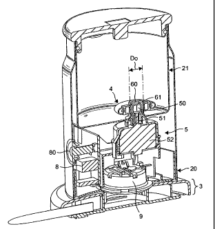
On the interior (INT) of the tank is positioned a
stirrer 4. Means 5 for driving the stirrer 4 are, for
their part, positioned on the exterior (EXT) of the
tank, preferably in the space between the tank and the
interior of the stand 20. The stirrer 4 and the drive
means 5 are positioned relative to one another in such
a way as to create forced stirring of the liquid inside
the tank without the use of an intrusive means crossing
the tank. To do that, the stirrer and its drive means
are of the magnetic type which means that the drive
means 5 produces a rotary magnetic field that drives
the stirrer, itself equipped with a means slaved to the
magnetic field. The magnetic means are positioned in an
offset manner with respect to the central axis "I" of
the tank so that the stirrer is made to rotate thus
circulating the liquid or froth in a way which is not
coaxial to the median central axis of the tank. In
fact, through such a configuration, the liquid and then
the froth tend to circulate more or less producing an
asymmetric cone more or less centred on the centre of
CA 02587258 2007-05-10
WO 2006/050900 PCT/EP2005/011921
- 17 -
the stirrer. This makes it possible to avoid the
formation of layers of constant speed which remain
circulating at the same radius and therefore do not mix
with one another. The layers by contrast do mix with
one another because, on the same radius, the layers are
circulating at different speeds; in particular, for a
given radius, the layers circulate at higher speeds on
the side where the stirrer is furthest from the edge of
the tank and at slower speeds on the side where the
stirrer is closest to the edge. This encourages all the
liquid or froth to circulate inside the tank, prevents
the stagnation of layers of liquid or froth and thus
reduces the areas where there is little or no stirring
taking place.
To guarantee controlled rotation of the stirrer in the
tank without the risk of the latter moving and
therefore avoiding loss of control of the magnetic
field, a means 6 for positioning the stirrer is
provided in the bottom 210 of the tank. The positioning
means is thus positioned eccentrically in the tank but
in relation to the position of the magnetic field so as
to allow the stirrer to be rotationally driven. In the
case illustrated, the positioning means 6 is a relief
formed in the wall of the tank and around which the
stirrer 4 is guided in rotation without excessive
friction. The positioning means could have other
configurations and could, for example, be a recess,
into which part of the stirrer is then inserted.
One advantage of a non-intrusive drive means is that it
is possible to construct a tank in which the liquid-
receiving part, and at least its bottom, comprises no
join line or discontinuous connection or line
demarcating orifices or the like able to create areas
which present a potential hygiene problem and/or areas
that are difficult to clean or rinse. Thus, the liquid-
receiving surface of the tank is preferably formed as
an integral piece. Within the meaning of the invention,
CA 02587258 2007-05-10
WO 2006/050900 PCT/EP2005/011921
- 18 -
welds forming a continuous seam between two elements
for example, are not considered to be joining lines or
discontinuous connections. By contrast, a joint using
screws, rivets or a nested fit is considered to be a
join or discontinuous connection liable to pose hygiene
problems. In particular, cleaning problems could arise
if food solid residue can become embedded and settle in
interstices of the join. The tank 21 consisting of its
raised surfaces 211 and its bottom 210, therefore forms
a surface for contact with the liquid that is
substantially smooth, with no areas encouraging
attachment of solid food matter such as protein or the
like. Such a tank can be made from a metal that is a
good conductor of heat such as stainless steel, copper
or aluminium. It may, for example, be moulded as a
single piece. In the construction illustrated in
Fig. 4, the tank 21 is connected to the edges 200 of
the stand 20 by its top edges 230 by any appropriate
connecting means such as welding, brazing, bonding or
clipping. The tank alone may also be mounted removably
with respect to the stand so that it can easily be
removed for cleaning in a dishwasher. The lid 22 is
connected to the tank as a tight fit via an engagement
edge 220 and a deformable elastomeric or plastic gasket
221. Other means for closing the lid 22 are possible,
such as screw-fastening or elastic clipping.
To drive the stirrer, the drive means 5 are~arranged to
produce a magnetic field passing through the
positioning means 6 which forms the relief 60 on the
interior (INT) of the tank. To do that, the drive means
5 comprises a magnetic drive portion 50 housed in the
part forming a recess or indentation 61 when viewed
from the exterior (EXT) of the tank. This magnetic
drive portion thus comprises one or several elements
500 made of ferromagnetic material. The magnetic drive
portion 50 is itself driven in direct rotation by a
drive spindle 51 connected to an electric motor 52
vertically aligned with the positioning means 6. In
CA 02587258 2007-05-10
WO 2006/050900 PCT/EP2005/011921
- 19 -
order to obtain advantageous results in terms of froth
production, the rotational speed of the stirrer is
controlled so that it reaches at least 1500
revolutions/min. As a preference, the speed is at least
1650 revolutions/min, and more preferably still,
between 1800 and 2500 rpm.
As shown by FIGs 5 and 6, the stirrer 4 according to
one embodiment of the invention has an annular overall
shape allowing it to fit freely around the relief-
forming positioning means. The relief preferably is in
the shape of a cylinder. The stirrer 4 is thus equipped
with a central slot 40 of a complementary shape and of
an inside diameter D slightly larger than the outside
diameter po of the external surface of the relief 60.
The diameters are thus determined one relative to the
other, so as to allow rotation without excessive
friction or, at least, with a minimum of friction,
while at the same time ensuring an effective magnetic
connection with the drive means. The stirrer comprises
at least one magnetically slaved portion which
possesses elements made of ferromagnetic material such
as a pair of magnets 41, 42 which are housed in a
plastic support 43 which may be injection-moulded
around the magnets or assembled in several parts 430,
431 by clipping, bonding or any other means. The
stirrer possesses an external or peripheral portion 44
which comprises the actual stirring elements proper. In
the embodiment depicted, these elements are formed by a
series of turns 45 of wire in the overall shape of a
torus. To prevent them from deforming, the turns 45 are
held in place by an internal annular reinforcing
element 46. When rotationally driven, such an element
produces rapid emulsification of the liquid,
particularly milk, especially when the frothing
temperatures are obtained at the same time.
However, other equivalent configurations of the
stirring elements may replace the one depicted. These
CA 02587258 2007-05-10
WO 2006/050900 PCT/EP2005/011921
- 20 -
may, for example, involve impellers, blades, gratings
or needles or yet others.
Thus, when the motor is electrically powered, its
spindle rotationally drives the magnetic drive portion
50 and this creates a rotary local magnetic field
collaborating with the magnets 41, 42 and this as a
result causes the stirrer to rotate about the relief.
The rotational speed of the stirrer is thus regulated
to the rotational speed of the motor spindle.
According to one aspect of the invention, heating means
are provided to heat the tank during stirring. Heating
facilitates the production of froth and considerably
reduces the stirring time. The froth is also preferably
served hot, particularly when intended for hot
beverages such as cappuccinos. To do that, in one
embodiment of the invention, means for direct heating
of the tank are provided. Direct-heating means are to
be understood as meaning means of the heating resistive
type or equivalent, electrically insulated but
thermally directly associated with the surface of the
tank.
In one embodiment of the invention, the direct-heating
means comprise a heating circuit of the "thick film"
type printed directly onto the external surface of the
tank, preferably onto the external surface of the
bottom of the tank. The advantage with this technology
is that it provides a good distribution of the power
transmitted to the tank (that is to say, therefore, a
greater density in watts per square centimetre). In
consequence, the liquid is prevented from sticking to
the surface of the tank while at the same time ensuring
excellent transmission of heat to the liquid.
FIG. 7 illustrates one example of a type of printed
heating circuit of this type. In one possible
embodiment, a circuit extends over just the bottom of
CA 02587258 2007-05-10
WO 2006/050900 PCT/EP2005/011921
- 21 -
the tank (for example, as in the embodiment of FIG. 7).
In another possible embodiment, a circuit extends over
the bottom and the side walls of the tank. In another
possible embodiment, several circuits are provided, at
least one of them being on the bottom, and at least one
on the sides of the tank.
The circuit 7 as depicted therefore comprises an
insulating layer 70 associated with the external
surface of the heated surface of the tank and a
resistive heating printed track 71 which, in use, faces
downwards. The track 71 is arranged in such a way as to
produce a total power of about 250 to 1200 watts,
preferably 400 watts applied to the heated surface. Its
mean electrical power density with respect to the
heated surface or circuit 7 is thus between 5 and 30
watts per cm2, preferably between 15 and 25 watts per
cm2. The track 71 preferably covers at least 40% of the
heated surface, and more preferably still covers more
than 50% thereof, so as to produce an adequate
distribution of the total power over the heated surface
thus preventing the milk from sticking and turning
brown on the internal surface of the tank. The mean
density is calculated using the formula: mean density =
total electrical power/total surface area (7).
Electrical contacts 72, 73, 74 are located at the ends
of the tracks to provide the electrical connections for
the circuit. According to one aspect of the invention,
the electrical contacts are three in number, associated
with three ends; thus, there is one contact 72
associated with neutral, one contact 73 associated with
live and finally a third contact 74 connected to the
low-voltage electric motor to power the latter at the
required voltage (for example: 8.2 volts in the example
shown). Such a configuration makes it possible to
dispense with a transformer for operating the motor and
therefore allows the cost and complexity of the system
to be reduced. In one possible embodiment, the printed
CA 02587258 2007-05-10
WO 2006/050900 PCT/EP2005/011921
- 22 -
heating circuit comprises an intermediate metal backing
plate separating the layer of insulation from the
bottom of the tank. In this case, the backing plate is
as thin as possible, preferably 1 mm thick or less. A
backing plate separate from the bottom may be needed in
an embodiment in which the tank is mounted removably
with respect to the stand. However, in an embodiment in'
which the tank is permanently mounted, the circuit is
preferably printed directly onto the tank.
Other technologies may replace a heating circuit of the
"thick film" type, for example shielded resistors.
However, this technology is less preferred because the
transmission of power is not over such a large surface
area (but is generally over a simple generatrix) and
requires an additional operation of brazing the
resistor directly against the surface of the tank. In
consequence, in order to transmit the same power, the
resistor has to be overheated and this creates areas
where the milk tends locally to stick to the surface of
the tank. Other heating means comprise induction
heating or infrared heating. These means may be
combined or employed in place of the resistive means.
In one embodiment of the invention, a temperature
sensor is provided to measure the temperature of the
tank. The sensor may be attached to the insulated
contact 75 of the "thick film" circuit 7, preferably
near the middle of the bottom of the tank. The sensor
may be of the NTC type connected to an electronic
controller 8. The sensor may also be a simple sensor of
the bimetallic strip type which is less precise and
less repeatable but does not require associated control
electronics. The contactors of the heating means are
themselves electrically connected to the controller 8
by blades, wires and/or other means. When the
temperature reaches a given set point temperature, the
controller cuts off the electrical supply circuit to
the heating means. The set point temperature is
CA 02587258 2007-05-10
WO 2006/050900 PCT/EP2005/011921
- 23 -
determined such that the liquid is heated to below its
boiling point, preferably in a temperature range that
is optimal for frothing the liquid. In the case of
milk, for example, the liquid temperature is brought to
a temperature of between 60 and 80 C in under 40
seconds, preferably between 65 and 75 C in about 30
seconds. Of course, the temperature rise dynamics are
partially dependent on factors such as the volume to be
heated and the initial temperature of the liquid.
The stand comprises an "on" button 80 that the user can
operate. When this button is pressed or activated by
any other means it jointly switches on the electrical
power supply to the heating means and the electrical
power supply to the electric motor for turning the
stirrer. Thus, the liquid is both directly heated and
stirred at the same time. A timer is associated to the
control means to automatically switch the electric
motor off. The running period of the electric motor is
programmed in the control means as a function of the
liquid to be frothed and its volume. For milk, the
running period is fixed within a range period of from
about 30 to 60 seconds. Preferably, the tank comprises
a fill mark to visually indicate to the user the amount
of liquid to be filled in the tank. The fill mark
correspond to a predetermined level of liquid to be
frothed and to programmed running period adapted to
deliver the optimum froth. For example, a volume of
about 50 ml of milk can thus be converted into a stable
froth at 75 C in under 30 seconds.
The cordless foaming unit 2 and the electrical base
unit 3 are connected by a collection 9 of general
connectors known as "cordless" connectors. A first
connector is connected to the central lower part of the
stand 20. The first connector is electrically connected
to the electrical elements and control elements of the
foaming unit, particularly the controller, the electric
motor and the heating means. A second connector of
CA 02587258 2007-05-10
WO 2006/050900 PCT/EP2005/011921
- 24 -
complementary shape is associated with the electrical
base unit which can be connected to the mains by the
electric lead.
The first connector 90 comprises electric terminals,
typically a neutral, a live and an earth,
concentrically arranged and which can collaborate with
electric sockets of the second connector 91. The first
and second connectors are configured in terms of their
shapes to collaborate in engagement with one another
simply by standing the foaming unit vertically (or more
or less vertically) on the electrical base unit so that
the electrical terminals (live, neutral, earth) of the
first connector 90 connect on contact with the
respective electrical sockets (live, neutral, earth) of
the second connector 91. An example of a collection of
connectors of this type which is known per se is
described in detail in patent US 5,971,810. The
advantage of such a system is that, in the application
of the invention, it allows the foaming unit to be
disconnected easily so that the froth can be served and
the tank can be cleaned. It also allows a tank to be
designed which is equipped with heating means directly
associated with the heating means, for better heating
efficiency and therefore a lower froth preparation
time. Other possible known types of cordless connector
may be used as equivalent means without departing from
the scope of the invention.
FIG. 8 depicts an embodiment in which the tank is
non-cylindrical with respect to the vertical axis I. In
this example, the tank 21 has an elongate shape with
two convex first sides 215, 216 and two second sides
217, 218, at 90 to the first sides, which are concave.
The stirrer 4 and the positioning means 6 will then be
positioned at the middle of the tank as illustrated or
alternatively may be offset from the middle. The shape
of the tank is such that it produces a disturbed
circulation of the liquid and the froth thus
CA 02587258 2007-05-10
WO 2006/050900 PCT/EP2005/011921
- 25 -
encouraging the rapid creation of froth and reducing
any possible remaining volume of liquid.
FIGs 9 and 10 illustrate another embodiment of the
invention, in which embodiment the tank 21 has walls
and/or obstacles extending as reliefs offset from the
median vertical axis I. In particular, in the example
illustrated, a plurality of protrusions 212 for
disturbing the circulation of fluid are present in the
bottom and likewise 213 on the sides of the tank. These
walls run more or less radially and along just some
portions of the tank. They are preferably offset to
encourage the fluid in the tank to flow in a sinuous
path. It goes without saying that numerous different
and equivalent arrangements are within the competence
of the person skilled in the art without thereby
departing from the scope of the invention.