Language selection

Search

Patent 2587313 Summary

Third-party information liability

Some of the information on this Web page has been provided by external sources. The Government of Canada is not responsible for the accuracy, reliability or currency of the information supplied by external sources. Users wishing to rely upon this information should consult directly with the source of the information. Content provided by external sources is not subject to official languages, privacy and accessibility requirements.

Claims and Abstract availability

Any discrepancies in the text and image of the Claims and Abstract are due to differing posting times. Text of the Claims and Abstract are posted:

  • At the time the application is open to public inspection;
  • At the time of issue of the patent (grant).
(12) Patent: (11) CA 2587313
(54) English Title: QUICK COUPLING
(54) French Title: RACCORD RAPIDE
Status: Granted
Bibliographic Data
(51) International Patent Classification (IPC):
  • F16L 37/22 (2006.01)
  • F16L 37/23 (2006.01)
(72) Inventors :
  • AROSIO, MASSIMO (Italy)
(73) Owners :
  • FASTER S.P.A. (Italy)
(71) Applicants :
  • FASTER S.P.A. (Italy)
(74) Agent: OSLER, HOSKIN & HARCOURT LLP
(74) Associate agent:
(45) Issued: 2015-02-24
(22) Filed Date: 2007-05-03
(41) Open to Public Inspection: 2007-11-03
Examination requested: 2012-04-11
Availability of licence: N/A
(25) Language of filing: English

Patent Cooperation Treaty (PCT): No

(30) Application Priority Data:
Application No. Country/Territory Date
MI2006A-000863 Italy 2006-05-03

Abstracts

English Abstract

A quick coupling comprises a male element (2) which can be threadably assembled to a female element (3), housing an inner tubular supporting body (8) in turn housing a bearing (11) thereon the female element (3) bears, the female element (3) including a plurality of radially extending holes (20) in which are engaged ball elements (21) which can be fitted in a circumferential slot formed in the male body (2) and being adapted to be radially locked by an enlarged portion (16) formed on an inner side of a ring nut which can be driven against an urging spring (17) pertaining to the female element.


French Abstract

Un raccord rapide comprend un élément mâle (2) qui peut être assemblé par filetage à un élément femelle (3), logeant un corps tubulaire interne de support (8) qui loge à son tour un palier (11) sur les supports de lélément femelle (3), lélément femelle (3) comportant une pluralité de trous (20) sétendant radialement dans lesquels sont engagés des éléments sphériques (21) qui peuvent être ajustés dans une fente circonférentielle formée dans le corps mâle (2) et qui est adapté pour être verrouillé radialement par une partie élargie (16) formée sur un côté intérieur dun écrou à illet, lequel peut être entraîné contre un ressort de sollicitation (17) se rattachant à lélément femelle.

Claims

Note: Claims are shown in the official language in which they were submitted.

7
The embodiments of the present invention for which an exclusive property or
privilege is
claimed are defined as follows:
1. A quick coupling, comprising a quick coupling male element comprising a
male body
having an outer thread and a circumferential slot, said male element can be
threadably
connected to a quick coupling female element comprising an outer tubular body
having an
inner thread, a ring nut having a circumferential enlarged portion, and a
counter biasing
spring, characterized in that said female element comprises an inner tubular
body housing a
bearing thereon said outer tubular body bears, and said outer tubular body
comprises, at a
front portion thereof, a plurality of circumferentially arranged holes, said
holes housing
therein a plurality of radially movable ball elements which can be engaged in
the
circumferential slot of the male body, and that said ball elements can be
radially locked by
the circumferential enlarged portion formed on an inner side of the ring nut
which can be
driven against the counter biasing spring.
2. A quick coupling, according to claim 1, characterized in that said
bearing is housed in
a chamber of said outer tubular body and is made as a thrust bearing.
3. A quick coupling, according to claim 2, characterized in that said
bearing is retrained
at an operating position thereof in said chamber by resilient ring elements
engaged in
circumferential slots.
4. A quick coupling, according to claim 1, characterized in that said
female element of
said quick coupling houses a displaceable ring nut having an annular
circumferential enlarged
portion there against the counter biasing spring bears, said spring abutting
in turn against an
outer shoulder of the outer tubular body.
5. A quick coupling, according to claim 4, characterized in that said
movable ring nut is
restrained at an end portion thereof by a resilient ring element.
6. A quick coupling, according to claim 1, characterized in that, with the
male body
being fully threaded in said outer tubular body of said quick coupling, said
ball elements are
engaged in the circumferential slot of said male body and said counter biasing
spring causes
said ring nut to be driven in a set direction, thereby locking said
circumferential enlarged
portion on said ball elements.

Description

Note: Descriptions are shown in the official language in which they were submitted.


CA 02587313 2007-05-03
1

QUICK COUPLING
BACKGROUND OF THE INVENTION

The present invention relates to a quick coupling providing a
safe connection of mechanical parts, an easy plug-in,
respectively plug-out, of the quick coupling components, an
efficient mutual connection and plug-in/plug-out, without using
operating tools.

A well known requirement of the prior art, in particular in the
electric or electronic apparatus refrigerating field, is that of
continuously refrigerating electric or electronic components
included in said apparatus.

This is usually performed by using a plurality of pipes
designed for supplying a refrigerating fluid to the devices to be
refrigerated, and return ducts for recovering the refrigerating
fluid.
Said delivery or feeding, respectively return, pipes or ducts,
are conventionally coupled to the devices to be refrigerated,
by means of quick-coupling assemblies.
In a prior quick coupling assembly, the male element thereof
has a male element thread which can be engaged with a
female element thread formed on the female part of the
coupling.

To prevent the two bodies of the quick coupling from
accidentally detaching and sliding away, said prior quick


CA 02587313 2007-05-03
2

couplings usually comprise a protective ring nut element which
can be clamped under a clamping torque applied by a torque
wrench.
A drawback of such a prior arrangement is that both the
connecting and disengaging operations of the threaded parts
require that a tool be used, such as a torque wrench.

Such a tool must also be used for overcoming the great friction
occurring, in particular, between an inner tubular element and
an outer tubular element of the quick coupling female part.
SUMMARY OF THE INVENTION

Thus, the object of the present invention is to provide a novel
quick coupling allowing the threaded bodies thereof to be
slidably connected, respectively disconnected, by simple
manual operations, without requiring operating tools, while
providing a safe connection of the quick coupling bodies.

According to the present invention, the above mentioned
object is achieved by a quick coupling comprising a male
element which can be threadably connected to a female body,
said female body including an inner tubular body housing a
bearing on which an outer tubular body bears.

Advantageously, the female body outer tubular body
comprises, at a front side thereof, a plurality of
circumferentially extending holes housing radially movable ball
elements therein, said ball elements being adapted to be
engaged in a circumferential slot of the male body, said ball


CA 02587313 2007-05-03
3

elements being adapted to be radially locked by a
circumferential enlarged portion formed on the inner side of a
female body ring nut and adapted to be driven against a
counter-biasing spring.

BRIEF DESCRIPTION OF THE DRAWINGS

The subject matter of the present invention will be disclosed
and illustrated in a more detailed manner hereinafter with
reference to an exemplary embodiment thereof, which is
shown in the accompanying drawings, where:

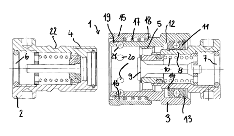
Figure 1 is a longitudinal cross-sectional view showing the
male element and female element of a quick coupling in a
disassembled condition thereof;

Figure 2 is a further longitudinal cross-sectional view showing
the components of the quick coupling in a partially threaded
assembled condition; and
Figure 3 shows the components of the quick coupling in a fully
assembled condition.

DESCRIPTION OF THE PREFERRED
EMBODIMENT
As shown in figure 1, the quick coupling, generally indicated
by the reference number 1, comprises a quick coupling male
element 2 and a quick coupling female element 3 which can
be mutually coupled to one another.
To provide a threaded type of connection, the male element 2
comprises, at a front portion thereof, an outer thread 4, to be


CA 02587313 2007-05-03
4

coupled with an inner thread 5 formed inside the female body
or element 3.

The operating fluid, such as a refrigerating fluid, is supplied, in
a per se known manner, either through the inlet 6 of the male
body 2 or through the inlet 7 of the female element 3.

The inlet 7 is formed in a tubular body 8 housing a
longitudinally extending stem 9 encompassed by a spring 10,
as known in the prior art.

The constructional elements 9 and 10, and related gaskets,
advantageously 0-ring seals, will be not disclosed in further
details therein, since they are well known in the prior art and
are conventionally used in prior quick couplings.

Advantageously, the tubular body 8 houses therein a bearing
11, advantageously a thrust bearing, designed for resisting
both against axial pushing forces and against radial efforts.
More specifically, the bearing 11 is housed in an annular
chamber 12 formed in the outer tubular body 3 forming the
female part of the quick coupling.

Also advantageously, the bearing 11 is held in its desired
position by resilient ring elements 13 and 14, engaged in
suitable engaging slots; in this connection it should be
apparent that it would be also possible to provide other
locating and locking means for properly locating and locking
the bearing.

Thus, owing to the provision of the bearing 11, any friction


CA 02587313 2007-05-03

forces between the outer body 3 and inner tubular body 8 of
the female element will be practically eliminated, thereby
allowing the connection, respectively disconnection, of the
threaded parts 4 and 5 to be manually carried out, in a very
easy manner and without using operating tools, since any
friction forces, as operating in prior couplings, are herein
overcome, owing to the provision of said bearing 11.

The front side or portion of the female body 3 of the quick
coupling 1 receives herein a movable ring-nut element 15
having, on a front side thereof, an inner annular enlarged
portion 16 there against abuts a spring 17 which also abuts
against an outer shoulder 18, positionally fixed, of the tubular
body 3.
At the front portion thereof, said ring nut 15 is held at an end
position by a resilient ring element 19.

A plurality of radially extending holes 20 are circumferentially
formed in the front portion of the tubular body 3, said holes
receiving therein a corresponding plurality of ball elements 21
which, in a fully assembled condition of the male body 2 and
female body 3, are engaged in a circumferential groove 22 of
the male body 2, and operate as locking means as they are
engaged in the circumferential groove 22 upon connecting the
bodies 2 and 3.

Upon threading the body 2, by the threads 4 and 5, in the
female body 3, said ball elements 21 will be radially outward


CA 02587313 2007-05-03
6

displaced from the male body 2 and, accordingly, will cause
the ring nut 15 to be backward driven (figure 2), thereby
pressing the spring 17.

With the body 2 fully threaded in the tubular body 3 of the
quick coupling, generally indicated by the reference number 1,
the ball elements 21 will enter the groove or slot 22 of the
male body 2 thereby causing the spring 17 to drive the ring nut
15 in the direction shown by the arrow (f) in figure 3, thereby
the inner radially extending enlarged portion 16 will be
arranged above the ball elements 21 to in turn lock the latter at
their desired positions thereby providing a safe and properly
locked connection between the body 2 and body 3 of the quick
coupling 1.

As is desired to disconnect the body 2 from the body 3, the
ring nut 15 must be displaced in the direction indicated by the
arrow (g) in figure 3, to allow the ball elements 21, which are
now in a free condition, to be radially displaced, to withdraw
the body 2 from the tubular body 3, since the ball elements 21
will be able of freely radially outward moving, to allow the body
2 to be easily disengaged.

Representative Drawing
A single figure which represents the drawing illustrating the invention.
Administrative Status

For a clearer understanding of the status of the application/patent presented on this page, the site Disclaimer , as well as the definitions for Patent , Administrative Status , Maintenance Fee  and Payment History  should be consulted.

Administrative Status

Title Date
Forecasted Issue Date 2015-02-24
(22) Filed 2007-05-03
(41) Open to Public Inspection 2007-11-03
Examination Requested 2012-04-11
(45) Issued 2015-02-24

Abandonment History

There is no abandonment history.

Maintenance Fee

Last Payment of $458.08 was received on 2022-04-13


 Upcoming maintenance fee amounts

Description Date Amount
Next Payment if small entity fee 2023-05-03 $253.00
Next Payment if standard fee 2023-05-03 $624.00

Note : If the full payment has not been received on or before the date indicated, a further fee may be required which may be one of the following

  • the reinstatement fee;
  • the late payment fee; or
  • additional fee to reverse deemed expiry.

Patent fees are adjusted on the 1st of January every year. The amounts above are the current amounts if received by December 31 of the current year.
Please refer to the CIPO Patent Fees web page to see all current fee amounts.

Payment History

Fee Type Anniversary Year Due Date Amount Paid Paid Date
Application Fee $400.00 2007-05-03
Registration of a document - section 124 $100.00 2008-02-01
Maintenance Fee - Application - New Act 2 2009-05-04 $100.00 2009-05-04
Maintenance Fee - Application - New Act 3 2010-05-03 $100.00 2010-05-03
Registration of a document - section 124 $100.00 2010-08-13
Maintenance Fee - Application - New Act 4 2011-05-03 $100.00 2011-04-21
Request for Examination $800.00 2012-04-11
Maintenance Fee - Application - New Act 5 2012-05-03 $200.00 2012-05-03
Maintenance Fee - Application - New Act 6 2013-05-03 $200.00 2013-04-22
Maintenance Fee - Application - New Act 7 2014-05-05 $200.00 2014-05-05
Final Fee $300.00 2014-12-09
Maintenance Fee - Patent - New Act 8 2015-05-04 $200.00 2015-04-24
Maintenance Fee - Patent - New Act 9 2016-05-03 $200.00 2016-04-13
Maintenance Fee - Patent - New Act 10 2017-05-03 $250.00 2017-04-12
Maintenance Fee - Patent - New Act 11 2018-05-03 $250.00 2018-04-11
Maintenance Fee - Patent - New Act 12 2019-05-03 $250.00 2019-04-10
Maintenance Fee - Patent - New Act 13 2020-05-04 $250.00 2020-04-23
Maintenance Fee - Patent - New Act 14 2021-05-03 $255.00 2021-04-14
Maintenance Fee - Patent - New Act 15 2022-05-03 $458.08 2022-04-13
Owners on Record

Note: Records showing the ownership history in alphabetical order.

Current Owners on Record
FASTER S.P.A.
Past Owners on Record
AROSIO, MASSIMO
FASTER INTERNATIONAL S.R.L.
FASTER S.P.A.
NUOVA FASTER S.P.A.
Past Owners that do not appear in the "Owners on Record" listing will appear in other documentation within the application.
Documents

To view selected files, please enter reCAPTCHA code :


To view images, click a link in the Document Description column. To download the documents, select one or more checkboxes in the first column and then click the "Download Selected in PDF format (Zip Archive)" or the "Download Selected as Single PDF" button.

List of published and non-published patent-specific documents on the CPD .

If you have any difficulty accessing content, you can call the Client Service Centre at 1-866-997-1936 or send them an e-mail at CIPO Client Service Centre.


Document
Description 
Date
(yyyy-mm-dd) 
Number of pages   Size of Image (KB) 
Abstract 2007-05-03 1 17
Description 2007-05-03 6 210
Claims 2007-05-03 2 57
Drawings 2007-05-03 3 144
Representative Drawing 2007-10-09 1 24
Cover Page 2007-10-26 1 51
Claims 2014-04-17 1 52
Representative Drawing 2015-02-04 1 23
Cover Page 2015-02-04 1 49
Correspondence 2007-05-31 1 25
Assignment 2007-05-03 3 86
Assignment 2008-02-01 3 85
Fees 2009-05-04 1 41
Fees 2010-05-03 1 42
Assignment 2010-09-09 3 91
Assignment 2010-08-13 27 1,232
Fees 2011-04-21 1 41
Prosecution-Amendment 2014-04-17 8 322
Prosecution-Amendment 2012-04-11 1 39
Fees 2012-05-03 1 40
Fees 2013-04-22 1 43
Prosecution-Amendment 2013-10-18 3 96
Fees 2014-05-05 1 41
Correspondence 2014-12-09 1 42