Note: Descriptions are shown in the official language in which they were submitted.
CA 02587668 2013-04-11
BRAKING CONTROL APPARATUS AND BRAKING CONTROL METHOD FOR
ELECTRIC VEHICLE
Technical Field
[0001]
This invention relates to a braking control apparatus
and braking control method for an electric vehicle that uses
an electric brake based on an electric motor in combination
with a mechanical brake such as air brake.
Background Art
[00-02]
In an electric vehicle that uses an electric brake based
on an electric motor in combination with a mechanical brake
such as air brake, a braking system is generally used in which
the electric brake is preferentially used when braking and the
insufficient electric braking force to realize the braking
force of the whole vehicle is supplemented by the mechanical
braking. However, the electric brake based on the electric
motor and the mechanical brake such as air brake differ in the
response speed to a braking command. Therefore, particularly
when starting braking, in order not to lower the
comfortableness in riding, the electric braking force is
outputted virtually and the action of the mechanical brake is
restrained to prevent excessive braking forces. Thus, braking
is started smoothly. (See, for example, JP-A-6-253407
(Patent Reference 1 (Fig 1) ) .
1
CA 02587668 2007-05-15
Disclosure of the Invention
Problems that the Invention is to Solve
[0004]
However, in the conventional braking control apparatus
for an electric vehicle, the virtual braking force outputted
at the time of starting braking is not outputted in accordance
with the actual electric braking force, that is, the
regenerative braking force. Therefore, in the case where
there is no regenerative load, a dead time from the start of
braking to the start of actual braking occurs. There is a
problem that in spite of the driver's operating the brake in
the electric vehicle, an idle running time occurs, during which
braking of the vehicle does not work.
[0005]
This invention is made in order to solve the problem as
described above. It is an object of this invention to provide
a braking control apparatus and braking control method for an
electric vehicle that changes the magnitude of a virtual
braking force if a regenerative load is small when starting
braking so that there is little response delay to a braking
force command from the driver's seat even in a state where the
regenerative load is small.
Means for Solving the Problems
2
CA 02587668 2012-10-15
[0006]
According to this invention, a braking control
apparatus for an electric vehicle in which an AC motor is
driven by a power converter fed with a DC wiring voltage,
the power converter is controlled in accordance with a
braking command from a driver's seat to actuate an electric
brake based on the AC motor, and a lacking part of the
electric braking force is supplemented by a mechanical
brake, includes a braking device that calculates an electric
braking force command in accordance with the braking command
and generates a mechanical braking command, and a control
circuit that calculates an electric braking force on the
basis of the electric braking command from the braking
device and the braking force command and controls the power
converter. The control circuit includes a control
calculating unit that calculates the electric braking force
and controls the power converter, a virtual braking force
calculating unit that calculates a virtual braking force to
complement the electric braking force when starting braking,
on the basis of the braking command and an output of a
voltage sensor for detecting an input voltage to the power
converter, and an adder that adds a calculation output of
the control calculating unit and a calculation output of the
virtual braking force calculating unit. The
mechanical
braking command from the braking device is changed in
accordance with an output of the adder.
[0007]
3
CA 02587668 2012-10-15
Also, according to this invention, a braking control
method for an electric vehicle in which an AC motor is driven
by a power converter fed with a DC wiring voltage, the power
converter is controlled in accordance with a braking command
from a driver's seat to actuate a regenerative brake based on
the AC motor, and a lacking part of the electric braking
force is supplemented by a mechanical brake, includes
calculating a virtual braking force to complement the
regenerative braking force when starting braking, changing
the virtual braking force to reduce response delay to the
braking command if a regenerative load is small, and changing
the mechanical braking command along with the change in the
virtual braking force.
Advantage of the Invention
[0008]
According to this invention, in the electric vehicle
that uses the electric brake in combination with the
mechanical brake, when starting braking, braking control can
be made with little response delay to the braking command
from the driver's seat even in the state where the
regenerative load is small.
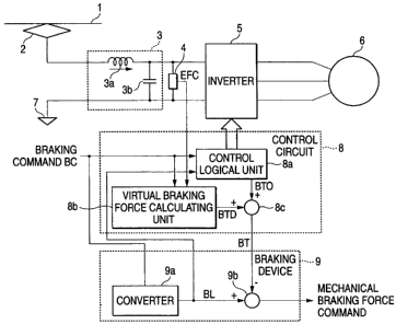
Fig. 1 is a structural block diagram showing a control
apparatus for an electric vehicle according to Embodiment 1
of this invention.
Fig. 2 is a waveform view of each part for explaining a
first operation at the time braking in Fig. 1.
Fig. 3 is a waveform view of each part for explaining a
second operation at the time braking in Fig. 1.
4
CA 02587668 2007-05-15
Fig. 4 is a waveform view of each part for explaining
a third operation at the time braking in Fig. 1.
Fig. 5 is a block diagram showing a schematic
structure of a virtual braking force calculating unit shown
in Fig. 1.
Best Mode for Carrying Out the Invention
[0009]
Embodiment 1
Fig. 1 is a structural view showing the relation between
a braking control apparatus for an electric vehicle and an AC
motor according to Embodiment 1 of this invention. In Fig.
4a
CA 02587668 2007-05-15
1, a DC voltage is inputted to an inverter 5, which is a power
converter, from a wiring 1 via a current collector 2 and a filter
circuit 3. In the filter circuit 3, 3a represents a reactor
and 3b represents a filter capacitor. 7 represents ground
potential.
A voltage sensor 4 is installed between the inverter 5
and the filter circuit 3. The voltage sensor 4 detects the
voltage on the DC side of the inverter, that is, filter
capacitor voltage, and outputs it to a control circuit 8. The
inverter 5 converts DC power to AC power, or AC power to DC
power, in accordance with a signal from the control circuit
8, and supplies an AC voltage to an AC motor 6, which is an
induction motor or the like.
Here, as the inverter 5, a power converter formed by a
semiconductor device and the like and controlled by, for
example, the PWM (Pulse Width Modulation) control mode, may
be used. These power converters output a pulse voltage under
the PWM control and convert a DC voltage to an AC voltage having
desired voltage amplitude and frequency.
In the control circuit 8, a control logical unit 8a
outputs a switching signal to the semiconductor device forming
the inverter 5 so that the inverter 5 is PWM-controlled in
accordance with a braking command BC from a driver' s seat and
an electric braking force command BL from a braking device 9.
The control logical unit 8a also calculates a braking
CA 02587668 2007-05-15
force equivalent to the actual generation torque of the AC motor
6, for example, from the motor current (not shown), or detects
the braking force of the motor from a brake torque sensor (not
shown) , and outputs a first braking force BTO to an adder 8c.
Moreover, a virtual braking force calculating unit 8b
in the control circuit 8 generates a braking force dummy signal
BTD for generating a virtual braking force to complement the
electric braking force, from the braking command BC and the
filter capacitor voltage inputted from the voltage sensor 4,
and outputs it to the adder 8c. The adder 8c adds the first
braking force BTO and the braking force dummy signal BTD and
outputs the result as a second braking force ET to the braking
device 9.
The braking device 9 calculates an electric braking force
command BL from the braking command by using a table preset
in a converter 9a and outputs the result to the control circuit
8 and a subtractor 9b. The subtractor 9b subtracts the second
braking force BT from the electric braking force command BL
and outputs the result as a mechanical braking command.
[0010]
Next, the operation of the braking control apparatus for
the electric vehicle of Fig. 1 with reference to Figs. 2 to
4.
To further clarify the advantage of the invention, first,
a case where there is a regenerative load and the electric brake
6
CA 02587668 2007-05-15
functions sufficiently when braking will be described with
reference to Fig. 2.
In the control circuit 8, the control logical unit 8a
controls the inverter 5 so that the electric brake acts in
accordance with the braking command BC from the driver' s seat
(Fig. 2b) and the electric braking force command BL from the
braking device 9 (Fig. 2c) . Moreover, a braking force
equivalent to the actual generation torque of the motor is
outputted as the first braking force BTO (Fig. 2d) . In the
control circuit 8, a delay time from the reception of the
braking command BC to the actual action of the electric brake
(section A) occurs because of the preparation for operating
the inverter, and a jerk (section B) is provided for smoothly
starting up the electric brake in order not to lower the
comfortableness in riding.
In the case where there is a sufficient regenerative load,
the filter capacitor voltage (Fig. 2a) does not rise and the
electric braking force rises up as commanded. Therefore, the
braking force BTO of the motor rises up as shown in Fig. 2d.
Moreover, in order to avoid overlap of the electric brake and
the mechanical brake when starting braking, the braking force
dummy signal BTD, which is a virtual braking force, is outputted
as shown in Fig. 2e. As a result, the adder 8c adds the braking
force BTO of the motor and the braking force dummy signal BTD
and outputs the second braking force BT to the braking device,
7
CA 02587668 2007-05-15
as shown in Fig. 2f. While the braking force dummy signal BTD
is provided stepwise here, a ramp function or the like may be
used.
On the other hand, in the braking device 9, when the
braking command BC is inputted, since the second braking force
BT remains zero during the action delay of the electric brake,
the subtractor 9b calculates the insufficiency of the second
braking force BT to realize the electric" braking force command
BL and outputs the complementary amount as a mechanical braking
force command. Generally, an air brake is used as the
mechanical brake and it has response delay because of its
characteristics. Therefore, the actual braking force
increases as shown in Fig. 2g.
When starting braking, as a result of the above-described
action, the braking force of the vehicle changes as shown in
Fig. 2h and smooth start of braking can be realized without
lowering the comfortableness in riding.
[0011]
Next, a case where there is no regenerative load at the
time of braking will be described with reference to Fig. 3.
In the case where there is no regenerative load, when
the electric brake is started up, the filter capacitor voltage
increases, as shown in Fig. 3a. Since the semiconductor device
forming the inverter 5 may be damaged if the filter capacitor
voltage continues to increase, the control circuit 8 limits
8
CA 02587668 2012-10-15
the electric braking force when the filter capacitor voltage
reaches a preset value or higher. As a result, even in the
case where the braking command BC exists as in Fig. 2, the first
braking force BTO equivalent to the electric braking force is
throttled down to zero when the filter capacitor voltage
reaches the preset value or higher, as shown in Fig. 3d. In
such a case, if virtual braking force calculating unit 8b
outputs the braking force dummy signal BTD as in Fig. 2, the
electric braking force is throttled down. Therefore, the
degree of deceleration of the vehicle is lowered at point C,
as shown in Fig. 3h. Then, at point D where the braking force
dummy signal BTD becomes zero, the first braking force BTO
equivalent to the electric braking force is zero. Since the
second braking force BT becomes zero, too, the second braking
force BT is insufficient for the electric braking command BL,
and the mechanical brake rises up at point D in order to
supplement the lacking part of the electric braking force.
As described above, since the mechanical brake has response
delay because of its characteristics, the mechanical braking
changes as shown in Fig. 3g (section E). Therefore, the -
braking force of the vehicle, that is, degree of
deceleration, is as indicated by the solid line in Fig. 3h
and the part equivalent to the broken line in Fig. 3h is
actually a non-braking state. Thus, there is a problem that
in spite of the driver's operating the brake, braking does
not work.
9
CA 02587668 2012-10-15
[0012]
Thus, to solve the problem as shown in Fig. 3 even in
the state where there is no regenerative load, the filter
capacitor voltage is detected by the voltage sensor 4 and the
braking force dummy signal BTD is calculated in accordance with
the filter capacitor voltage. The operation in this case will
be described with reference to Fig. 4.
In the case where there is no regenerative load, when
the electric brake is started up, the filter capacitor voltage
increases, as in Fig. 3. The virtual braking force calculating
unit 8b monitors the filter capacitor voltage EFC as shown in
Fig. 5. After the braking command BC is inputted, for example,
the filter capacitor voltage is calculated, and if the rate
of change in the voltage exceeds a preset value, it is judged
that there is no regenerative load (comparator output C is H)
by using a rate-of-change calculator 8b1 and a comparator 8b2.
The braking force dummy signal BTD is reduced to zero as shown
in Fig. 4e via a one-shot signal generator 8b3. As a result,
the second braking force BT changes as shown in Fig. 4f.
Therefore, the braking device judges that the second braking
force BT is insufficient for the electric braking command BL
at point F, and starts up the mechanical brake at point F in
order to supplement the lacking part of the electric braking
force.
As a result, the braking force of the vehicle, that is,
degree of deceleration, is as shown in Fig. 4h. The state that
CA 02587668 2007-05-15
the degree of deceleration becomes insufficient and the
non-braking exists as shown in Fig. 3 is resolved. The degree
of deceleration as operated by the driver is provided for the
vehicle.
[0013]
As described above, according to Embodiment 1, a braking
control apparatus and braking control method for an electric
vehicle can be realized in which the magnitude of the virtual
braking force is changed if a regenerative load is small when
starting braking so that there is little response delay to a
braking force command from the driver' s seat even in the state
where the regenerative load is small.
11
CA 02587668 2007-05-15
Description of Reference Numerals and Signs
[0015]
1 wiring, 2 current collector, 3 filter circuit, 3a
filter reactor, 3b filter capacitor, 4 voltage sensor, 5
inverter, 6 AC motor, 7 ground potential, 8 control circuit,
8a control logical unit, 8b virtual braking force calculating
unit, 8c adder, 9 braking device, 9a converter, 9b subtractor
12