Note: Descriptions are shown in the official language in which they were submitted.
CA 02587984 2007-05-08
METHOD AND APPARATUS FOR CORRECTING
MAGNETIC FLUX SENSOR SIGNALS
FIELD OF THE INVENTION
The present invention relates to techniques for detecting defects in
metallic string, and more particuierly in production tubulars and sucker rod
strings when pulled from a production well. The technique particularly relates
to
utilizing magnetic flux sensors to detect defects, and to correcting signals
from
magnetic flux sensors at a well site to better determine the nature and extent
of
the defect.
BACKGROUND OF THE INVENTION
Most sensors directly measuie the physical property of interest. Magnetic
sensors, however, detect changes or disturbances in magnetic fields that have
been created or modified. From those changes or disturbances, one can derive
information on properties, such as direction, presence, rotation, or
electrical
currents. Earth's field or medium-field sensors have a magnetic range which is
the earth's magnetic field to detennine compass headings for navigation.
Medium-field sensors indude a flux-gate magnetometer, and anisotropic
magneto-resistive (AMR). a Reed switch, sensors which use N-type silicone or
Ga A, and Giant Magneto Resistive (GMR) devices. GMR sensors may sense
the magnetic field strength over a wide range of fields. Since the GMR is able
to
detect the magnetic field rather than the change in magnetic field, they are
useful
as AC field sensors.
C:\CLIENT_kpm\RSM1276\276-applicatlon.doc - ~ ~
CA 02587984 2007-05-08
Various types of sensors have been used for detecting defects in oilfield
tubulars, including production tubing, casing, and sucker rod strings which
reciprocate or rotate to drive a downhole pump. The purpose of many of these
sensors is to determine the presence and magnitude of defects in the tubing or
sucker rod strings, so that joints with such defects can be replaced, and
furkher
measures taken to reduce the number and severity of the defects.
The output of a magnetic flux sensor, when used in an induced magnetic
field to perform detection or evaluation of flaws in a ferro-magnetic object,
is
inversely proportional to the square of the distance from the surface of the
object. In performing flaw detection and evaluation, the surface of the object
under examination is often subject to movement relative to the sensor such as
that incurred from irregular object shape or geometry, lack of centralization.
surface roughness, or other factors which may change the surface-to-sensor
distance. Conditions that result in an irregular shape or geometry of an
object.
lack of centralization, and surface roughness are commonly encountered when
detecting defects in oilfield tubular goods, parkicularfy when such defects
are
deterrnined at the well site. If the relative stand-off of the production
string or
sucker rod string changes, a random source of sensor amplitude error will be
introduced into all magnetic flux measurements.
This relative movement between the object being analyzed and the
magnetic flux sensor significantly complicates the determination of the
relative
importance of flaws detected with said sensors, since the signals may be a
result
C:ICLIENT kpi11\R&M12761276-appllcetlon.do0 - 2 -
CA 02587984 2007-05-08
of both relative flaw severity as well as the distance from the sensor to the
surface of the object under examination.
The disadvantages of the prior art are overcome by the present invention,
and an improved method and apparatus is hereinafter disclosed for correcting
signals from magnetic flux sensors at the well site when sensing oilfieid
tubular
defects.
C:ICUENT kpm1R&M1278\276-applicatlon.doc - 3 -
CA 02587984 2007-05-08
SUMMARY OF THE INVENTION
In one embodiment, an apparatus for detecting defects in an oilfield
tubular string at a well site as the string is pulled from a well comprises a
plurality
of magnetic flux sensors circumferentially spaced about the string at the weli
site,
and a plurality of laser stand-off sensors for determining changes in a stand-
off
distance between the one or more magnetic flux sensors and an external surface
of the string. A computer is used for correcting signals from a plurality of
magnetic flux sensors is a function of the detected stand-off distance.
According to one embodiment of a method of the invention, defects in
ofifleld tubular strings are determined at a well site as a string is pulled
from the
well. Defects are sensed with a plurality of magnetic flux sensors
circumferentially spaced. about the string at the well site. Changes in the
stand-
off distance between the one or more magnetic flux sensors and an external
surface of the string are also detected. A computer may be used for processing
signals from a plurality of magnetic flux sensors as a function of the
detected
stand-off distance.
These and furthev features and advantages of the present invention will
become apparent from the followirtg detailed description, wherein reference is
made to the figures in the accompanying drawings.
c:~Cl.tENT kpm\kt&M12761276-appqcatbn.doc - 4 -
CA 02587984 2007-05-08
BRIEF DESCRIPTION OF THE DRAWINGS
Figure 1 is a simplified view of a tubular string at a well site, with a
plurality
of upper magnetic sensors, a plurality of intermediate magnetic sensors, and a
plurality of lower laser stand-off sensors for collectively measuring defects
in the
string and correcting defect signals as a function of a detected send-off
distance.
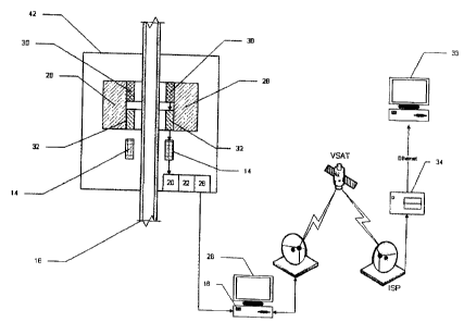
Figure 2 is a schematic view of the intermediate and lower sensors
positioned about a string, and the related hardware between the sensors and
the
computer,
Figure 3 is a block diagram of the data collection and distribution system
according to the Invention.
Figure 4 is a block diagram of a suitable laser triangulation sensor.
C:\CIIENT kprn1R&M12761278-appUcatlon.doc - 5 -
CA 02587984 2007-05-08
DETAILED DESCRIPTION OF PREFERRED EMBODIMENTS
Figure 1 illustrates one embodiment of the invention being used to detect
defects in the production tubing string 16 as it is pulled from a well, and
specifically through the top of wellhead 40 commonly provided at the surface
of
the well. The system of the present invention is thus able to detect defects
in
both the production tubing string and the sucker rod string, and to display
the
detected defects in real time to an operator at a well site as the string is
pulled
from the well. Those skilled in the art will appreciate that the magnetic flux
sensors 12 as disclosed herein may also be used for detecting defects in other
elongate, metallic oilfield strings as they are pulled from the well site,
including
lengths of coiled tubing and larger diameter fiubulars, such as casing. In a
suitable embodiment, the magnetic flux sensor 12 may include a magnetic coil
28, a Hall Effect device 30, or a Giant Magneto-Resistor device 32, as shown
in
Figure 3. The correction calculation may be performed using a computer 18,
which may also process the output of sensors 12.
According to a preferred embodiment, a plurality of laser triangulation
sensors 14 are used to measure the stand-off distance between the magnetic
flux sensors circumferentially spaced about a string pulled from a well and
the
surface of the string being examined for flaws. More particularly, the spacing
between the outer surface of the string and the sensors 14 is determined, and
this spacing is the same as the spacing between the sensors 12 and 13 and the
string due to the mounting of the sensor arrays. Even if this spacing is not
the
C;\CLIENT_kpm\R&M12761276-appllcation.doc - 6 -
CA 02587984 2007-05-08
same between the string and sensor 12, 13, and 14, the spacing relationship is
known and a corrective factor made by the computer.
A suitable laser triangulation sensor 14 may employ a CCD array 24,
image dispersion optics 25, and signal processing algorithms. After
determining
the stand-off distance, a calculation is performed to correct the output of
the
magnetic flux sensor, as compared to the normalized output of other similar
sensors, in computing the relative signal output. The output correction may be
in
the form of stand off based amplitude correction.
For examining a string coming out of a wefl, such as a tubing string or a
sucker rod string, a plurality of circumferential stand-off sensors 14
displaced
equally about the test article may be employed to Compare and correct the
output of the magnetic sensors as a function of the measured stand-off
distance.
A suitable laser sensor for this application is a laser triangulation sensor,
such as
the ACCU RANGE 200 laser displacement sensor supplied by Schmitt
Measurement Systems, Inc. This sensor projects a beam of visible light that
creates a spot on the target surface. Reflective light from the surface is
viewed
by a camera inside the sensor. The distance to the target is computed from the
distance of the center of the spot to the incident laser beam.
Figure 1 depicts a sensor array or package 42 for CSA flaw detection, for
detecting splits and holes, and for diameter/stand-off centralization
detection.
Each of the upper sensors 12 (in the array 42) may include a radial and an
axial
Hall Effect sensor, with the sensors arranged uniformly circumferentially
about
the production tubing 16. Figure 1 also depicts intermediate sensors 13, which
C:~CUENT kpm1R&Mk27W7$-appllcatlon.doc - 7 -
CA 02587984 2007-05-08
may be radial Hall Effect or GMR sensors. These sensors 13 primariiy detect
splits or holes in the tubular 16. This intermediate set of sensors may
include
boards having a single GMR or HE device sensitive to radial flux leakage from
the tubing under test. The lowermost group of sensors include a plurality of
opposing laser triangulation sensors 14 for stand-off and centralization
detection.
All of these sensors may be provided on a sleeve which surrounds the
production tubing 16, although the production tubing string is not necessarily
centered within the sleeve.
Figure 2 depicts a plurality of magnetic flux sensors 12 circumferentially
spaced about the production tubing or sucker rod 16. Offset sensors 14 are
similarly positioned about the tubing or rod string 16. Signals from each of
these
sensors, correlated as a function of the circumferential position of the
sensor and
the depth of the string being analyzed, are forwarded to the computer 18. A
synchronous multi-channel analog to digital converter 20 supplies information
to
the data acquisition and memory storage device 22. Also input to the
triggering
and storage device 22 are signals from a rotary depth encoder 24, which
provides the. depth synchronized ADC trigger by generating N pulses/foot of
string extracted from the well. Depth resolution can be configured by the type
of
rotary depth encoder utilized. Digitized MFL, stand-off, and depth signals are
temporarily stored in a memory buffer in device 22 then transferred by direct
memory access to controller 28. The real time controller 28, then transfers
the
buffered signals to computer 18, Computer 18 'may also accept configuration
commands through the hardware as shown in Figure 2 which may be transferred
C:\CIIENT_kpm\R&M1278\278-applfcatlon.doc - a -
CA 02587984 2007-05-08
back to the controller 28, trigger 22, or ADC 20 and sensors 12, 14, thereby
instructing the sensors to take particular measurements at certain depths or
at
certain points in time.
The transfer to the host computer 18 may be over a high speed ethernet
connection. The pulses from the rotary depth encoder 24 may be also used to
calculate synchronized depth in the controller 28, as MFL and stand-off
information are captured, optionally using the work-over rig cabling to lift
the
string from the well.
Figure 3 illustrates a block diagram of a system according to the present
invention for reliably detecting defects in a tubular string, including the
sensors
12, 13, and 14 discussed above. The information from each of these sensors
arrays may be input to computer 18, where the information from the upper and
intermediate sensors may be collected and correlated with the detected stand-
off
distance from the lower sensors, Data from each sensor may be correlated to
the depth of the string in the well being examined, and also the
circumferential
position of each sensor about the string. Display 26 is provided for
outputting a
collective signat from the 'magnetic flux sensors. Signals for the computer 18
at
the well site may be transferred by various telemetry systems to computer 33
at
an office remote from the well site, and aiso to. central storage computer 34
for
data storage, so that the signals can be later compared to other wells or
signals
from the string subsequently pulled from the same well. Display 26 or another
display may also be used for outputting a signal from the stand-off sensors
and
C:\GJEN7_xpm1R&M127M78-aDOIoa0on.doc - 9 -
CA 02587984 2007-05-08
thus displaying the stand-off between the magnetic flux sensors and the
external
surface of the string.
Figure 4 simpfistically depicts a suitable laser triangulation sensor which
may be used according to the present invention to determine the axial spacing
or
standoff between the sensors and the outer surface of the rod or tubing being
monitored. The laser transmits as incident beam to the exterior surface of
tubing
16, and the reflected beam passes through image dispersion optics 25 to result
in the spot on the surface of the CCD array 24. No sensor hardware contact
with
the item being sensed is required. The laser triangulation sensors are able to
reliably determine the standoff between each of the sensors circumferentially
positioned around the tubular. Out of roundness or wear on a portion of the
external surface may be detected, and information from all the sensors may be
used to calculate the effective cross-sectional area and effective outer
surface
diameter of the string being monitored.
Using a non-contact sensor to measure stand-off has significant
advantages compared to other techniques for correcting signals from magnetic
flux sensors while at the well site in order to compensate for a varying stand-
off
between circumferentially spaced sensors and the string. Sensors which engage
the string Inherently engage couplings and connectors on the string, which
impart
shock, vibration, and damage to the sensors. Moreover, sensors intended for
engagement with the string may engage a mud layer or paraffin layer on the
extemal surface of the string, thereby producing erroneous correction signals.
A
transmitted beam sensor may distinguish between a metallic external surface of
C;\CUENT_kpm\R8M\2761276-appflcatlon.doc - ~ fl -
CA 02587984 2007-05-08
the string and mud or paraffin on the exterior surface of the string. The non-
contact transmitted beam stand-off sensor is thus highly preferred for
monitoring
the stand-off as the string is pulled from the well.
The foregoing disclosure and description of the invention is iilustrative and
explanatory of preferred embodiments. It would be appreciated by those skilled
in the art that various changes in the size, shape of materials, as well in
the
details of the illustrated construction or combination of features discussed
herein
maybe made without departing from the spirit of the invention, which is
defined
by the following ciaims,
C:\CLIENT,kpm1R&MX2761276-applioatlon.dx - ~ ~ ~