Note: Descriptions are shown in the official language in which they were submitted.
CA 02588032 2007-05-16
1
CANISTER VACUUM CLEANER WITH STAIR HUGGING
SWIVEL WHEEL ASSEMBLY
Related Applications
This application is a division of Canadian Patent Application Serial
No. 2,472,742, filed 30 June 2004.
Technical Field
The present invention relates generally to the floor care equipment
field and, more particularly, to a canister vacuum cleaner equipped with an
assembly that stabilizes the canister vacuum cleaner on a stairway.
Background of the Invention
Tank type or canister vacuum cleaners have long been known in the
art. Such vacuum cleaners typically comprise a canister assembly housing
both a suction generator and a dirt collection vessel. Typically the canister
assembly includes wheels or rollers which function to allow the operator to
smoothly pull the canister assembly across a floor while cleaning. A cleaning
wand and cooperating flexible hose are attached to the canister assembly for
sucking up dirt and dust.
CA 02588032 2007-05-16
2
Since the hose typically has a fixed length, when a canister vacuum
cleaner is utilized to clean stairways, the canister assembly must be either
supported on a stair or held by the operator. Unfortunately, most canister
vacuum cleaners cannot be stabily supported on a stair due to their size and
shape as well as the presence of the movable wheels or rollers that serve to
move the vacuum cleaner across a floor during use. Further, it is inconvenient
and awkward for the operator to hold the canister assembly during a stair
cleaning operation as this leaves only one hand to manipulate the wand.
As such, some efforts have been made in the past to address this
difficulty. For example, U.S. Patent 3,881,535 to Du Bois et al. discloses a
canister vacuum cleaner incorporating a pair ofpawls, each including a sloping
cam surface at the outer end thereof to engage in cavities in the rear wheels
of
the vacuum cleaner. The pawls prevent rotation of those wheels and help
stabilize the vacuum cleaner on a stairway as best illustrated in Figure 1 of
that
patent.
U.S. Patent 3,820,808 to Brunning et al. discloses a canister vacuum
cleaner equipped with a lock crank including caps of resilient material that
engage the rear tires or wheels of the canister assembly to hold the canister
assembly on a stairway. Neither Brunning et al. or Du Bois et al., however,
teach the stabilizing of forward caster wheels that have both pivoting and
rotational motion. As such, both cleaners tend to shift near their front side
when in an inclined position.
U.S. Patent 5,937,477 to Dyson discloses a canister vacuum cleaner
sized and shaped so that the canister assembly may be positioned stabily on a
flight of stairs. Many consumers, however, could find the unusual shape of
this device objectionable.
CA 02588032 2007-05-16
3
Accordingly, a need exists in the art for a novel, more effective and
efficient way to stabilize a canister assembly on a stairway, while still
maintaining a traditional appearance, so that both hands of the operator are
free
to complete the cleaning operation. In addition, a further need exists for
effectively stabilizing caster wheels having both pivoting and rotational
motion.
Summarv of the Invention
In accordance with the purposes of the present invention as described
herein, a canister vacuum cleaner of improved design is provided. In one
embodiment, a canister vacuum cleaner has a canister assembly and a stair
hugging swivel wheel assembly. The stair hugging swivel wheel assembly
pivotally connects to the canister assembly and has both a pendulum and a
wheel rotatably mounted to a housing thereof. During use, the pendulum
projects from the housing under the influence of gravity to inhibit or
otherwise
prevent the stair hugging swivel wheel assembly from pivoting whenever the
canister assembly becomes oriented in an inclined position, such as when
placed on a stairway. Preferably, the inclined position ranges from about 2
to about 90 or more from a horizontal, normal operating position. In
addition,
the pendulum mates with a recess of the canister assembly co-located with a
circular track in which the stair hugging swivel wheel assembly pivots.
Alternatively, the stair hugging swivel wheel assembly locates the recess
while
the canister assembly locates the pendulum.
In other embodiments, the pendulum embodies a truncated cylinder
shaped apparatus having projections on either sides thereof that mate by
insertion into corresponding holes on the housing of the stair hugging swivel
wheel assembly. The stair hugging swivel wheel assembly may additionally
CA 02588032 2007-05-16
4
include a stair engaging face to which the pendulum projects
in a direction opposite this face when swung into the recess
of the canister assembly.
In still other embodiments, the pendulum and wheel
of the stair hugging swivel wheel assembly may attach
directly to the canister assembly.
According to one aspect of the present invention,
there is provided a canister vacuum cleaner, comprising: a
canister assembly; a wheel rotatably and pivotally mounted
to said canister assembly; and a pendulum connected to said
canister assembly for projecting therefrom to inhibit said
wheel from pivoting when said canister assembly becomes
oriented in an inclined position.
According to another aspect of the present
invention, there is provided a canister vacuum cleaner,
comprising: a canister assembly; a stair hugging swivel
wheel assembly pivotally connected to said canister
assembly, said stair hugging swivel wheel assembly including
a wheel rotatably mounted thereto; and a pendulum connected
to one of said canister assembly and said stair hugging
swivel wheel assembly for projecting therefrom to inhibit
said stair hugging swivel wheel assembly from pivoting when
said canister assembly becomes oriented in an inclined
position.
According to still another aspect of the present
invention, there is provided a method for stabilizing a
canister vacuum cleaner on a stairway, comprising:
orienting a canister assembly of said vacuum cleaner in an
inclined position; swinging a pendulum, under the influence
of gravity, relative to said canister assembly; and engaging
CA 02588032 2007-05-16
4a
said pendulum to prevent pivotal motion of a wheel of said
canister assembly relative to said canister assembly.
According to yet another aspect of the present
invention, there is provided a method for stabilizing a
canister vacuum cleaner on a stairway, comprising:
providing a canister assembly of said vacuum cleaner with a
stair hugging swivel wheel assembly; orienting said canister
assembly in an inclined position; swinging a pendulum under
the influence of gravity from said stair hugging swivel
wheel assembly; pivoting said stair hugging swivel wheel
assembly under the influence of gravity; and engaging said
pendulum with said canister assembly.
According to a further aspect of the present
invention, there is provided a canister vacuum cleaner,
comprising: a canister assembly; means for rotatably and
pivotally mounting a wheel to said canister assembly; and
means for locking said means for rotatably and pivotally
mounting said wheel to inhibit said wheel from pivoting when
said housing becomes oriented in an inclined position.
CA 02588032 2007-05-16
4b
Brief Description of the Dra.wirtg Fi,Mires
The accompanying drawings incorporated in and forming a part of the
specification, illustrate several aspects of the present invention, and
together
with the description serve to explain certain principles of the invention. In
the
drawings:
Figure 1 is a perspective, exploded, view in accordance with the present
invention of a canister vacuum cleanerunderside equipped with a stairhugging
swivel wheel assembly;
Figure 2 is an exploded side elevation view of the stair hugging swivel
wheel assembly;
Figure 3A is a perspective view of the stair hugging swivel wheel
assembly shown in.Figure 2 in a horizontal canister operative position;
Figure 3B is a perspective view of the stair hugging swivel wheel
assembly shown in Figure 2 latched or locked in an upright canister operative
position; and
Figure 4 is a side elevation view showing the manner in which the
canister vacuum cleaner of the present invention is stabily supported on a
stair
by means of the stair hugging swivel wheel assembly when locked in an
inclined position.
Reference will now be made in detail to the present preferred
embodiments of the invention, examples of which are illustrated in the
accompanying drawings.
CA 02588032 2007-05-16
Detailed Description of the Invention
With reference to Figure 1, a canister vacuum cleaner of the present
invention is shown as 10. In general, the vacuum cleaner has a canister
assembly 8 with rear wheels 6 and an operator handle 4. Within an interior,
the
5 canister assembly houses a suction generator in the form of a cooperating
fan
and motor assembly (not shown) for sucking up dirt and dust and a collection
vessel (not shown), such as filter bag, for facilitating the easy collection
and
discarding of the dirt. In addition, a wand, nozzle and hose interact with
canister assembly to facilitate the suctioning of dirt and other debris from
carpets or floors as is well know in the art.
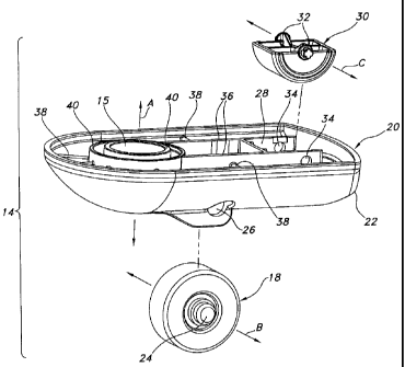
On an underside 12 of the vacuum cleaner, a stair hugging swivel
wheel assembly 14 mounts thereto. In one embodiment, it mounts by way of
an opening 15 that connects to a post 16 of the cannister assembly and
becomes secured via snap-fitting or other mechanical fasteners. In general,
the
stair hugging swivel wheel assembly has a wheel 18, especially a caster wheel,
rotatably mounted to a housing 20 thereof such that, in combination with the
rear wheels 6 of the canister assembly 8, it provides multi-directional
wheeled
motion to the canister assembly upon a user's actions of pulling or pushing.
Specifically, as an operator pulls the canister assembly 8 across a floor, the
stair hugging swivel wheel assembly 14 pivots and the wheel 18 functions to
guide the canister assembly 8 to follow the operator. In one embodiment, the
housing 20 of the stair hugging swivel wheel assembly pivots about an axis A
in a circular motion (clockwise CW or counterclockwise CCW depending
upon forces applied by the user) about a substantially circular track 21
centered by the post 16.
CA 02588032 2007-05-16
6
With reference to Figure 2, the wheel 18 mounts to the housing 20 on
a stair engaging face 22 side of the stair hugging swivel wheel assembly such
that it rotates about an axis B existing substantially perpendicular to the
axis
A. In various embodiments, the wheel 18 mounts via mechanical arms (not
shown) that attach to axial projections 24 on either side of the wheel or
mounts by inserting projections 24 into holes 26 defined by the housing.
Alternatively, an axle through the wheel (not shown) may serve as a rotation
axis.
An interior 28 of the housing mounts a pendulum 30 that freely rotates
about an axis C (substantially parallel to axis B) according to the effects of
gravity. In one embodiment, the pendulum 30 embodies a truncated cylinder
shaped apparatus having projections 32 on either side thereof that mate by
insertion into holes 34 defmed by walls 36 of the housing. Pluralities of fins
3 8 project in various ways within the interior to provide structural support
for
the walls and other components of the stair hugging swivel wheel assembly
including concentric walls 40 that define the opening 15 about which the
housing pivots.
By comparing Figures 3A and 3B, skilled artisans can observe the
different positions attainable by the pendulum 30 as the stair hugging swivel
wheel assembly, and ultimately the attached canister assembly, changes
orientation from a normal, horizontal canister operative position (Figure 3A)
to an upright or vertical canister operative position (Figure 3B), such as
during
a stair cleaning operation. Specifically, the pendulum of Figure 3A embodies
a pendulum at rest having its terminal end portions 42, 44 at the same
relative
vertical distance from tops 35 of the housing walls 36. In contrast, the
pendulum 30 of Figure 3B embodies a pendulum at rest pivoted about its
projections 32 such that its terminal end portion 42 projects above tops 35 of
CA 02588032 2007-05-16
7
walls 36 and projects from the housing 20 in a direction opposite the stair
engaging face 22. Meanwhile, the other terminal end portion 44 sinks relative
to the tops 35 of the walls 36. In this manner, the terminal end portion may
engage or otherwise mate with a recess 50 (referring also to Figure 1) co-
located with the circular track 21 within a boundary 52 thereof. As a result,
the stair hugging swivel wheel assembly becomes locked relative to the
canister assembly and cannot pivot about its axis A thereby stabilizing the
canister assembly.
Appreciating that the stair hugging swivel wheel assembly might not
have an orientation in the circular track lending relative alignment between
the
terminal end portion 42 and the recess 50 to cause instant mating when the
canister vacuum cleaner first becomes oriented upright, skilled artisans
should
appreciate the weight of the whee118 creates a moment arm about axis A such
that the stair hugging swivel wheel assembly 14 will, under the influence of
gravity, pivot about axis A when inclined so that an end 23 of the housing 20
will move clockwise or counterclockwise in a direction toward the recess 50.
Thus, eventually, the terminal end portion 42 of the pendulum will slip into
the depth of the recess and cause a locked or latched position of the stair
hugging swivel wheel assembly. Ultimately, this inhibits or prevents the stair
hugging swivel wheel assembly from further pivoting motion thereby allowing
effective stabilization of the canister assembly against a stairway or the
like.
Of course, the stair engaging face 22 may comprise a non-skid, high friction
material (indicated as the word Stairgrip or Stairgripper) or include an
insert
or pad of such material if desired. Additionally, the lower rear end 57 or
edge
58 of the canister assembly 8 may also include a stair engaging face with or
without an insert or pad of non-skid, high friction material.
CA 02588032 2007-05-16
8
It should be appreciated that while the canister assembly of Figure 3B
corresponds to an upright or vertical position, the pendulum 30 will exhibit
comparable behavior under the influence of gravity whenever the canister
assembly becomes oriented in any inclined position beyond the completely
upright one shown. Thus, with reference to Figure 4, an angle a shows a
canister vacuum cleaner 10 inclined with respect to a dashed-outline of a
stairway. In a preferred range, the angle ranges from about 2 to about 90 or
more. More preferably, the angle ranges from about 25 to about 65 .
In summary, numerous benefits result from employing the concepts of
the present invention. During normal floor cleaning operation, the stair
hugging swivel wheel assembly functions to guide the canister assembly
across the floor and follow the operator as the operator uses the hose to pull
the vacuum cleaner. In contrast, when the vacuum cleaner becomes tilted or
inclined and positioned on a stairway, the stair hugging swivel wheel assembly
14 becomes locked by engagement of the pendulum 30 in the recess 50 of the
circular track 21. In this manner, the stair engaging face 22 of the housing
20
becomes properly oriented to stabilize the vacuum cleaner.
The foregoing description of the preferred embodiment of the invention
has been presented for purposes of illustration and description. It is not
intended to be exhaustive or to limit the invention to the precise form
disclosed. Obvious modifications or variations are possible in light of the
above teachings.
For example, while the canister vacuum cleaner 10 illustrated herein
depicts a stair engaging face 22 on the housing of the stair hugging swivel
wheel assembly 14, those skilled in the art should appreciate that it could
alternatively embody a component separate and distinct from the stair hugging
CA 02588032 2007-05-16
9
swivel wheel assembly. Other alternate embodiments include mounting the
pendulum and/or caster wheel directly to the canister assembly absent the
stair
hugging swivel wheel assembly. In addition, the invention contemplates
interchangeability while accomplishing the described functions. For example,
one or the other of the caster wheel and pendulum may mount on the canister
assembly while the other mounts on the stair hugging swivel wheel assembly.
Alternatively, the pendulum may mount on the canister assembly while the
recess for mating therewith mounts on the stair hugging swivel wheel
assembly.
Finally, the embodiments herein were chosen and described to provide
the best illustration of the principles of the invention and its practical
application to thereby enable one of ordinary skill in the art to utilize the
invention and understand variations for accomplishing the same. Accordingly,
the claims include all modifications and variations within their scope when
interpreted in accordance with the breadth to which they are fairly, legally
and
equitably entitled. The drawings and preferred embodiments, however, do not
and are not intended to limit the ordinary meaning of the claims and their
fair
and broad interpretation in any way.