Note: Descriptions are shown in the official language in which they were submitted.
CA 02588228 2007-05-22
WO 2006/062584 PCT/US2005/037500
DESCRIPTION
VERTICAL DOOR LOCKING SYSTEM
WITH SOLENOID RELEASED LATCH
Technical Field
The present invention relates to locks for doors that open vertically, such as
garage doors, rollup doors and overhead doors. More specifically, the present
invention relates to electrically controlled locks for vertical doors
Description of Related Art
Doors that open vertically are widely used in self-storage centers, as garage
doors and as loading and access doors. Vertical doors include various types of
vertically sliding and rollup doors that are typically provided with
horizontal
corrugations allowing the door to bend to a horizontal position or form a
horizontal
roll above the door opening.
A typical method of locking vertical doors in self-storage installations uses
a
latch attached to the vertical door. The latch includes a sliding latchbolt
that
extends horizontally outward from the side of the vertical door and through
the
adjacent vertical door guide or doorframe. When extended, the latchbolt
prevents
the door from being lifted. To prevent the latch from being withdrawn, a key
operated padlock is typically attached between the body of the latch and the
latchbolt, holding the latchbolt in the latched position.
To remove the padlock, the self-storage customer is provided with a key.
When the key is lost, or the storage area is rented to another customer, the
key must
be replaced and/or the lock must be changed. This represents an ongoing
problem
due to both cost and the labor time required. Locks and keys must also be
changed
when a customer has failed to pay applicable storage fees.
These difficulties have created a demand for electrically controlled vertical
door locks. Such locks may be operated by a keypad, a magnetic stripe card, an
RFID tag that sends a coded signal when proximate an RFID reader or by other
electrically based security systems. Although sophisticated electrically
controlled
locks may be modified for vertical door use, there exists a need for a low
cost
electrically controlled lock for vertical doors.
One design difficulty in electrifying the simple mechanically operated sliding
latchbolt design described above is that the latch mechanism and lock are
attached
to the vertical door. The vertical motion of the door makes it difficult and
CA 02588228 2007-05-22
WO 2006/062584 PCT/US2005/037500
-2-
expensive to supply electrical power to a latch mechanism that must move
whenever the door is opened or closed.
Bearing in mind the problems and deficiencies of the prior art, it is
therefore
an object of the present invention is to provide a low cost, simple and
reliable
vertical door locking system that electronically controls access to a secure
area.
Another object of the present invention is to provide a vertical door locking
system that can be installed on existing vertical doors having conventional
mechanically operated sliding latches of the type described above.
Yet another object of the present invention is to provide a vertical door
locking system that is electrically operated but requires no electrical
connection to
the portion of the lock on the moving vertical door.
Still other objects and advantages of the invention will in part be obvious
and will in part be apparent from the specification.
Disclosure of Invention
The above and other objects, which will be apparent to those skilled in art,
are achieved in the present invention which is directed to a vertical door
locking
system including an electrically operable solenoid and a latch. The solenoid
includes a solenoid rod movable between an extended position and a retracted
position. The latch includes a latchbolt with an opening at an end thereof of
sufficient size to receive the solenoid rod and the latchbolt is movable
between a
latched position and an unlatched position.
The latch is mounted on the vertical door to be locked. The solenoid is
mounted on a solenoid mount at a fixed location near the edge of the door.
When
the latchbolt is in the latched position it prevents the door from opening.
The
solenoid mount holds the solenoid with the solenoid rod extending
perpendicular
to the latchbolt. The solenoid rod prevents the latchbolt from moving to the
unlatched position when the solenoid rod is in the extended position and
received
in the opening in the end of the latchbolt.
The latchbolt is preferably of the manually slidable type and includes a latch
body for mounting the latchbolt on the door. The latchbolt is slidably held by
the
latch body which is preferably specially shaped to mount the latchbolt on a
corrugated surface of a vertical door.
The solenoid rod is spring operated and the end of the latchbolt and the
solenoid rod are shaped to cooperatively interact and drive the solenoid rod
towards the retracted position as the latchbolt is moved from the unlatched to
the
CA 02588228 2007-05-22
WO 2006/062584 PCT/US2005/037500
-3-
latched position. The spring operated solenoid rod thereafter returns to the
extended position and engages the opening in the end of the latchbolt as the
latchbolt reaches the latched position.
The cooperative interaction may be provided by a bevel on the end of the
Iatchbolt, a rounded end on the solenoid rod, or by providing both features or
other
angled elements to drive the solenoid rod towards the retracted position as
the
latchbolt is moved from the unlatched to the latched position.
The solenoid rod is preferably manually movable to the retracted position to
permit the door to be unlocked from inside without electrical power. In the
preferred design, the solenoid rod includes a knob at an end thereof whereby
the
solenoid rod may be manually moved to the retracted position against spring
biasing pressure provided by the solenoid.
The solenoid mount is preferably adapted for mounting to a guide rail for the
vertically opening door. The solenoid mount also preferably includes a
latchbolt
opening for receiving the latchbolt, the latchbolt opening being shaped to
steer the
Iatchbolt into a desired alignment relative to the solenoid and the solenoid
rod as
the latchbolt moves to the latched position.
In another aspect of the invention, the solenoid rod is weakened to permit
the solenoid rod to break when an excess force is applied to the latchbolt
whereby
the latchbolt may be moved to the unlatched position by breaking the solenoid
rod
in the event the solenoid fails to operate electrically.
The invention also includes a vertical door and vertical door locking system
including a vertically opening door, a guide rail having a latchbolt opening,
the
guide rail acting to vertically guide the door between opened and closed
positions,
an electrically operable solenoid having a solenoid rod moveable between an
extended position and a retracted position, a latch and a solenoid mount. The
latch
is adapted for attachment to the door and includes a Iatchbolt movable between
a
latched position to prevent the door from opehing and an unlatched position to
allow the door to open. The latchbolt has an opening at an end thereof of
sufficient
size to receive the solenoid rod and the latchbolt extends through the
latchbolt
opening when the door is in the closed position and the Iatchbolt is in the
latched
position. The solenoid mount is attached to the guide rail near the latchbolt
opening and holds the solenoid with the solenoid rod extending perpendicular
to
the latchbolt. The solenoid rod prevents the latchbolt from moving to the
CA 02588228 2007-05-22
WO 2006/062584 PCT/US2005/037500
-4-
unlatched position when the solenoid rod is in the extended position and
received
in the opening in the end of the latchbolt.
Brief Description of the Drawings
The features of the invention believed to be novel and the elements
characteristic of the invention are set forth with particularity in the
appended
claims. The figures are for illustration purposes only and are not drawn to
scale.
The invention itself, however, both as to organization and method of
operation,
may best be understood by reference to the detailed description which follows
taken in conjunction with the accompanying drawings in which:
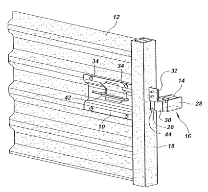
Fig. 1 is a perspective view of a vertical door locking system according to
the
present invention. The locking system is shown from the front side of the door
as
installed on a corrugated vertical door, and only a portion of the vertical
door and a
portion of a guide rail for the vertical door are illustrated.
Fig. 2 is an exploded perspective view of the vertical door locking system in
Fig. 1.
Fig. 3 is a detail perspective view of the vertical door locking system in
Fig.1. This view shows the solenoid, solenoid mount and a portion of the
extended
latchbolt as they appear from the backside of the door.
Fig. 4 is a detail perspective view of a second embodiment of the invention
showing a modified solenoid and solenoid mount.
Mode(s) for Carrying Out Invention
In describing the preferred embodiment of the present invention, reference
will be made herein to Figs. 1-4 of the drawings in which like numerals refer
to like
features of the invention.
Referring to Figs. 1-3, the present invention includes a latch 10 and a
solenoid 14. When latched, the latch functions to prevent vertical door 12
from
opening and the solenoid functions to prevent the latch from being unlatched
until
the solenoid is electrically operated. The latch is directly mounted on, and
moves
with, the vertical door 12 as it is opened and closed. The solenoid 14 is held
in a
fixed position by solenoid mount 16, which may be attached to vertical door
guide
18 or to the wall, doorframe or other support adjacent to the edge of the
vertical
door.
CA 02588228 2007-05-22
WO 2006/062584 PCT/US2005/037500
-5-
As may be seen in the exploded view in Fig. 2, the latch 10 includes a
Iatchbolt 20 which slides horizontally on a latch body 11. The latchbolt moves
in
the directions indicated by arrow 22 between an extended latched position
(latchbolt to the right - as illustrated) and a retracted unlatched position
(Iatchbolt to
the left). The latchbolt 20 includes an opening 24 at the right end thereof
sized to
receive a solenoid rod 26 that extends perpendicularly outward from the
solenoid
14.
In the design seen in Figs. 1-3, the solenoid mount 16 comprises a pair of U-
shaped brackets 28, 30 and an L-shaped bracket 32 which allow the solenoid to
be
mounted to an adjacent wall or doorframe. In the design seen in Fig. 4,
however,
the solenoid mount comprises a single U-shaped mount 16' attached directly to
the
guide rail 18.
As may be seen in Fig. 2, the body of the latch 10 is specially shaped to fit
the horizontal corrugations found on the vertical door 12. The horizontal
corrugations of the door allow the door to flex so that it may be rolled above
the
door opening or turned to a horizontal orientation above the enclosed space
behind
the door. The latch 10 is attached to the door 12 with four bolts 34.
The bolts 34, which are preferably carriage bolts, extend through
corresponding holes 36 in the door 12 and are secured on the backside with
nuts
38. See also Fig. 3. The bolt pattern provided by holes 36 preferably
corresponds
to existing installations of mechanically operated vertical door latches so
that the
electrically operated latch of the present invention may be retrofitted to
installed
vertical doors.
In the most highly preferred design or the invention, the Iatchbolt including
opening 24 is a retrofit replacement for an existing latch design having a
latchbolt
without opening 24 so that the only the latchbolt needs to be replaced and the
solenoid and mount installed. The solenoid mount 16 seen in Figs. 1-3 is
attached
with screws 40 to an adjacent wall. In the second embodiment seen in Fig. 4,
solenoid mount 16' is directly attached to the guide rail 18.
The latch 10 includes a handle 42 connected to the Iatchbolt20, which
allows the user to slide the Iatchbolt between the unlatched position and the
latched position. When the door 12 is closed, the latchbolt 20 is aligned with
opening 44 in the guide rail 18. When the latchbolt 20 is then moved to the
latched position, the end of the latchbolt 20 with the opening 24 extends
through
latchbolt opening 44 and thereby prevents the vertical door 12 from being
raised
CA 02588228 2007-05-22
WO 2006/062584 PCT/US2005/037500
-6-
and opened. When the latch handle 42 is moved to the left, the latchbolt 20 is
moved to the unlatched position and the door 12 may be raised to permit access
to
the secured space.
The solenoid mount 16 holds the solenoid 14 with the solenoid rod 26
perpendicular to the latchbolt. When the vertical door is closed and the
latchbolt is
moved to the right, the latchbolt 20 extends through latchbolt opening 44 and
opening 24 in the latchbolt 20 aligns with the solenoid rod 26. The solenoid
is
electrically operated and moves the solenoid rod 26 between extended (locked)
and retracted (unlocked) positions.
When the solenoid rod 26 is extended it engages opening 24 in the latchbolt
and prevents the latchbolt from being moved to the unlatched position. Upon
receipt of an electrical control signal, the solenoid rod retracts and the
latch 20 is
again free to move to the unlatched position so that the door 12 may be
opened.
In the preferred design, the solenoid includes a spring that biases the
solenoid rod towards the extended position. The -tip of the solenoid rod is
preferably rounded (see Fig. 4) and the end of the latchbolt 20 is provided
with a
bevel 46 (see Fig. 3). The bevel 46 on the latchbolt 20 and the rounded
hemispherical shape of the end of the solenoid rod 26 cooperate to allow the
Iatchbolt to be moved from the unlatched position to the latched position even
when the solenoid rod is in the extended position.
With the door closed, but unlatched, and the solenoid unpowered, with the
solenoid rod spring biased towards the extended position, the sliding
latchbolt may
be moved towards the latched position. As the latchbolt approaches the
solenoid
rod, the bevel 46 on the end of the latchbolt contacts the rounded end of the
solenoid rod 26 and drives the spring biased solenoid rod towards the
retracted
position. This allows the latchbolt 20 to extend fully to the latched position
without
interference from the solenoid rod.
As opening 24 reaches alignment with the solenoid rod, the spring action of
the solenoid returns the solenoid rod to the extended position and thereby
locks the
latch until the solenoid is energized again. This operation allows the
vertical door
to be closed and latched without requiring the solenoid to be electrically
retracted
during the Iocking operation.
Fig. 4 illustrates a second embodiment of the invention. Opening 24 in the
latchbolt has been enlarged to form an elongated slot 24'. This elongation
allows
the solenoid rod to engage the latchbolt in different installations without
concern
CA 02588228 2007-05-22
WO 2006/062584 PCT/US2005/037500
-7-
for accurate left/right horizontal alignment between the slot 24' and the
solenoid
rod 26', which has also been modified.
In the design seen in Fig. 4, the solenoid mount 16' is formed from a single
piece which reduces cost and parts count as compared to the solenoid mount 16
in
Figs. 1-3. The one piece solenoid mount 16' is directly mounted to the guide
rail
18 which simplifies installation and reduces alignment problems. Another
advantage of the solenoid mount 16' in Fig. 4 is the incorporation of an
integral
latchbolt opening 50 in the solenoid mount.
The latchbolt opening 50 is aligned with opening 44 in the guide rail 18 and
includes at least one angled element 52 which acts to steer the latchbolt into
a
desired alignment relative to the solenoid and the solenoid rod as the
Iatchbolt
moves to the latched position. Angled element 52 is an integral piece of the
latchbolt opening 50 and the solenoid mount 16' and is preferably formed by
punching to provide an inwardly and downwardly angled guide surface.
As the latchbolt enters the latchbolt opening 50, angled element 52 located
above the latchbolt contacts the top of the latchbolt and vertically guides
the
latchbolt down to ensure vertical alignment between opening 24' and the
latchbolt
rod 26'. In the preferred design, there is a second angled element 56 below
the
latchbolt to inwardly and upwardly guide the latchbolt. The two angled
elements
52, 56 define up/down vertical alignment for the latchbolt.
In addition to the angled elements above and below the latchbolt, the
preferred design includes corresponding inwardly angled elements 58, 60 on the
left and right sides of the latchbolt. Inwardly angled elements 58, 60 define
a
front/back horizontal alignment for the latchbolt and ensure that the
latchbolt will
properly push the solenoid rod back as it is inserted and that the solenoid
rod will
fully engage and properly disengage from opening 24' in the latchbolt.
Another feature of the invention seem in Fig. 4 is knob 54 attached to an end
of the Iatchbolt rod 26, which extends out the back of the solenoid 14'. Knob
54
allows the solenoid rod 16' to be manually retracted so that the vertical door
may
be manually unlocked from the back side of the door. This prevents anyone from
being trapped within the secured area behind door 12. The knob 54 is simply
pulled against the spring bias pressure of the solenoid to retract the
solenoid rod
and the Iatchbolt is manually moved to the unlatched position.
The solenoid may be operated by any type of electrical security system
desired. Available systems include magnetic stripe card readers, biometric
sensors,
CA 02588228 2007-05-22
WO 2006/062584 PCT/US2005/037500
-8-
smart cards, proximity sensors, such as radio frequency ID tags and chips,
wireless
and wired network controls, keypad entry systems and the like.
While the present invention has been particularly described, in conjunction
with a specific preferred embodiment, it is evident that many alternatives,
modifications and variations will be apparent to those skilled in the art in
light of
the foregoing description. It is therefore contemplated that the appended
claims
will embrace any such alternatives, modifications and variations as falling
within
the true scope and spirit of the present invention.
Thus, having described the invention, what is claimed is: