Note: Descriptions are shown in the official language in which they were submitted.
CA 02588286 2012-08-03
HAND-ACTUATED DEVICE FOR REMOTE MANIPULATION OF A
GRASPING TOOL
FIELD OF THE INVENTION
[0001] This invention relates to articulating mechanisms and applications
thereof,
including the remote guidance and manipulation of surgical or diagnostic
instruments and
tools. In particular, this invention relates to hand-actuated mechanisms for
the remote
manipulation of body tissue.
BACKGROUND OF THE INVENTION
[0002] The ability to easily remotely manipulate instruments and tools is
of interest in a
wide variety of industries and applications, in particular where it is desired
to control
movements of instruments or tools in spaces difficult to access by hand, or
areas that might
otherwise present a risk or danger. These can include situations where the
targeted site for
the application of a tool or instrument is difficult to access during surgical
procedures, or the
manufacture or repair of machinery, or even during commercial and household
uses, where
manual access to a targeted site is restricted or otherwise. Other situations
can include, e.g.,
industrial applications where the work environment is dangerous to the user,
for example,
workspaces exposed to dangerous chemicals. Still other situations can include,
e.g., law
enforcement or military applications where the user may be at risk, such as
deployment of a
tool or instrument into a dangerous or hostile location.
100031 Using surgical procedures as an illustrative example, procedures
such as
endoscopy and laparoscopy typically employ instruments that are steered within
or towards a
target organ or tissue from a position outside the body. Examples of
endoscopic procedures
include sigmoidoscopy, colonoscopy, esophagogastroduodenoscopy, and
bronchoscopy.
Traditionally, the insertion tube of an endoscope is advanced by pushing it
forward, and
retracted by pulling it back. The tip of the tube may be directed by twisting
and general
up/down and left/right movements. Oftentimes, this limited range of motion
makes it
difficult to negotiate acute angles (e.g., in the rectosigmoid colon),
creating patient
discomfort and increasing the risk of trauma to surrounding tissues.
[0004] Laparoscopy involves the placement of trocar ports according to
anatomical
landmarks. The number of ports usually varies with the intended procedure and
number of
instruments required to obtain satisfactory tissue mobilization and exposure
of the operative
field. Although there are many benefits of laparoscopic surgery, e.g., less
postoperative pain,
1
CA 02588286 2012-08-03
early mobilization, and decreased adhesion formation, it is often difficult to
achieve optimal
retraction of organs and maneuverability of conventional instruments through
laparoscopic
ports. In some cases, these deficiencies may lead to increased operative time
or imprecise
placement of components such as staples and sutures.
[0005] Steerable catheters are also well known for both diagnostic and
therapeutic
applications. Similar to endoscopes, such catheters include tips that can be
directed in
generally limited ranges of motion to navigate a patient's vasculature.
[0006] There have been many attempts to design endoscopes and catheters
with
improved steerability. For example, U.S. 3,557,780 to Sato; U.S. 5,271,381 to
Ailinger et al.;
U.S. 5,916,146 to Alotta et al.; and U.S. 6,270,453 to Sakai describe
endoscopic
instruments with one or more flexible portions that may be bent by actuation
of a single set
of wires. The wires are actuated from the proximal end of the instrument by
rotating pinions
(Sato), manipulating knobs (Ailinger et al.), a steerable arm (Alotta et al.),
or by a pulley
mechanism (Sato).
[0007] U.S. 5,916,147 to Boury et al. discloses a steerable catheter having
four wires
that run within the catheter wall. Each wire terminates at a different part of
the catheter. The
proximal end of the wires extend loosely from the catheter so that the
physician may pull
them. The physician is able to shape and thereby steer the catheter by
selectively placing the
wires under tension.
[0008] Although each of the devices described above are remotely steerable,
their range
of motion is generally limited, at least in part because typically only a
single cable set is
employed in connecting links or segments of the steerable elements. As such,
independent
movement at each link or segment is not possible. Rather, the distal links or
segments bend
together as a unit or units. The steering mechanisms may also be laborious to
use, such as in
the catheter of Boury et al. where each wire must be separately pulled to
shape the catheter.
Further, in the case of, e.g., endoscopes and steerable catheters that use
knob and pulley
mechanisms, it requires a significant amount of training to become proficient
in
maneuvering the device through a patient's anatomy.
[0009] Consequently, a device with enhanced remote maneuverability to
controllably
navigate complex anatomy may allow more efficient and precise advancement and
deployment of surgical and diagnostic instruments and tools, as well as help
decrease trauma
to surrounding tissues, minimize patient discomfort, and decrease operative
time and perhaps
even patient morbidity during various surgical procedures. It would also be
advantageous for
2
CA 02588286 2012-08-03
such a device to provide a more intuitive and facile user interface to achieve
such enhanced
maneuverability.
[0010] A user interface that accurately translates finger movement of the
human hand to
a surgical instrument or tool is one way of achieving remote enhanced
maneuverability.
Although many attempts have been made to implement such a device, such as
described in
U.S. 5,441,494 to Ortiz; U.S. 5,807,376 to Viola et al.; and U.S. 5,813,813 to
Daum et al.,
there still exists a need for a device with improved control and range of
motion.
[0011] Thus, a device that not only provides a hand user interface, but an
actuation
mechanism that allows for close simulation of human hand movements to enhance
remote
maneuverability is highly desirable.
SUMMARY OF THE INVENTION
100121 The present invention provides an articulating mechanism useful for
a variety of
purposes including but not limited to the remote manipulation of instruments
such as
surgical or diagnostic instruments or tools, including but not limited to
endoscopes,
catheters, Doppler flow meters, microphones, probes, retractors, dissectors,
staplers, clamps,
graspers, scissors or cutters, ablation or cauterizing elements, and the like.
The articulating
mechanism may be used to steer these instruments within a body region or to a
target site
within a body region of a patient, and can further be employed to actuate or
facilitate
actuation of such instruments and tools.
[0013] In one variation, the articulating mechanism includes multiple pairs
of links, each
link of each pair being maintained in a spaced apart relationship relative to
the other link of
the pair, and multiple sets of cables, with each cable set connecting the
links of a discrete
pair to one another and terminating at the links of each discrete pair, such
that movement of
one link of a pair causes corresponding relative movement of the other link of
the pair. The
relative movement at the distal end of the articulating mechanism corresponds
to that at the
proximal end.
[0014] In another variation, the articulating mechanism includes a
continuous flexible
member. The continuous flexible member includes multiple pairs of segments,
with each
segment of each pair being maintained in a spaced apart relationship relative
to the other
segment of the pair, and multiple sets of cables, with each set connecting the
segments of a
discrete pair to one another and terminating at the segments of each discrete
pair, such that
movement of one segment of a pair causes corresponding relative movement of
the other
3
CA 02588286 2012-08-03
segment of the pair. In some instances, the continuous flexible member may be,
e.g., a
catheter with a plurality of lumens, where each cable set terminates at a
different axial
location along the length of the catheter. In other instances the continuous
flexible member
may have a helical arrangement, with each segment corresponding to one turn of
the helix. If
desired, a flexible linkage may be placed between the helical segments or
links.
[0015] Variations of the articulating mechanism can also include segments
or links that
may include a channel for receiving a locking rod that can secure and retain
the proximal end
of the articulating mechanism in a fixed position. Instead of a rod, a locking
sleeve may be
fitted over the proximal end of the mechanism to secure and retain the
proximal end in a
fixed position.
[0016] A surgical or diagnostic tool may be attached to, and extend from,
the distal end
of articulating mechanisms according to the invention, or the articulating
mechanisms may
be otherwise incorporated into such tools. Examples of surgical or diagnostic
tools include,
but are not limited to, endoscopes, catheters, Doppler flow meters,
microphones, probes,
retractors, dissectors, staplers, clamps, graspers, scissors or cutters, and
ablation or
cauterizing elements.
[0017] A plurality of articulating mechanisms may also be combined in such
a way that
a user's finger movements can be remotely mimicked to manipulate an object or
body tissue.
In one variation, the mechanisms form a hand-actuated apparatus that includes
multiple pairs
of links, with each link of each discrete pair being maintained in a spaced
apart relationship
relative to the other link of the pair, the links incorporated into proximal
and distal ends of
the apparatus with the links of corresponding pairs located on the proximal
and distal ends
respectively, multiple sets of cables, with each set connecting the links of a
discrete pair to
one another, and a user hand interface at a proximal end of the apparatus
configured to
removably secure one or more digits of a human hand for movement, such that
movement of
said digit when secured to the interface moves one or more links of a pair at
said proximal
end and causes corresponding relative movement of the other one or more links
of the pair at
a distal end of the apparatus. In some instances, at least one link of a pair
is an elongate link.
[0018] In another variation, the hand-actuated apparatus includes a
proximal end having
a user hand interface configured to removably secure one or more digits of a
human hand for
movement, such that flexion of the digit when secured is translated into a
bending movement
at the distal end effector portion. In a further variation, the user hand
interface includes a
4
CA 02588286 2012-08-03
finger slide where translational movement of the finger slide is translated
into a bending
movement at the effector portion.
[0019] The hand-actuated devices of this invention also include one or more
joints at
their proximal and distal ends that have the range of motion of a distal
interphalangeal (DIP)
joint, proximal interphalangeal (PIP) joint, or metacarpal phalangeal (MCP)
joint. In some
instances, control of movement of a proximal joint, such as a MCP joint, is
independent of
control of one or more distal joints, e.g., a PIP joint or DIP joint. In other
instances,
movement at the proximal end of the device, e.g., movement of one link of a
pair or
translational movement of a finger slide, is proportionally scaled to the
movement at the
distal end of the mechanism, e.g., at the other link of the pair or at the
effector portion.
BRIEF DESCRIPTION OF THE DRAWINGS
[0020] Figures 1A-1E show perspective views of an articulating mechanism
according to
one variation of the invention, with multiple pairs of links connected by
corresponding sets
of cables. Figure IA shows the mechanism in its natural configuration. Figures
1B to lE
show the mechanism in various states of manipulation.
[0021] Figure 1F is a perspective view of the distal end of an articulating
mechanism
similar to that of Figure lA with the end manipulated into multiple
curvatures.
[0022] Figures 2A-2E depict end, side, and perspective views of a link for
use in an
articulating mechanism according to another variation of the invention.
[0023] Figures 3A-3C are cross-sectional views of links similar to those of
Figures
2A-2E having variously shaped stem portions and corresponding recesses. In
Figures 3A and
3B, the distal end of the stem portions are convex, while in Figure 3C it is
ball-shaped. The
recesses are cone-shaped in Figure 3A, concave in Figure 3B, and ball-shaped
in Figure 3C.
[0024] Figure 3D is a cross-sectional view of links for use in an
articulating mechanism
according to another variation of the invention with spherical elements
disposed between the
links. Figure 3E is a cross-sectional view of links and spherical elements
similar to those of
3D and which also include a center channel extending through and
communicating between the links and spherical elements.
[0025] Figures 4A-4C are cross-sectional views of links for use in an
articulating
mechanism according to a variation of the invention showing various modes of
connecting
cables to the links.
CA 02588286 2012-08-03
[0026] Figures 5A and 5B show an individual link for use in an articulating
mechanism
according to another variation of the invention. Figure 5A is a perspective
view. Figure 5B is
an end view. The depicted link includes lumens and channels for receiving and
passing
through of cables and other elements.
[0027] Figures 6A-6C show perspective views of articulating mechanisms
associated
with a surgical clamp according to variations of the invention.
[0028] Figure 7 is a perspective view of an articulating mechanism
associated with a
catheter according to a variation of the invention.
[0029] Figure 8 is a perspective view of an articulating mechanism
associated with an
endoscope according to another variation of the invention.
[0030] Figures 9A and 9B are perspective views of an articulating mechanism
used to
remotely form a retractor. In Figure 9A, the retractor is "u" shaped. In
Figure 9B, the
retractor has a triangular retracting surface.
[0031] Figure 9C is a perspective view of an articulating mechanism
according to
another variation of the invention where the mechanism is attached to the hand
of a user.
100321 Figures 10A-10B show perspective views of an articulating mechanism
according
to another variation of the invention having a continuous flexible member that
includes
helical segments with multiple pairs of such segments connected by
corresponding sets of
cables. Figure 10B is an enlarged view, with parts broken away, of the helical
segments
shown in Figure 10A.
[0033] Figure 11 is a perspective view of an articulating mechanism
according to yet
another variation of the invention having a continuous flexible member with a
plurality of
through lumens with multiple pairs of segments connected by corresponding sets
of cables.
[0034] Figures 12A-12B are perspective views of distal ends of an
articulating
mechanism according to a further variation of the invention having attached
tissue ablation
elements.
[0035] Figures 13A-13F show the distal end of an articulating mechanism
according to
Figure 12 being remotely maneuvered to create ablative cardiac lesions.
[0036] Figure 14 is a perspective view of a hand-actuated apparatus having
finger loops
according to one variation of the invention. The apparatus is shown in an
unactuated state.
[0037] Figure 15 shows placement of a human hand in the hand-actuated
apparatus of
Fig. 14.
[0038] Figure 16 is an expanded perspective view of the finger loops of
Figure 14.
6
CA 02588286 2012-08-03
[0039] Figure 17 is a perspective view of the hand-actuated apparatus of
Figure 15 in an
actuated state.
[0040] Figure 18 is a perspective view of a hand-actuated apparatus having
finger slides
according to one variation of the invention. The apparatus is shown in an
unactuated state.
[0041] Figure 19 shows placement of a human hand in the hand-actuated
apparatus of
Figure 18.
[0042] Figure 20 is a perspective view of the hand-actuated apparatus of
Figure 19 in an
actuated state.
[0043] Figure 21 is a perspective view of a handle of the hand-actuated
device according
to one variation of the invention.
[0044] Figure 22 is a side view of the slide mechanism according to one
variation of the
invention.
[0045] Figure 23 is a side view of the slide mechanism according to Figure
18.
[0046] Figure 24 is a perspective view of the slide mechanism of Figure 23,
partially
disassembled.
100471 Figure 25 is a cross-sectional view of the slide mechanism of Figure
23, taken
along line B-B, showing an end joint roller having twice the diameter of a
middle joint
roller.
[0048] Figure 26 is a perspective view of the slide mechanism of Figure 23
showing the
cable connections to the rollers and a base joint according to one variation
of the invention.
[0049] Figure 27 is a perspective view of a handle showing routing of
cables.
[0050] Figure 28 is an expanded perspective view of a molded handle of a
user hand
interface according to one variation of the invention, with cables traveling
through channels
in the interface.
[0051] Figure 29 is an expanded cross-sectional view of a hollow handle of
a user hand
interface according to another variation of the invention showing the cables
being routed by
a pulley.
[0052] Figure 30 is an expanded cutaway view of the effector portion of the
hand-
actuated apparatus of Figure 14.
[0053] Figures 31A-31C are expanded cutaway views of the effector joints in
Figure 30.
[0054] Figure 32 is an expanded side view of the effector joints in Figures
31A and 31B
with the joints vertically oriented.
7
CA 02588286 2012-08-03
[0055] Figure 33 is an expanded side view of the effector joint in Figure
31C with the
joints vertically oriented.
[0056] Figure 34 is an exploded view of an effector link that forms a part
of the effector
portion of Figure 30.
DETAILED DESCRIPTION OF THE INVENTION
[0057] Articulating mechanisms according to the invention generally include
multiple
pairs of links or segments and multiple sets of cables. The articulating
mechanisms may be
made from individual, spaced apart segments, i.e., links, or from segments
formed from a
continuous flexible member. The terms "link" and "segment" as used herein
refer to a
discrete portion or defined area at one end of the mechanism that corresponds
to another
discrete portion or defined area at the opposite end of the mechanism. In any
event, the
articulating mechanism will include a plurality of links or segments that are
members of
discrete pairs. The links or segments form a proximal end and a distal end,
with one link or
segment of each pair being situated at the proximal end, and the other link or
segment at the
distal end. As further described below, links or segments formed from a
continuous flexible
member may be in the form of, e.g., a continuous tube, or may be situated in,
e.g., a helical
arrangement, where each segment corresponds to one turn of the helix.
[0058] Each cable set connects the links or segments of a discrete pair to
one another so
that movement of one link or segment of a pair causes a corresponding movement
of the
other link or segment in the pair. The ability to manipulate individual links
allows for the
mechanism to readily form complex three-dimensional configurations and
geometries as is
further detailed herein. With conventional articulating devices that rely on
cable sets or
wires, it is difficult to obtain such complex geometries because such devices
are typically
designed such that the steering cables or wires pass through each segment and
terminate in a
distal-most segment. Thus, all the segments bend together in a coordinated
response to
movement of the wire or cable set, typically in a curved, or arcuate fashion.
For example, the
device described by Alotta et al. in U.S. 5,916,146 has such a configuration.
[0059] For purposes of illustration, articulating mechanisms of the
invention will be
described in the context of use for the remote guidance, manipulation and/or
actuation of
surgical or diagnostic tools and instruments in remote accessed regions of the
body, or for
the remote manipulation of body tissues. The terms "instrument" and "tool" are
herein used
interchangeably and refer to devices that are usually handled by a user to
accomplish a
8
CA 02588286 2012-08-03
specific purpose. The term "region" as used herein refers to any solid organ
(e.g., liver,
kidney, brain, heart) or hollow organ (e.g., esophagus, intestines, stomach,
bladder), any
solid or luminal (e.g., blood vessels or ducts) tissue, or any body cavity
(e.g., sinus, pleural
or peritoneal space), in their diseased or nondiseased state. Other
applications of the
articulating mechanism besides surgical or diagnostic applications are also
contemplated and
will be apparent to one of skill in the art. These include, without
limitation, industrial uses,
such as for the navigation of a tool, probe, sensor, etc. into a constricted
space, or for precise
manipulation of a tool remotely. Other uses include applications where remote
manipulation
of complex geometries is also desirable. These include uses in recreation or
entertainment,
such as toys or games, e.g., for remote manipulations of puppets, dolls,
figurines, and the
like.
[0060] Turning to the variation shown in Figure 1A, articulating mechanism
100
includes a plurality of links 102 that form a proximal end 106 and a distal
end 108. Links A1
and A2, B1 and B2, and D1 and D2, respectively, are members of a discrete
pair, and one link
of a pair is at the proximal end 106 while the other is at the distal end 108.
Links C1 and C2
are spacer links, as will be described in greater detail herein. The proximal
links (A1, B1, D1)
are connected to the distal links (A2, B2, D2) by cables 104. A spacer element
112 is disposed
between the proximal end 106 and the distal end 108 to separate the proximal
links from the
distal links and to maintain them in a spaced apart relationship. The spacer
element 112 may
be of any length appropriate to the intended application, and is typically
hollow so that it
may accommodate all the cables 104 that connect the link pairs, as well as
additional cables,
wires, fiberoptics or other like elements associated with a desired tool or
instrument used in
conjunction with the mechanism.
[0061] The links may be of any size and shape, as the purpose dictates, but
their form
usually depends on such factors as patient age, anatomy of the region of
interest, intended
application, and surgeon preference. Links 102, for example, are generally
cylindrical, and
include channels for passage of the cables that connect the link pairs as well
as additional
cables, wires, fiberoptics or other like elements associated with a desired
tool or instrument
used in conjunction with the mechanism. The channel diameters are usually
slightly larger
than the cable diameters, creating a slip fit. Further, the links may also
include one or more
channels for receiving elements of attachable surgical instruments or
diagnostic tools or for
passage of cables that actuate them. The links may typically have a diameter
from about 0.5
mm to about 15 mm or more depending on the application. For endoscopic
applications,
9
CA 02588286 2012-08-03
representative diameters may range from about 2 mm to about 3 mm for small
endoscopic
instruments, about 5 mm to about 7 mm for mid-sized endoscopic instruments,
and about 10
mm to about 15 mm for large endoscopic instruments. For catheter applications,
the diameter
may range from about 1 mm to about 5 mm. Overall length of the links will
vary, usually
depending on the bend radius desired between links.
[0062] In the variation shown in Figures 2A-2E, links 200 are generally
cylindrical and
also include stem portion 202. Links 200 may be aligned so that the distal end
206 of stem
portion 202 engages a corresponding recess 208 formed in the surface 210 of an
adjacent
segment. The distal end of the stem portion may be of various shapes. For
example, links
200a and 200b have convex ends 206a and 206b, respectively, (Figures 3A, 3B)
whereas
link 200c has a ball-shaped end 206c (Figure 3C). Similarly, the corresponding
recesses may
be of various corresponding shapes, e.g., concave as in recesses 206b and 206c
(Figures 3B
and 3C) or cone-shaped as in recess 206a (Figure 3A), so long as it permits
each link to
engage one another and does not restrict the required range of motion for the
articulating
mechanism.
[0063] The stem portion 202 may typically have a length between about 0.5
mm to
greater than about 15 mm and a diameter between about 0.5 mm to about 2.5 mm.
For
endoscopic applications, the stem diameter may range from about 1 mm to about
1.5 mm.
Links 200 also include a plurality of channels 212 for passage of the cables
that connect the
link pairs, as shown in Figures 2A-2E. Link 500, as shown in Figure 5, is
designed with an
attachment channel 502 that communicates with the segment exterior and is
located toward
the periphery of the segment, for mounting other elements, e.g., energy
sources (for ablation
or coagulation) or fiberoptics, or flexible endosocopes, at the distal end of
the articulating
mechanism. More than one link or segment may include an attachment channel so
that the
attachment channel may extend from the distal end to the proximal end of the
mechanism.
Cables, wires, fiberoptics, flexible endoscopes and the like, may also be run
through a
central channel 504 if desired.
[0064] The links or segments may be made from any biocompatible material
including,
but not limited to, stainless steel; titanium; tantalum; and any of their
alloys; and polymers,
e.g., polyethylene or copolymers thereof, polyethylene terephthalate or
copolymers thereof,
nylon, silicone, polyurethanes, fluoropolymers, poly (vinylchloride); and
combinations
thereof
CA 02588286 2012-08-03
[0065] A lubricious coating may be placed on the links or segments if
desired to
facilitate advancement of the articulating mechanism. The lubricious coating
may include
hydrophilic polymers such as polyvinylpyrrolidone, fluoropolymers such as
tetrafluoroethylene, or silicones.
[0066] A radioopaque marker may also be included on one or more segments to
indicate
the location of the articulating mechanism upon radiographic imaging. Usually,
the marker
will be detected by fluoroscopy.
[0067] Each link or segment at the proximal end of the articulating
mechanism is
connected to its corresponding link or segment at the distal end by two or
more cables. Each
cable set may be made up of at least two cables. As noted, movement of one
pair is
controlled by its corresponding cable set and is independent of any other
pair. In certain
variations, for example, a cable set will include three cables spaced 120
degrees apart. By
using a set of three cables to connect each link or segment pair, each link or
segment pair can
be manipulated or moved in three degrees of freedom, independently of any
other pairs. By
combining a plurality of link or segment pairs, multiple degrees of freedom
are achieved,
allowing the articulating mechanism to be shaped into various complex
configurations. For
example, the variation shown in Figure 1F has a total of nine link pairs each
independently
connected by sets of three cables each, for possible motion in 27 degrees of
freedom. Such
multiple degrees of freedom are not available in typical conventional
mechanisms where
only a single set of cables is employed to manipulate the links.
[0068] Cable diameters vary according to the application, and may range
from about
0.15 mm to about 3 mm. For catheter applications, a representative diameter
may range from
about 0.15 mm to about 0.75 mm. For endoscopic applications, a representative
diameter
may range from about 0.5 mm to about 3 mm.
[0069] Cable flexibility may be varied, for instance, by the type and weave
of cable
materials or by physical or chemical treatments. Usually, cable stiffness or
flexibility will be
modified according to that required by the intended application of the
articulating
mechanism. The cables may be individual or multi-stranded wires made from
material,
including but not limited to biocompatible materials such as nickel-titanium
alloy, stainless
steel or any of its alloys, superelastic alloys, carbon fibers, polymers,
e.g., poly
(vinylchloride), polyoxyethylene, polyethylene terephthalate and other
polyesters,
polyolefin, polypropylene, and copolymers thereof; nylon; silk; and
combinations thereof, or
other suitable materials known in the art.
11
CA 02588286 2012-08-03
[0070] Referring to Figure 1A, cables fixed to a proximal link travel
through a spacer
element 112 to connect with a corresponding distal link of the pair. As shown
in Figures 1B-
1E, movement of proximal links results in inverted, reciprocal movement of
distal links. In
other variation, the cables can be twisted or rotated 180 degrees while
running through the
spacer element 112 so that the reciprocal movement at the distal end 108 is
mirrored. The
articulating mechanisms of this invention may be configured to include cables
twisted in any
amount between 0 degrees to 360 degrees to provide for 360 degree range of
reciprocal
motion.
[0071] The cables may be affixed to the links of a pair according to ways
known in the
art, such as by using an adhesive or by brazing, soldering, welding, and the
like. Figure 4a
shows cable 401 affixed within channel 402 of link 410 in such manner. In
another variation
depicted in Figure 4B, a cable terminator 400 is mounted, e.g. crimped,
brazed, welded, or
glued, onto cable end 404 to prevent its slippage through the channel 402. In
a further
variation, as shown in Figure 4C, the cable terminators 400 are swaged to form
a chamfer
within channel 402 so that a friction fit is made between the cable end 404
and cable
terminators 400.
[0072] Figures 10A and 10B show a variation of the invention. Rather than
individual
links or segments, the segments of articulating mechanism 130 are formed from
a continuous
flexible member, depicted as an elongated coil. Each turn of the coil is a
helical segment 131
of the articulating mechanism. The segments 131 are of a thickness that allow
channels 105
to run through them, parallel to the axis of the coil. The helical segments at
the proximal end
107 form discrete pairs with segments at the distal end 109. Each segment pair
is connected
by its own set of cables 111. A spacer element 113 is also disposed between
the proximal
end 107 and distal end 109 to separate the proximal segments from the distal
segments. The
cables can be affixed to the helical segments as previously described.
[0073] In yet another variation of the invention, as shown in Figure 11,
articulating
mechanism 132 is formed of a continuous tube 115 having multiple lumens 117
running
through the entire length of the tube. The continuous tube 115 may also
optionally include
central lumen 119. Cable sets may run the length of the tube and be anchored
at varying
corresponding axial locations at the proximal and distal ends with, e.g., an
epoxy, or run
between each segment of a pair and be anchored at or in the vicinity of each
segment at the
proximal and distal end. For example, at the mechanism proximal end 121, one
cable set
may be anchored at A1, another at B1, and another at C1. Each cable set would
then be
12
CA 02588286 2012-08-03
anchored at a corresponding location at the mechanism distal end 123, e.g., at
locations A2,
B2, and Cµ,.
[0074] The cables that run between segment pairs may be precisely cut to a
certain
length, but if desired, may be cut to approximate that length. One method of
placing the
cables involves advancing the cables through the lumens using a pusher. A
visual marker or
tactile stop on the pusher would indicate how far to advance the pusher. After
the pusher is
removed, a needle may be introduced into each lumen to deposit epoxy from,
e.g., a syringe
exterior to the tube, at each cable end. In another method, which for example
can be used
with cable sets running the entire length of the tube, the needle may be
directed to puncture
through the wall of the tube at or near each desired cable attachment point to
deliver epoxy
to the cable at the desired point, thereby attaching each cable to each
corresponding segment
pair.
[0075] Although the many of the articulating mechanisms have been
illustrated in the
above figures as having only eight links (four pairs), this is solely for the
illustrative purpose
of indicating the relationship of the individual device components to one
another. Any
number of links and link pairs may be employed, depending on such factors as
the intended
body region of use and desired length of the articulating mechanism. For
example,
articulating mechanism 101 of Figure IF has nine link pairs.
[0076] Spacer links, i.e., links not connected by discrete sets of cables
(e.g., C1 and C2 in
Figures 1A-1E), may also be included in the articulating mechanisms. These
links can be
inserted between active links at either the proximal or distal ends or both,
and act as passive
links that are not independently actuatable, but do allow for pass through of
cable sets to
neighboring active links. Spacer links can be desirable for providing
additional length to the
proximal or distal end. In addition the inclusion of spacer links at one end
of the mechanism
allows for the proportional scaling of movement or motion of the corresponding
other end.
For example, the inclusion of spacer links at the distal end would require a
more exaggerated
movement by the user at the proximal end to achieve the desired motion at the
distal end.
This could be advantageous in situations where fine, delicate controlled
movements were
desired, such as, for example, situations where there is a risk that a user
may not possess the
necessary dexterity to perform the desired procedure absent such proportional
scaling of the
distal end movement or motion. Alternatively, spacer links could be provided
on the
proximal end, in which case the degree of distal end movements would be
proportionally
13
CA 02588286 2012-08-03
greater than those of the proximal end, which may also be desirable for
particular
applications.
[0077] As noted, the articulating mechanisms of this invention may be used
to direct a
surgical or diagnostic instrument tool within a body region or to a target
site within a body
region of a patient either in its native, straight configuration, or after
undergoing various
manipulations at its proximal end from a location outside the patient. After
appropriate
insertion, movement of the proximal end of the mechanism, results in
reciprocal movement
at the distal end. Further, the resulting directional movement of the distal
end can be
inverted, mirrored or otherwise, depending on the degree of rotation of the
proximal end
relative to the distal end. Also, the proximal end provides for a user
interface to control the
steering and manipulation of the distal end that is convenient and easy to use
relative to other
conventional steering mechanisms that rely on e.g., pulleys or knobs to
control steering
wires. This user interface allows for example a user to readily visualize the
shape and
directional movement of distal end of the mechanism that is located e.g.
within a patient
based on the manipulated shape of the externally positioned proximal end user
interface.
[0078] Complex movements, including up, down, right, left, oblique, and
rotational
movements, may be accomplished due to the formation of multiple pairs of
segments or
links connected by discrete cable sets, as described above. For example, in
the variation
shown in Figure 1B, the most distal link at the distal end, A2, may be
actuated, while all
other links remain stationary by actuation of the most distal link at the
proximal end, Al. For
illustrative purposes, the distal-most link is shown to be rotated to form a
right circular cone
114a, the base diameter of which increases with such factors as increased
length of stem
portions, enhanced cable flexibility, and addition of spacer links 103 (e.g.,
C1) in addition to
the other links.
[0079] As shown in Figure 1C, the most proximal link at the distal end, D2,
is actuated
while all other links remain stationary by actuating only the most proximal
link at the
proximal end, link DI. Upon rotation, the base diameter of the right circular
cone 114b is
larger than cone 114a in Figure 1B due to the increased number of segments
being actuated
(thereby increasing the slant height).
[0080] If a middle link is actuated at the proximal end, e.g., B1, in
Figure 1D, while all
other links remain straight or stationary to one another, than only the
corresponding middle
link at the distal end, B2, will be manipulated and may be rotated to form,
e.g., a cone with
curved sides 116a. Or, as shown in Figure 1E, a larger cone with curved sides
116b may be
14
CA 02588286 2012-08-03
formed by manipulating the distal-most link, A1, so that all proximal links
bend into a curve.
All links at the distal end will then mimic the curve, in an inverted fashion.
[0081] Although rotational movements are depicted in Figures 1B-1E, again,
other
complex, 3-dimensional movements incorporating up, down, right, left, and
oblique
movements, may also be accomplished. For example, Figure 1F shows the distal
end 120 of
an articulating mechanism having multiple curvatures (122, 124, 126) along its
length, each
oriented in directions independent of one another. As noted, articulating
mechanism 101 of
Figure 1F has nine pairs of links with three cable sets each providing for
movement in 27
degrees of freedom, but other configurations of link pairs and cable sets will
readily achieve
similar complex movements and geometries. The ability of portions the
mechanism to bend
in different directions at the same time and create active complex
configurations is provided
by the independent actuation of each link or segment pair as controlled
through its
corresponding cable set.
[0082] The natural configuration of the segments, when connected by cable
sets, is
usually linear. Thus, if maintenance of a certain curvature or other complex
configuration is
desired at the distal end of the articulating mechanism, a malleable tube
slidable over the
proximal segments may be shaped to keep the proximal segments, and thus, their
corresponding distal segments in a particular configuration. This may be
advantageous
where, for example, a surgeon has navigated the mechanism to a desired target
location and
wishes to "lock" the mechanism in place while e.g. actuating a tool associated
with the
mechanism, or engaging in a separate procedure altogether. By the term
"malleable" it is
meant that the tube is flexible enough so that it is capable of being shaped,
but rigid enough
so that it maintains its shaped form. In another variation, a locking rod may
be inserted into
one or more attachment channels extending through the links or segments to
"lock" the
proximal and distal segments of the articulating mechanism in place. The
locking rod may be
a malleable metal bar that may be shaped and then inserted into the attachment
channels to
set the proximal and distal segments into a particular configuration, or the
locking rods may
be provided in preshaped forms.
[0083] Other methods of freezing or locking the articulating mechanism in
place include
the general use of links configured with ball-and-socket type joints together
with a
tensioning cable. Examples of such systems are generally described in e.g.
U.S. Pat. No.
5,899,425 to Corey, Jr. et al. In such systems, a cable passing through the
joints is tensioned,
causing the balls and sockets to lock together frictionally. The cable can be
tensioned by
CA 02588286 2012-08-03
number of ways, including e.g. by affixing the end of the tensioning cable to
a screw that is
threaded into a nut affixed to the proximal end of the mechanism. Figs. 3D and
3E illustrate
ball-and-socket type link systems for use in articulating mechanisms of the
invention. As
shown, in Fig. 3D, each link 300 has a recessed socket 301 for receiving a
spherical element
or ball 302 disposed between the links. When a tension force is applied
linearly along the
axis of the links, the links will lock into place due to frictional forces
between the balls and
sockets. Fig. 3E shows a link system of similar configuration, with each link
310 and ball
312 having aligned channels 313 and 314 for the passage of a tensioning cable.
Other
mechanisms for locking the articulating mechanism in place in a fixed,
articulated position
include but are not limited to those described in U.S. Application Serial No.
10/928,479,
filed on August 26, 2004.
[0084] The articulating mechanism may be employed for remote manipulation
of
surgical instruments, diagnostic tools, various catheters, and the like, into
hollow or
chambered organs and/or tissues including, but not limited to, blood vessels
(including
intracranial vessels, large vessels, peripheral vessels, coronary arteries,
aneurysms), the
heart, esophagus, stomach, intestines, bladder, ureters, fallopian tubes,
ducts such as bile
ducts, and large and small airways. The articulating mechanism may also be
used to
remotely direct surgical instruments, diagnostic tools, various catheters, and
the like, to solid
organs or tissues including, but not limited to, skin, muscle, fat, brain,
liver, kidneys, spleen,
and benign or malignant tumors. The articulating mechanism may be used in
mammalian
subjects, including humans (mammals include, but are not limited to, primates,
farm
animals, sport animals, cats, dogs, rabbits, mice, and rats).
100851 The articulating mechanisms may generally be used in any application
or
incorporated into other devices in which there is a user interface proximally,
and an
actuating element distally. The user interface may include the proximal end of
an articulating
mechanism, while the distal end may be attached to the actuating element. For
example, in
Figure 6A, a remotely maneuverable surgical clamp 600 is shown. The clamp jaws
602 are
attached to the distal end 604 of the articulating mechanism. The proximal end
606 is built
into the clamp handle 608. A user is able to remotely position the clamp jaws
602 by
manipulating the proximal end 606 of the articulating mechanism. A middle
portion ("neck")
610 is also provided with the surgical instrument, the length and flexibility
of which will
vary with the application, with the neck providing the function of the spacer
element. Figure
6C shows another variation, where clamp handle 632 of surgical clamp 630
extends from
16
CA 02588286 2012-08-03
proximal end 634. In other variations, the clamp jaws 602 may be exchanged for
scissors or
other cutting, element, a dissector, a tissue grasper or needle grasper, a
stapling device, a
cauterizing or ablation device, and or other like tool or instrument.
[0086] In a further variation, the articulating mechanism itself may form
the clamp jaws.
In Figure 6B, the clamp 612 has a user end with the proximal segments 614
extending from
pivot 616 of the clamp. The cables that originate in the proximal segments 614
bifurcate into
two cables each in the area of the pivot 616 so that each cable in the
proximal end may then
terminate in two separate articulating mechanisms that form opposing clamp
jaws 618, 618.
Thus, when a user manipulates the proximal segments 614, the jaws 618 will
remain aligned
and be correspondingly remotely manipulated. If desired, the proximal segments
614 may
extend and be manipulated from one of the handles 620 of the clamp. The jaws
can further
be configured with particular tissue engaging surfaces, as well as ablation
elements.
[0087] In yet a further variation, the articulating mechanism can be
incorporated into a
catheter and used to guide the catheter, e.g., in difficult central line
placements, or in
percutaneous or image-guided drainage catheter placement. As shown in Figure
7, a catheter
700 may include an articulating mechanism with the proximal end of the
mechanism 702
configured as an integral component of the user interface, in this instance,
handle 706. The
distal segments 708 form the distal portion of the catheter, and may be
remotely maneuvered
to guide the catheter 700 as it is advanced. In another variation (not shown),
the articulating
mechanism may be threaded through the catheter like a guidewire such that the
proximal
segments extend from the catheter proximal end, e.g., either directly from the
catheter
lumen, or from a bifurcated wye connector. The distal segments may extend from
the
catheter tip, and the catheter remotely guided to its target position as it is
advanced.
Typically, the articulating mechanism would then be removed to allow flow
through the
catheter. However, if the articulating mechanism that is employed has a
central lumen, its
removal may not be necessary.
[0088] In the same fashion, the articulating mechanism can be incorporated
into and
used to steer a flexible endoscope. In Figure 8, endoscope 800 is configured
such that the
proximal end 806 of the articulating mechanism forms an integral part of the
endoscope
handle 804. The distal end 808 of the mechanism would constitute all or a part
of the
endoscope insertion tube 810. Upon manipulation of the proximal segments 806,
the
insertion tube 810 may be remotely manipulated.
17
CA 02588286 2012-08-03
[0089] In another variation, as shown in Figures 9A and 9B, the
articulating mechanism
could be used as a hand-held or self-retaining retractor 900. The proximal
segments 902 and
distal segments 904 may extend from the retractor handle 906. Manipulation of
the proximal
segments 902 will move the distal segments 904 in a reciprocal fashion. The
distal segments
can be manipulated to form a variety of complex shapes, the desired shape
depending on the
particular application. In operation, the distal end can be first positioned
into the desired
shape and then engaged with the target tissue. Alternatively, tissue
retraction can be
performed concurrently with manipulation of the distal end, i.e., the distal
end can be
engaged with the target tissue and through the act of manipulating the distal
end, the tissue
can be retracted.
[0090] A retractor typically must maintain its shape in use. Thus, the
retractor may be
"locked" into place using e.g. methods previously described. For example, the
mechanism can include links with a ball and socket configuration together with
a locking
cable (not shown). Alternatively, a malleable sheath (not shown) may be placed
over the
proximal segments 902 prior to their manipulation or a locking rod (not shown)
may be used
to fix the retractor in a particular configuration, as has been previously
described. In Figure
9A, the retractor 900 is "u" shaped. In Figure 9B, the retractor 900 has a
triangular retracting
surface. As noted, a retractor shape may be varied, depending on factors such
as anatomical
structure involved or type of surgical procedure.
[0091] In another variation, a number of articulating mechanisms can be
combined in
such a way that a user's finger movements can be remotely mimicked. For
example,
proximal ends of the mechanisms can be affixed to a user's fingers, for
example, either
strapped to each digit or otherwise secured to a glove that the user can wear.
The distal ends
will then move according to the user's finger movements. As used herein, the
terms "finger"
and "digit" will be used interchangeably, and refer to the thumb, index
finger, middle finger,
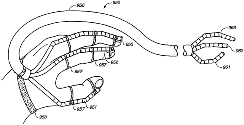
ring finger, and pinky. In the variation shown in Figure 9C, mechanism 950
includes three
articulating mechanisms operable by movement of a user's thumb, index, and
middle
fingers. As can be seen, proximal ends 951, 952 and 953 are affixed to a
user's thumb, index
finger and middle finger, respectively, by straps 957. The mechanism is
further secured to
the user's hand by strap 958 which secures the proximal end of spacer element
956 to the
user's wrist. Movement of the user's thumb, index finger, and middle finger
causes
corresponding movement of distal ends 961, 962 and 963, respectively. Such
variations may
be advantageous in various surgical situations where gross manipulation of
tissue or organs
18
CA 02588286 2012-08-03
is required. In this as well as other variations, a protective pliable sheath
can be extended
over the mechanism to avoid potential damage to tissue from individual links
or cables.
[0092] In yet further variations, the articulating mechanisms or
combinations of
articulating mechanisms described above that mimic finger movement (also
generally
referred to herein as hand-actuated devices) and that include a user hand
interface at the
proximal end of the device for removably securing a digit of a human hand, may
be further
modified such that the user hand interface is also configured to removably
engage with the
palm (ventral surface) of the hand. The interface generally includes two
portions, a finger
portion for actuating movement and releasably securing one or more fingers to
the interface,
and a handle portion which partially abuts the palm and which provides another
surface for
releasably securing a user's hand and fingers. The ergonomics of this device
configuration is
particularly desirable since a user's hand may be quickly engaged and
disengaged from the
device. The ability to quickly and easily engage or disengage one's hand from
the device
may be particularly advantageous in, e.g., surgical settings where surgeons
typically need to
swap surgical tools rapidly. Importantly, although the devices are generally
adapted for use
by a human hand, and typically include three mechanisms to accommodate the
index finger,
middle finger, and thumb of the hand, the number of articulating mechanisms
that may be
included is not so limited, and may include as many mechanism as a user can
control at
once.
[0093] The distal end of the hand-actuated devices usually includes an
effector portion
that generally mimics the structure and movement of human fingers and which is
remotely
actuated by corresponding movements at the finger portion of the interface.
The effector
portion is typically configured to provide such gross movements as gripping
and pinching,
but also provides for finer finger movements oftentimes required, e.g., for
fine tissue
manipulation. Thus, in surgical applications, the effector may be used to
clamp, provide
traction, dissect, debride, suture, or otherwise manipulate body tissues.
[0094] Anatomically, human fingers include bones called phalanges. The
index finger,
middle finger, ring finger, and pinky have three phalanges, commonly referred
to as the
proximal phalanx, middle phalanx, and distal phalanx. The thumb includes only
two
phalanges, a proximal phalanx and a distal phalanx. Movement of the phalanges
are
controlled by finger joints that join the head of one phalanx with the base of
the more distal
one. Joints at the base of the proximal phalanx (that connect the proximal
phalanx to bones
of the hand) are metacarpophalangeal (MCP) joints that typically allow
flexion, extension,
19
CA 02588286 2012-08-03
abduction, adduction, and circumduction (movement in two degrees of freedom)
of the
proximal phalanx. Interphalangeal (IP) joints, on the other hand, which join
the distal
phalanx to the middle phalanx and/or the middle phalanx to the proximal
phalanx, are
typically uniaxial hinge joints that petinit only flexion and extension
(movement in a single
degree of freedom).
[0095] The hand-actuated devices of this invention are typically made from
links
adapted in such a way to generally correspond to the anatomical structure of
human fingers
and generally parallel the range of motion of human finger joints, but can
also be configured
to provide joint movement in any desired degree of freedom. For example, links
can be
dimensioned and grouped together so that they look and work similar to human
fingers and
finger joints. In that vein, links adapted to correspond to phalanges would
be, e.g., longer
than links used as part of the finger joints (MCP and IP joints). Essentially,
a device
including components that correspond to the general anatomic structure of
human fingers
and which generally parallel the function of human finger joints would provide
much of the
manual dexterity generally associated with the human hand.
[0096] The links representative of phalanges may be of any dimension, so
long as they
are capable of functioning similar to human phalanges, but are typically
longer than other
links, as mentioned above, and will accordingly be referred to herein as
"elongate links".
The length of an elongate link may range from a less than a millimeter to a
few centimeters,
and in some non-medical applications, even several inches. For general
surgical use, the
length of elongate links corresponding to proximal phalanges may be about 22
mm, for
middle phalanges about 17 mm, and for distal phalanges about 15 mm. Elongate
links at the
proximal end of the device will be generally referred to as "finger links" and
those at the
distal end of the device will be referred to as "effector links".
[0097] The elongate links can take any form that can provide functionality
similar to a
human phalanx may be used. For example, if desired, the elongate links can be
made
flexible. The diameter of the elongate links may also vary, depending on
factors such as the
finger that the link is being associated with (e.g., thumb, index finger, or
middle finger) and
the device application, but will typically be from about 1 mm to about 20 mm,
or more than
20 mm. The diameter of a smaller elongate link may be about 1 mm to about 3
mm, for a
mid-range elongate link about 3 mm to about 7 mm, and for a larger elongate
link about 7
mm to about 10 mm or more.
CA 02588286 2012-08-03
100981 The elongate links may be made from any biocompatible material as
previously
mentioned for links, including, but not limited to, stainless steel; titanium;
tantalum; and any
of their alloys; and polymers, e.g., acrylonitrile-butadiene-styrene (ABS)
terpolymer,
Dekin() acetal homapolymers and copolymers, polycarbonate, polyethylene or
copolymers
thereof, polyethylene terephthalate or copolymers thereof, nylon, silicone,
polyurethanes,
fluoropolymers, poly (vinylchloride); and combinations thereof, or any other
suitable
material known in the art. The elongate links may also be variously textured
to enhance their
gripping or traction ability, as will be apparent to one of skill in the art.
The elongate links
themselves can be textured or a textured material can be applied to the
elongate links. In
certain variations, the textured material can include tractive surfaces, as
disclosed in U.S.
6,821,284.
100991 As previously described, phalanges are joined to one another by
human finger
joints, i.e., the DIP, PIP, and MCP joints. In a similar fashion, elongate
links are connected
by joints in the mechanism. As used herein, "joint" refers to discrete links
or a discrete
combination of links capable of having the range of motion of a DIP, PIP, or
MCP joint. At
the proximal end of the mechanism, the joint corresponding to an MCP joint
will be
generally referred to as the "base joint" and the joints corresponding to DIP
and PIP joints
will be generally referred to as "finger joints". At the distal end of the
mechanism, the joint
corresponding to the MCP joint will be generally referred to as the "effector
base joint" and
the joints corresponding to DIP and PIP joints will be generally referred to
as "effector
joints". The joints may be made from any biocompatible material similar to
that used for
elongate links, as previously described.
[00100] The hand-actuated devices may be formed from a plurality of
individually
attached elongate links and joints or from elongate links and joints formed
integrally with
one another. Furthermore, the links and link combinations used as elongate
links or joints
include those described herein, as well as other suitable links and link
combinations,
including, but not limited to, those disclosed in U.S. Application Serial No.
10/928,479, filed
on August 26, 2004, U.S. Application Serial No. 10/948,911, filed on September
24, 2004,
and U.S. Application Serial No. 10/997,372, filed November 23, 2004. Links
that are
designed to adjust for cable bias, including those described in U.S.
Application Serial Nos.
10/928,479 and 10/948,911, are also useful. In order to provide for increased
rigidity of the
articulating mechanism and hand-actuated devices when manipulated, active
links are
typically fully constrained so as to resist movement due to laterally applied
forces, as is
21
CA 02588286 2012-08-03
described in U.S. Application Serial Nos. 10/928,479 and 10/948,911. The use
of fully
constrained links helps to preserve the integrity of the desired shape formed
at the distal or
proximal end of a manipulated mechanism when in use, and allows force to be
distributed
across the desired shape. Spacer links on the other hand are typically
unconstrained. The
provision of spacer links decreases the rigidity of the proximal or distal end
in those areas
that contain such spacer links or flexible segments, which can be desirable,
e.g., when
navigating through or around sensitive or fragile anatomical structures.
1001011 As
previously described, articulating mechanisms of this invention include links
at a proximal and distal end of the mechanism. The proximal and distal links
form discrete
pairs and are connected to each other by cable sets so that movement of one
link of a pair
causes corresponding movement of the other link in the pair. In the same
fashion, hand-
actuated devices of this invention include articulating mechanisms having a
plurality of
elongate links that form members of discrete pairs. The elongate links form a
proximal end,
or "finger portion", and distal end, or "effector portion", with one elongate
link of each pair
being situated at the finger portion end, and the other elongate link at the
effector portion
end. Cable sets run through the joints and connect the elongate links of a
discrete pair to one
another so that movement of one elongate link of a pair causes a corresponding
movement of
the other elongate link in the pair, independent of movement of other pairs of
elongate links.
1001021 The one to one correspondence of movement of elongate links may also
be
extrapolated to joints. As further described below, articulation of the
effector joints may be
generally achieved by articulation of a base joint and finger joints at the
proximal end of the
device or may be achieved by actuation of a finger slide. In some
applications, it may be
desirable to scale movement of effector links and joints, to either increase
or decrease the
movement produced at the distal end relative to the corresponding movement at
the proximal
end, examples of which will be also be provided below. As previously
mentioned,
proportional scaling of movement in the articulating mechanisms can in general
be
accomplished by the inclusion of additional spacer links. Proportional scaling
of movement
in the articulating mechanisms can also be accomplished in general by
increasing or
decreasing the cable channel pattern radius in the links, at either the
proximal or distal end of
the mechanism, as is further described in pending and commonly owned U.S.
Application
No. 10/948,911. For example, if the radial distance of cables from central
axis of links of the
proximal end is greater than that in the distal end, the degree of bending or
flex of the distal
end will be proportionally greater than that of the proximal end. The result
is that smaller
22
CA 02588286 2012-08-03
degree of movement at the proximal end will produce a greater degree of
movement at the
distal end. Alternatively, if the cable radial distance of links of the
proximal end is less than
that in the distal end, the degree of bending or flex of the distal end will
be proportionally
less than that of the proximal end, such that movement of the proximal end
will be
exaggerated relative to the distal end. Proportional scaling of movement will
also typically
produce scaling of force.
[00103] Figures 14-17 depict a variation of a hand-actuated device in which
articulation
of the effector joints may be generally achieved by articulation of a base
joint and finger
joints at the proximal end of the device. In Figure 14, the hand-actuated
device 1700 has a
proximal end 1711 and a distal end 1721. A user interface 1713 at the proximal
end 1711
includes a finger portion 1712 and a handle portion 1717. The finger portion
1712 actuates
movement at distal end 1701 and releasably secures one or more fingers to the
interface
1713. Handle portion 1717 partially abuts the palm and provides another
surface for
releasably securing a user's hand and fingers. Typically, a user's thumb,
index finger, and
middle fingers will be releasably secured to finger portion 1712, but any
combination of
fingers may be releasably secured. In Figure 14, finger portion 1712 is
adapted to releasably
secure a user's index finger, middle finger, and thumb in an index finger
portion 1714,
middle finger portion 1715, and thumb portion 1716, respectively.
[00104] In one variation, a user's fingers may be releasable secured or
releasably engaged
to finger portion 1712 by finger loops 1509, as shown in Figure 15.
Specifically, a user's
index finger, middle finger, and thumb may be releasable secured to an index
finger portion
1714, middle finger portion 1715, and thumb portion 1716, respectively.
[00105] An enlarged view of an index finger portion is shown in Figure 16.
Finger loops
1709 may be constructed from the same materials as the elongate links
described above, and
are attached to finger links 1707A, 1707B, and 1707C by techniques well known
in the art,
such as, but not limited to, fastening, e.g., such as with a mechanical
fastener, welding and
gluing. Extending between finger links 1707A and 1707B is distal finger joint
1708A, which
is configured to have a range of motion similar to a DIP joint. Extending
between finger
links 1707B and 1707C is another distal finger joint 1708B, which is
configured to have a
range of motion similar to a PIP joint. Finger link 1707C is coupled to handle
portion 1717
by proximal base joint 1708C, which is configured to have a range of motion
similar to a
MCP joint. The particular structure of the joints will be addressed further
below.
23
CA 02588286 2012-08-03
[00106] The hand-actuated mechanisms of this and other variations also include
an
effector portion for remote manipulation of, e.g., instruments, tools, or body
tissues. In one
variation, shown in Figure 17, effector portion 1701 is shown to include three
effectors,
1702, 1703, and 1704, but if desired, the device can be equipped with more or
less than three
effectors. Similar to finger portions, effectors also include elongate links
and joints. Elongate
links and joints in the effector portion are generally referred to as
"effector links" and
"effector joints" respectively, and are also adapted in such a way to mimic
human
finger/hand movement. Effector links will typically correspond to phalanges,
and the range
of motion of effector joints will usually parallel that of DIP, PIP, or MCP
joints. For
example, in Figure 17, effector links 1705 A, 1705B, and 1705C are configured
to
correspond to a distal phalanx, middle phalanx, and proximal phalanx,
respectively, and
effector joints 1706A, 1706B, and 1706C are adapted to parallel the function
or range of
motion of the DIP, PIP, and MCP joints, respectively.
[00107] In operation, as shown in Figures 15 and 17, movement of a user's
fingers, e.g.,
an index finger, middle finger, and thumb, from an open (Figure 15) position
to a closed,
grasping position (Figure 17), correspondingly moves finger links 1707A,
1707B, 1707C
and finger joints 1708A, 1708B and effector base joint 1708C because the
user's fingers are
releasably secured to finger loops 1709 that are also attached to finger links
1707A, 1707B,
and 1707C. Cables (not shown) running through the finger links 1707A, 1707B,
and 1707C,
finger joints 1708A and 1708B, effector base joint 1708C, handle portion 1717,
shaft 1710,
and effector palm 1711, are actuated by the user's finger movement to produce
a
corresponding movement of effector portion 1701. Specifically, movement of
finger joint
1708A causes a corresponding articulation of effector joint 1706A, movement of
finger joint
1708B causes a corresponding articulation of effector joint 1706B, and
movement of base
joint 1708C causes a corresponding articulation of effector base joint 1706C.
Mirrored
movement at the effector portion 1701 may be generally achieved by rotating
the cables
approximately 180 as they travel through the handle portion 1717, or shaft
1710, or effector
palm 1711. Mirrored movement may be more intuitive and also desirable in some
instances
because it allows the effector portion to, e.g., close when a user's fingers
are closed, or move
right when a user's finger moves right, or move left when a user's finger
moves left.
Alternatively, inverted movement may be generally achieved by not rotating the
cables. In
some instances, it may be desirable to provide a combination of mirrored
motion and
inverted motion in the effector portion.
24
CA 02588286 2012-08-03
[00108] Although only a thumb, index finger, and middle finger portions are
depicted in
the user interfaces of Figures 14, 15, and 17, as well as in other figures,
the invention is not
so limited. Depending on such factors as the intended use or user preference,
the interface
may be configured to include a finger portion for releasably securing any
number of fingers.
In addition, the finger portions may be arranged on the handle portion as
illustrated in
Figures 14-17, but may also be varied to accommodate other arrangements and
positions, so
long as adequate actuation of the effector portion may be achieved.
[00109] Figures 18-20 depict another variation of a hand-actuated device in
which
articulation of the effector joints may be generally achieved by actuation of
finger slides. In
this variation, as shown in Figure 18, hand-actuated device 1800 has a
proximal end 1801
and a distal end 1821. A user interface 1803 at the proximal end 1801 includes
a finger
portion 1804 and a handle portion 1805. The finger portion 1804 includes
finger slides 1806
for actuating movement at the distal end 1821 and releasably securing one or
more fingers to
the interface 1803. Handle portion 1805 partially abuts the palm and provides
another
surface for releasably securing a user's hand and fingers.
[00110] Distal portion 1802 includes an effector portion 1807 having
effectors 1808,
1809, and 1810. Effectors are made up of effector links and effector joints as
previously
described. For example, in Figure 18, effector 1808 includes effector links
1811A, 1811B,
and 1811C, and effector joints 1812A, 1812B, and 1812C. In particular, the
function of
effector joint 1812A parallels a DIP joint, effector joint 1812B parallels a
PIP joint, and
effector base joint 1812C parallels a MCP joint.
[00111] The user interface 1803 of this variation includes finger slides
1806 in addition to
a base joint 1813 to actuate movement of effectors 1808, 1809, and 1810. In
this as well as
other variations, movement of base joint 1813 mimics MCP joint movement and is
capable
of flexion, extension, abduction, adduction, and circumduction.
[00112] In operation, as shown in Figures 19 and 20, movement of a user's
fingers, e.g.,
an index finger, middle finger, and thumb, from an open (Figure 19) position
to a closed,
grasping position (Figure 20), actuates finger slides 1806. Using the index
finger as an
example, actuation of index finger slide 1806 correspondingly articulates
effector joints
1812A, 1812B, as described further below. Articulation of base joint 1813,
correspondingly
articulates effector base joint 1812 C in the effector portion 1807, in the
same fashion as
described for the base joint in the finger loop variation. Cables (not shown)
running from
finger slides 1806 and base joint 1813 through handle portion 1805, shaft
1815, and effector
CA 02588286 2012-08-03
palm 1816, are actuated by the user's finger movement to produce a
corresponding
movement of the effector portion 1807. Mirrored movement at the effector
portion 1807 may
be generally achieved by rotating the cables approximately 180 as they travel
through
handle portion 1805, shaft 1815, and effector palm 1816. The shaft can be of
varying length
and can be rigid or flexible, as circumstances warrant.
[00113] As briefly mentioned above, the arrangement of the finger portions on
the handle
portion of the interface may vary to improve ergonomics or depending on
factors such as
user preference or the type of procedure involved. For example, as shown in
Figure 21, the
thumb slide 2101 is mated to the handle portion 2102 at a position different
from that shown
in Figures 14-20. In a particularly ergonomic configuration, as illustrated in
Figure 21, the
position of the thumb slide 2101 is lower than the index finger slide 2103 and
middle finger
slide 2104, and in some instances, also lies posterior to these slides.
[00114] The general configuration of the finger slides may vary depending on
many user-
associated factors such as ergonomics and user preference, but are usually
configured to
include a holder, a slider, a transmission rod, and a pulley lever, such that
translational
movement of the holder produces rotational movement of the pulley lever, which
in turn
moves connecting cables to actuate effector joints and links.
[00115] In the variation illustrated in Figure 22, finger slide 2200
includes a housing
2201, a track 2202 along housing 2201, a holder 2203, a transmission rod 2204,
a pulley
lever 2205, and a slider 2206. Slider 2206 is coupled to housing 2201 by dowel
2211 placed
through slider 2206 and track 2202 to prevent slider 2206 from rotating with
respect to
housing 2201. Holder 2203 is coupled to slider 2206 at pivotable hinge 2207
that
accommodates finger flexion and extension. The tip of a digit may be placed in
holder 2203,
and upon flexion or extension of the PIP and DIP joints, movement of the
holder 2203
causes translational movement of slide 2206 along track 2202. This slide
movement
translates translational movement of the transmission rod 2204 into rotational
movement of
pulley lever 2205, thereby pulling cables (not shown) connected to pulley
lever 2205 to
cause movement of the effector portion as further described below. The holder
2203 depicted
in Figure 27 has a top plate 2208 and bottom plate 2209 for removably securing
the fingertip
of a user. The holder configurations of this invention, however, not only
include the structure
shown in Figure 27, but also contemplate loop-type structures 2310 (Figure
23), or any
configuration suitable for removably securing the fingertip of a user for
actuation of the
device. In this and other variations, base joint 2210 extends from housing
2201 and may be
26
CA 02588286 2012-08-03
rigidly fixed to housing 2201 or formed integrally therewith. As previously
described, joints
such as base joint 2210 are configured to function similar to MCP joints
having at least
movement in two degrees of freedom. Finger slide actuation corresponds to
articulation of
DIP and PIP joints which are generally known to move in a single degree of
freedom.
[00116] Another finger slide variation is shown in Figures 23 and 24, and
in Figures 18-
21. In this variation, finger slide 1806 includes a housing 2301 with slide
pins 2302, a curved
slide 2303, a transmission rod 2304, a pulley lever 2307, a holder 2310, and
pulleys (not
shown). The provision of curved slide 2303 is particularly ergonomic because
in operation
the overall motion of the finger slide takes a curved path that mimics the
path a user's
fingertips make when the PIP and DIP joints are bent. Furthermore, use of this
curved slide
path more accurately mimics human finger movement because with this
configuration, a
user's DIP and PIP joints can be articulated without moving the MCP joint. For
example,
referring back to Figure 20, actuation of effector joints 1812A and 1812B
could easily occur
independently of actuation of effector base joint 1812C. The curve of slide
2303 may be
adapted to be a circular arc, ellipse, parabola, and the like, in order to
achieve this motion.
[00117] With respect to other features of finger slide 1806, slide pins
2302 insert into
track 2308 to couple curved slide 2303 to housing 2301. Pulley lever 2307 is
pivotably
connected to housing 2301 by a first dowel 2309. A transmission rod 2304
having a
proximal end 2305 and a distal end 2306 operably connects pulley lever 2307 to
holder
2310. A second dowel 2311 couples transmission rod proximal end 2305 to pulley
lever
2307. At distal end 2306, transmission rod 2304 is pivotably connected to
curved slide 2303
by a third dowel (not shown). In Figure 23, a base joint 1813 that is rigidly
fixed to housing
2301 is also shown.
[00118] In Figure 24, the relationship of additional finger slide elements
to each other is
more clearly depicted. As shown in Figure 24, finger slide 1806 includes a
curved slide 2303
having a distal end 2313. Distal end 2313 is fixedly connected to bracket
2314. Plate 2315
has a cylindrical opening 2316 that receives mandrel 2317, such that plate
2315 can rotate
about mandrel 2317. Mandrel 2317 is pivotally coupled to bracket 2314 by dowel
2318.
Plate 2315 can thus both pivot and rotate relative to bracket 2314, i.e., it
can pivot about
dowel 2318 as well as rotate relative to mandrel 2317. Holder 2310 is secured
to plate 2315
and thus can also pivot and rotate with respect to bracket 2314. This finger
slide
configuration is particularly ergonomic because it accommodates natural finger
movement
when the fingers are abducted. The ability of the finger holder to rotate
relative to the slide,
27
CA 02588286 2012-08-03
in particular, is advantageous as it more readily accommodates a combined
flexion and
abduction movement between fingers during which the fingertips naturally
rotate slightly
relative to one another.
[00119] The finger slide of Figure 23 also includes cables for actuating
movement of the
effector portion as shown in the cross-section taken along line B-B in Figure
25 and in
Figure 26. Cables 2503 and 2504 wrap around pulley 2317 and terminate in
pulley lever
2307. Cables 2501 and 2502 wrap around pulley 2318 on the opposite side of
pulley lever
2307 and similarly terminate in pulley lever 2307. In operation, flexion or
extension of a
user's finger at the DIP and PIP joints, e.g., an index finger, secured to the
finger slide,
causes a rotational movement of pulley lever 2307 which thereby freely pulls
cables 2501
and 2502 about pulley 2318, and freely pulls cables 2503 and 2504 about pulley
2317. More
specifically, when a user's index finger is flexed at the DIP and PIP joints,
cable 2501 is
pulled about pulley 2318 and cable 2503 is pulled about pulley 2317. When a
user's index
finger is extended at the DIP and PIP joints, cable 2502 is pulled about
pulley 2318 and
cable 2504 is pulled about pulley 2317. Cables 2501, 2502, 2503, and 2504 then
pass
through channels 2604 in base joint 1813 to articulate movement of effector
joints (e.g.,
joints 1812A and 1812B in Figure 30) as further described below.
[00120] The pulleys may be configured to rotate about dowel 2309 or may be
fixedly
attached to pulley lever 2307, and generally have diameters that vary from one
another.
[00121] In some instances, it may be desirable to scale movement of the
effectors in
relation to movement occurring at the user interface. Typically, pulley
diameters are selected
so that the amount of cable pulled for a given rotation is equal to the cable
that would be
pulled if an articulating link were substituted in place of the pulley. Thus,
because cables that
actuate a most-distal effector link (e.g., 1811A in Figure 20) usually travels
farther than
cables that actuate another distal effector link (e.g., 1811B in Figure 20),
the diameter of the
pulley that controls the most distal effector link must be larger than that of
the pulley that
controls the distal effector link. For example, in Figure 25, pulley 2318 is
shown to have a
diameter approximately twice that of pulley 2317. Scaling of effector movement
can be
further adjusted by varying the pulley diameters while retaining the same
ratio of the pulley
diameters relative to one another and/or varying the ratio of the pulley
diameters relative to
one another. In addition, although the pulleys in Figures 25-26 are circular,
other pulley
shapes may be employed to adjust movement of the effector joints. For example,
a cam
shape may be used to articulate an effector joint in a non-linear fashion.
28
CA 02588286 2012-08-03
[00122] Referring to Figure 26, another way to scale effector movement is to
adjust the
position of transmission rod 2304 along the length of pulley lever 2307 by
lifting distal end
of transmission rod 2305 closer to pulley 2317 such that dowel 2323 inserts
into one of
dowel apertures 2317. Effector movements will be scaled down as distal end
2305 is
positioned closer to pulley 2505. Other ways to scale movement of the
effectors include, but
are not limited to, the inclusion of additional spacer links and/or varying
the cable channel
pattern radius in the links, as previously discussed. In some instances, e.g.,
in industrial
applications, reverse scaling may be desirable.
[00123] Movement of base joint 1813 is actuated by the user's fingers. As
previously
described, movement of base joint 1813 results in a corresponding movement at
an effector
base joint (e.g., 1812C in Figure 20). The cables used to connect base joint
1813 to an
effector base joint, cables 2601, 2602, and 2603, terminate as shown on base
joint 2813 in
Figure 26. Cable termination at the effector portion will be further described
below.
[00124] All cables leaving the finger portion of a user interface travel
through a handle
portion, shaft, and an effector palm before terminating at an effector link.
As mentioned
above, in order for movement to be mirrored at the distal end of the device,
cables traveling
from the proximal end are generally rotated approximately 180 prior to
terminating at the
distal end. However, in certain applications, because a combination of
mirrored and inverted
movement may be desired, all cables do not necessarily have to be rotated. In
addition, in
single degree of freedom joints, e.g., a joint corresponding to a DIP or PIP
joint, the cables
do not have to be rotated 180 in order to provide mirrored movement. The
cables simply
need to be moved to the other side of the pivot or hinge on one link of the
pair relative to
cable position on the other link of the pair.
[00125] Figure 27 depicts cable rotation through handle portion 1805 by noting
the entry
and exit points of cables in handle portion 1805. In Figure 27, cables enter
handle portion
1805 in the general pattern shown at a first area 2703. For example cable 2602
is shown to
enter first area 2703 at approximately the 2 o'clock position, and 2603 at the
5 o'clock
position. Upon exit at a second area 2702, a different cable pattern is seen.
Instead of exiting
at the 2 o'clock position, cable 2602 exits at approximately the 8 o'clock
position, and for
cable 2603, instead of exiting at the 5 o'clock position, it exits at
approximately the 11
o'clock position. A rotation of 180 is needed only if mirrored movement is
desired.
Otherwise, cables may be rotated in any manner to suit the intended use of the
device.
29
CA 02588286 2012-08-03
[00126] The handle portion 2802 of the user hand interface may be a molded
handle, as
shown in Figure 28, with channels or tubes 2801 for routing cables. In this
variation, instead
of rotating cables, the channels may be rotated or crossed to effect mirrored
or inverted
movement. In another variation, as shown in Figure 29, the handle portion 2901
may be
hollow and include a pulley 2902 for alignment and routing of cables 2903. The
cables 2903
in this variation can be rotated (crossed) either before reaching pulley 2902,
or after travel
around pulley 2902. Materials that may be used to make the molded or hollow
handles of
this invention include those previously described for elongate links, as well
as others that
may be suitable for making medical devices.
[00127] The effector portion of the device typically includes three
effectors that
correspond to a user's index finger, middle finger, and thumb, but any number
of effectors
may be included. As generally described, cables traveling from the user
interface variously
terminate at effector links to actuate effector movement. An understanding of
joint
articulation using a finger slide may be better obtained by viewing the cable
termination
points shown in Figure 30 in conjunction with Figures 18-20. The effector
portion depicted
in Figure 30 represents effector portion 1807 in Figures 18-20. Although the
general
structure and operation of effectors in the finger slide variation are being
described, it is
understood that this structure and operation also applies to the interface
variation having
finger loops.
1001281 In Figure 30, effector 1808 corresponds to a user's index finger,
and is generally
configured to include an effector base joint 1812C, two effector joints 1812A
and 1812B,
and effector links 1811A, 1811B, and 1811C. Effector link 1811C corresponds to
the
proximal phalanx of an index finger; effector link 1811B corresponds to the
middle phalanx
of an index finger; and effector link 1811A corresponds to the distal phalanx
of an index
finger. Similarly, effector base joint 1812C corresponds to a MCP joint
capable of
movement in at least two degrees of freedom, effector joint 1812B corresponds
to a PIP joint
capable of movement in a single degree of freedom, and effector joint 1812A
corresponds to
a DIP joint, also capable of movement in a single degree of freedom. As
depicted in Figure
34, effector link 1811B, which is representative, is formed by securing links
3101 to the ends
of a tube, although other methods of forming the effector links will be
readily apparent.
[00129] Cables from the handle portion of the device are received through
shaft (not
shown) and are routed to the appropriate effector by effector palm 1816.
Effectors emerge
from effector palm 1816, as shown in Figure 30 and other figures, that extends
from the
CA 02588286 2012-08-03
shaft. However, if desired, the effectors may be adapted to emerge from
different points
along the shaft or effector palm 1816 to form, e.g., a staggered or more
spread out effector
configuration. In this manner, a more or less hand-like effector portion can
be made.
Typically, cables 2501, 2502, 2503, and 2504 from the slider which actuate
movement of
effector joints 1812A and 1812B, terminate at one of the two effector links
1811A and
1811B. For example, as more clearly shown in Figure 31A, cables 2501 and 2502
which are
pulled around the larger pulley, and which articulate movement of effector
joint 1812A,
terminate in distal-most effector link 1811A. Cables 2503 and 2504 which are
pulled around
the smaller pulley, and which articulate effector joint 1812A, terminate in
effector link
1811B, as shown in Figure 31B. Likewise, cables 2601, 2602, and 2603
originating from
base joint (1904 in Figure 20) and which articulate movement of effector base
joint 1812C,
generally terminate at effector link 1811C, as depicted in Figure 31C.
[00130] Effector joints 1812A-1812C are typically configured to have a range
of motion
that mimics the range of motion of MCP, PIP, and DIP joints, respectively. For
example,
effector base joint 1812C which corresponds to an MCP joint, is typically
equipped to move
in at least two degrees of freedom by including, e.g., two or more links 3105
each having a
rib 3106 extending from the diameter of one surface of the link and having
channels 3104
running across the diameter of their opposite surface. Channels 3104 are
adapted to
pivotably engage rib 3106 along the entire length of the channel, such that
two links can
pivot relative to one another about the axis of the channel. In effector base
joint 1812C, the
two links are positioned with their respective ribs oriented orthogonal to one
another and
with the rib of the most proximal link engaging a similar channel provided in
effector palm
1816, in order to provide movement in two degrees of freedom. Distal effector
joints 1812A
and 1812B generally only require movement in a single degree of freedom.
Figure 33 is
representative of effector base link 1812C also shown in Figures 30 and 31C.
Another
representative joint structure providing a single degree of freedom is
depicted in Figures
31A-31B, and Figure 32 and includes links 3101 having a rib 3102 extending
from the
diameter of one surface of the link and having a channel 3103 aligned with the
extending rib
on its other side. Channels 3103 are adapted to pivotably engage rib 3102
along the entire
length of the channel, such that two links can pivot relative to one another
about the axis of
the channel, to provide a single degree of freedom.
[00131] Importantly, the finger portion of the interfaces described above
may be
configured to include a combination of finger slides and finger loops for
articulation of
31
CA 02588286 2012-08-03
effector joints. For example, because thumb joints can generally move somewhat
independently from one another, a finger loop type finger portion may provide
more accurate
mimicking of human thumb joint movement at the effector. This is because
finger loop input
control allows for independent control of distal effector link movement, in
contrast to finger
slides which only allows coupled control of distal effector link movement. On
the other
hand, when DIP and PIP joints of fingers such as the index finger, middle
finger, and ring
finger, are articulated, they usually flex or extend together. Accordingly, it
may be more
suitable for finger slides to actuate effector movement for these fingers.
[00132] It
is also understood that the hand-actuated devices may also adopt
configurations
that differ from the human hand. For example, in certain surgical
applications, it may be desirable to shape the effector portion in such a way
that it becomes a
tool with functionality other than that of gripping of the hand.
[00133] In yet another variation, the articulating mechanism may be used for
the
endoscopic treatment of atrial fibrillation. In particular, the articulating
mechanism of the
invention can be adapted to facilitate the creation of ablative lesions in
heart tissue, which
has been demonstrated to be effective in treating atrial fibrillation, as
described e.g. by Cox,
J.L. (2000). "Minimally Invasive Maze-Ill Procedure," Operative Techniques in
Thoracic
and Cardiovascular Surgery Vol. 5(1):79-92; Simha et al. (2001). "The
Electrocautery Maze
- How I Do It," The Heart Surgery Forum Vol. 4(4):340-345; and Prasad et al.
(2001).
"Epicardial Ablation on the Beating Heart; Progress Towards an Off-Pump Maze
Procedure," The Heart Surgery Forum Vol. 5(2):100-104; and as described in
U.S. Patent
No. 6,161,543 to Cox et al. Such procedures can include epicardial or
endocardial ablation,
and many such procedures require accessing the posterior of the patient's
heart, which can
be difficult. The articulating mechanism of the invention can be configured
with an ablative
element, and together with its ability to form complex geometries; the
mechanism can be
readily navigated through the surrounding anatomy of the heart and easily
positioned at
various locations in or on the posterior of the heart to facilitate such
ablation therapy.
[00134] Articulating mechanism 131 shown in Figure 12A includes ablative
element 125
connected to an electromagnetic energy source (not shown), such as an energy
source which
generated energy in radiofrequency (RF) or microwave frequency ranges. Such
ablative
elements are well known in the art, including those generally described in
U.S. 6,471,696.
The ablative element is mounted to links on the distal end 141 of the
mechanism by way of
attachment member 134 which is fittingly engaged with in channels 144 of links
142. The
32
CA 02588286 2012-08-03
ablative element includes an insulated portion 127, typically formed of a
thermoplastic
elastomer, with longitudinally extending antenna or wire 129 for transmitting
energy into
tissue disposed therein. Other antenna or wire geometries, including helical
coils, printed
circuits, and the like are equally effective. Insulated conducting leads 136
and 137 are
provided for connecting the energy source to the antenna or wire in a
monopolar
configuration. Bipolar configurations are also contemplated. Additional
connectors 138 and
139 to the ablative element are also provided and can function in a variety of
capacities, such
as providing temperature or other sensors or probes, or to deliver a cooling
medium to the
element to cool the surrounding tissue and prevent extensive tissue damage, as
is described,
e.g., in U.S. Patent Application Publication No. US 2003/0078644 to Phan.
[00135] Figure 12B shows another variation of the articulating mechanism of
the present
invention configured for ablation. In this variation, articulating mechanism
133, which is
configured for bipolar use, includes distal end 143 having distal links 152
that contain
opposing electrodes 159. The opposing electrodes are separated by channel 164.
Insulated
conducting leads, such as leads 166 and 167, connect each pair of electrodes
to the energy
source (not shown). When energized, energy is transmitted across the electrode
pairs,
creating ablative lesions in the surrounding tissue. Again, additional
connections 168 and
169 are also provided to provide additional functions, including probes,
sensors, and cooling
fluids.
[00136] While the above variations use ablative elements that rely on
electromagnetic
energy, articulating mechanisms according to the invention can also be readily
adapted to
incorporate other methods of ablation known in the art. For example, the
ablative element
could be a cryogenic or ultrasonic probe, or ablative elements that use laser
energy, or other
known ablative techniques.
[00137] Epicardial ablative lesions can be created as shown in the example
depicted in
Figures 13A-13F. Access to the posterior of a patient's heart 929 by
articulating mechanism
131 may be initially made through, e.g., a thoracotomy, mini-thoracotomy, or
trocar port
(e.g., a 5-10 mm port), placed in the anterior chest wall of a patient. The
spacer element (not
shown) of the articulating mechanism may serve the purpose of a fulcrum at the
port. As the
surgeon bends the proximal links that are outside of the patient, the distal
links inside the
patient mimic the curvature of the outside links in a reciprocal fashion, in
order to wrap
around the superior vena cava 933 (13A) and continue to surround and the
pulmonary veins
935 (13B) as the articulating mechanism is simultaneously advanced. Once in
position, as
33
CA 02588286 2012-08-03
shown in Figure 13B, the ablative element on the distal end of the
articulating mechanism
can then be activated to create a lesion, and as depicted here in particular,
pulmonary
encircling lesion 943 (Figure 13C). In Figures 13D and 13E the articulating
mechanism is
shown being repositioned to extend downward from the pulmonary veins 935 to
create a
lesion 939 down to the mitral valve annulus that connects to prior-formed
pulmonary
encircling lesion 943 (Figure 13F).
[00138] The invention also contemplates kits for providing various
articulating
mechanisms and associated accessories. For example, kits containing
articulating
mechanisms having different lengths, different segment diameters, and/or
different types of
surgical instruments, or different types of locking rods or malleable
coverings may be
provided. The kits may be tailored for specific procedures, e.g., endoscopy,
retraction, or
catheter placement, and/or for particular patient populations, e.g., pediatric
or adult.
1001391 The scope of the claims should not be limited by particular
embodiments set
forth herein, but should be construed in a manner consistent with the
description as a whole.
34