Note: Descriptions are shown in the official language in which they were submitted.
CA 02588686 2007-05-15
- 1 -
Improvements in or Relating to Dispensing Apparatus
This invention relates to dispensing apparatus having
integral dosage counting devices which require an axial
force for actuation.
It has been recognised that there is a need to provide
accurate information to a user of a dose-dispensing delivery
apparatus, such as a pressurised metered dose inhaler,
concerning the number of doses delivered from, or remaining
in, the dispensing apparatus. Without such information,
there is a danger that a user will forget how many doses
have been delivered and hence take a greater or fewer nurnber
of doses than are required. There is also a danger that a
user rnay be unaware that the dispensing coritainer of the
dispensing apparatus is empty or close to empty. This is
especiaily dangerous where the dispensirig apparatus is for
use in deli.1,Tering medicinal compounds for the treat.ment of
chronic or acute symptoms, for exarnple, as in the case of a
pressurised metered dose inhaler used for treating asthmatic
reactions.
It is known to provide a dispensing apparatus with a
dose counting device. Typically such dose counting devices
are triggered by movement of the di.spensing con~ainer
wherein the movement either directly or indirectly pr_ovi.des
the motive force for incrementing or decrementing the dose
counting device. One issue with mechanical dose counters is
that it is typically possible to remove the pressurised
d,,_spensing cont.ainer froin the apparatus, and in particular
from the counting mechanism. There is then the possibility
of actuating the pressurised dispensing contai.ner with i_t
removed fro_mõ the counting mechanism which ~7ould res,zlt ir.
the counting mechanism effectively under-counting the true
CA 02588686 2007-05-15
- 2 -
number of doses dispensed from the pressurised dispensing
contairier. One solution to this problem is to provide a
housing where the components of the housing envelop the
container in situ to directly prevent removal of the
container froin the apparatus. However, such designs
generally involve a larger number of housing components and
the housing requires a greater number of disassembly and
reassembly steps to initial load t.he pressurised dispensing
container into the housing.
Mechanical dose counters can also be difficult to
manufacture so that they work reliably. One problem is that
a mechanical dose counter typically requires a number of
components which must be accurately located relative to one
another during assembly to ensure that over-counting or
under-counting is not experienced. This can lead to a
requirement for very strict manufacturing tolerances which
can make manufacture expensive.
According to the present invention there is provided
dispensing apparatus for delivering metered doses of product
from a pressurised dispensing container comprising:
a housing comprising a body portion and a removable
mouthpiece, the body portion containing a dose counting
mechanism and a sleeve;
the body portion comprising an aperture through which
said pressurised disperising container can pass to be
received in the sleeve but through which the sleeve is
unable to pass such that the sleeve is retained within the
body portion;
the sleeve being located in the body portion such that
an upper end of said pressurised dispensing container when
received in the sleeve is accessible to allow actuation of
said pressurised dispensing container;
CA 02588686 2007-05-15
- 3 -
the apparatus comprising means for retaining said
pressurised dispensing container in the body portion.
Advantageously, a simple mechanism is provided for
retaining the pressurised dispensing container in the
apparatus to prevent incorrect counting by the dose counting
mechanism.
In one embodiment the means for retaining said
pressurised dispensing container in the body portion
comprises an opening in the body portion dimensioned to
receive a valve stem of said pressurised dispensing
container as an interference fit.
In this way the relatively tight fit between the valve
stem of the pressurised dispensing container and the body
portion helps to prevent easy removal of the pressurised
dispensing container from the body portion and hence also
prevents removal of the pressurised dispensing container
from the sleeve.
Preferably the opening in the body portion is a part of
a conduit for conveying a product dispensed from the valve
stem of the pressurised dispensing container to the
removable mouthpiece.
Preferably the apparatus further comprises a biasing
mechanism for urging, on insertion of said pressurised
dispensing container into the sleeve, said pressurised
dispensing container into positive engagement with the
sleeve. In this way, advantageously, there is a greater
degree of certainty when assembling a dispensing assembly
comprising the apparatus and a pressurised dispensing
container that the container has been properly seated into
the sleeve.
Preferably the biasing mechanisni urges an end face of a
body of the pressurised dispensing container into contact
CA 02588686 2007-05-15
- 9 -
with a basal face of the sleeve. This is advantageous in
ensuring not only that the pressurised dispensing container
is fully engaged into the sleeve on initial assembly but
also in helping to prevent mutual slippage or separation of
the pressurised dispensing container and the sleeve due to
the self-weight of the sleeve. In other words the biasing
affect of the biasing mechanism ensures face to face contact
between the basal face of the sleeve and the end face of the
body of the pressurised dispensing container whatever the
orientation of the assembly or stage of actuation of the
assembly.
The biasing mechanism may comprise one or more flexible
projections on the sleeve which are engagable with said
pressurised dispensing container.
The one or more flexible projections may depend from an
inner face of the sleeve and be directed towards a basal
face of the sleeve.
In one example the one or more flexible projections are
engagable in an undercut of said pressurised dispensing
container formed by a ferrule of said pressurised dispensing
container.
In another einbodiment, the means for retaining said
pressurised dispensing container in the body portion is
dimensioning the sleeve such that an interference fit is
produced between said pressurised dispensing container and
the sleeve.
In another embodiment the means for retaining said
pressurised dispensing container in the sleeve is a non-
return feature provided on the sleeve.
The non-return feature may comprise an inwardly
directed flange of the sleeve which allows said pressurised
dispensing container to pass thereby on insertion of said
CA 02588686 2007-05-15
- 5 -
pressurised dispensing container but acts to resist or
prevent subsequent withdrawal of said pressurised dispensing
container from said sleeve.
Alternatively, the non-return feature may comprise one
or more inwardly directed projections which allow said
pressurised dispensing container to pass thereby on
insertion of said pressurised dispensing container but acts
to resist or prevent subsequent withdrawal of said
pressurised dispensing container from said sleeve.
The flexible portion of the sleeve may comprise a
plurality of flexible fingers which are free at one end.
Alternatively, the flexible portion of the sleeve may
comprise a plurality of flexible fingers which are joined or
formed as cne with the sleeve at an upper and lower end of
the fingers.
Preferably in the above embodiments a surrounding of
the aperture of the body portion comprises one or more
scallops which allow access to said pressurised dispensing
container in order to actuate said pressurised dispensing
container, but which limit the available purchase on said
pressurised dispensing container. This is particularly
advantageous when used in combination with the use of an
interference fit between the valve stem of the pressurised
dispensing container and the body portion since the
available purchase on the container is insufficient for a
user to be able to apply enough force to overcome the
frictional engagement of the pressurised dispensing
container and the opening of the oiitlet conduit.
Preferably the dose counting mechanism comprises
indication means for displaying to a user an indication
associated with the number or quantity of doses dispensed
CA 02588686 2007-05-15
- 6 -
from, or the number or quantity of doses remaining in, said
pressurised dispensing container.
Preferably the sleeve comprises an indexing member for
advancing the dose counting mechanism on actuation of said
pressurised dispensing container.
Preferably the removable mouthpiece comprises a bayonet
fitting mechanism.
Preferably, the dose counting mechanism comprises one
or more annular members.
Preferably the one or more annular members are
orientated for rotation about the longitudinal axis of the
housing.
Preferably in use, said pressurised dispensing
container is received within the housing such that the one
or more annular members surround said pressurised dispensing
container.
The body portion may comprise a lower part and an upper
part. The lower and upper parts may be initially separate to
allow assembly of the apparatus including, for example,
insertion of the sleeve and annular members but may then be
designed to resist subsequent opening after assembly to help
prevent tampering of the dosage counter mechanism or
withdrawal of the pressurised dispensing container.
Preferably the body portion is formed from
Polycarbonate, ABS, Polypropylene, co-polyester or HDPE.
Preferably the sleeve is formed from acetal, ABS or
nylon.
The present invention also provides a dispensing
assembly comprising a dispensing apparatus as described
above and a pressurised dispensing container.
The dispensing apparatus may be a pharmaceutical
dispensing device, such as, for example, a pulmonary,
CA 02588686 2007-05-15
- 7 -
nasal, or sub-lingual delivery device. A preferred use of
the dispensing apparatus is as a pharmaceutical metered dose
aerosol inhaler device. The term pharmaceutical, as used
herein, is intended to encompass any pharmaceutical,
compound, composition, medicament, agent or product which
can be delivered or administered to a human being or animal,
for example pharmaceuticals, drugs, biological and medicinal
products. Examples include antiallergics, analgesics,
bronchodilators, antihistamines, therapeutic proteins and
peptides, antitussives, anginal preparations, antibiotics,
anti-inflammatory preparations, hormones, or sulfonamides,
such as, for exarnple, a vasoconstrictive amine, an enzyme,
an alkaloid, or a steroid, including combinations of two or
more thereof. In particular, examples include isoproterenol
[alpha-(isopropylaminomethyl) protocatechuyl alcohol],
phenylephrine, phenylpropanolamine, glucagon, adrenochrome,
trypsin, epinephrine, ephedrine, narcotine, codeine,
atropine, heparin, morphine, dihydromorphinone, ergotamine,
scopolamine, methapyrilene, cyanocobalamin, terbutaline,
rimiterol, salbutamol, ipratropium bromide and salbutamol,
flunisolide, colchicine, pirbuterol, beclomethasorie,
orciprenaline, fentanyl, arid diamorphine, streptomycin,
penicillin, procaine penicillin, tetracycline,
chlorotetracycline and hydroxytetracycline,
adrenocorticotropic hormone and adrenocortical hormones,
such as cortisone, hydrocortisone, hydrocortisone acetate
and prednisolone, insulin, cromolyn sodium, and mometasone,
including combinations of two or more thereof.
The pharmaceutical may be used as either the free base
or as one or more salts conventional in the art, such as,
for example, acetate, benzenesulphonate, benzoate,
bircarbonate, bitartrate, bromide, calcium edetate,
CA 02588686 2007-09-28
- 8 -
camsylate, carbonate, chloride, citrate, dihydrochloride,
edetate, edisylate, estolate, esylate, fumarate,
gluconate, glutamate, glycollylarsanilate, hexylresorcinate,
hydrobromide, hydrochloride, hydroxynaphthoate, iodide,
isethionate, lactate, lactobionate, malate, maleate,
mandelate, mesylate, methylbromide, methylnitrate,
methylsulphate, mucate, napsylate, nitrate, pamoate,
(emboriate), pantothenate, phosphate, diphosphate,
polygalacturonate, salicylate, stearate, subacetate,
succinate, sulphate, tannate, tartrate, and triethiodide,
including combinations of two or more thereof. Cationic
salts may also be used, for example the alkali metals, e.g.
Na and K, and ammonium salts and salts of amines known in
the art to be pharmaceutically acceptable, for example
glycine, ethylene diamine, choline, diethanolamine,
triethanolamine, octadecylamine, diethylamine,
tr4 -ethylamine, 1-amino-2-propanol-amino-2-
(hydroxymethyl)propane-l,3-diol, and 1-(3,4-
dihydroxyphenyl)-2 isopropylaminoethanol.
The pharmaceutical will typically be one which is
suitable for inhalation and may be provided in any suitable
forni for this purpose, for example as a solution or powder
suspension in a solvent or carrier liquid, for example
ethanol, or isopropyl alcohol. Typical propellants are
HFA134a, HFA227 and di-methyl ether.
The pharmaceutical may, for example, be one which is
suitable for the treatment of asthma. Examples include
salbutamol, beclomethasone, salmeterol, fluticasone,
formoterol, terbutaline, sodium chromoglycate, budesonide
and flunisolide, and physiologically acceptable salts (for
example salbutamol sulphate, salmeterol xinafoate,
fluticasone propionate, beclomethasone dipropionate, and
CA 02588686 2007-05-15
- 9 -
terbutaline sulphate), solvates and esters, including
combinations of two or more thereof. Individual isomers
such as, for example, R-salbutamol, may also be used. As
will be appreciated, the pharmaceutical may comprise of one
or more active ingredients, an example of which is
flutiform, and may optionally be provided together with a
suitable carrier, for example a liquid carrier. One or more
surfactants may be included if desired.
Rigid components of the dispensing apparatus may be
formed from, for example, from polyester, nylon, acetal or
similar.
In order that the invention may be fully disclosed,
embodiments will now be described, by way of example, with
reference to the accompanying drawings, in which:-
Figure 1 is a perspective view of an embodiment of
dispensing apparatus according to the present invention with
a pressurised dispensing container inserted therein;
Figure 2 is a cross-sectional view of the apparatus of
Figure 1;
Figure 3 is a perspective view of various internal
features of the dispensing apparatus of Figure 1;
Figure 4 is a perspective view of first and second
number rings and the cog forming part of the dispensing
apparatus of Figure 1;
Figure 5 is a perspective view of a cog forming part of
the dispensing apparatus of Figure 1;
Figure 6 is a perspective vi_ew of a sleeve forming part
of the dispensing apparatus of Figure 1;
Figure 7 is a perspective view of a first number ring
having two different diameter portions, forming part of the
dispensing apparatus of Figure 1;
CA 02588686 2007-05-15
- 10 -
Figure 8 is a perspective view of the dispensing
apparatus of Figure 1 with the mouthpiece detached and some
parts shown in cross-section;
Figure 9 is a schematic view of part of the apparatus
of Figure 1 with some parts omitted for clarity;
Figure 10 is a schematic view of an alternative part of
the apparatus of Figure 1 with some parts omitted for
clarity;
Figure 11 is a schematic view of an alternative part of
the apparatus of Figure 1 with some parts omitted for
clarity;
Figure 12 is a schematic view of an alternative part of
the apparatus of Figure 1 with some parts omitted for
clarity; and
Figure 13 is a schematic view part of an alternative
part of the apparatus of Figure 1.
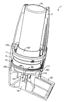
Figure 1 shows a dispensing apparatus, indicated
generally at 1, having a upper body 3, a lower body 5 and a
detachable mouthpiece 20 shown in Figure 8. A dust cap may
be used to cover the mouthpiece 20 when the apparatus is not
in use. As shown in Figure 2, the dispensing apparatus is
also provided with first and second number rings 11,13, a
cog 12 and a sleeve 100. In use the apparatus receives a
pressurised dispensing container 10.
The lower body 5 is open at its upper end. The lower
body 5 houses the cog 12 and the first and second number
rings 11, 13. As shown in more detail in Figure 3, the
number rings 11, 13 rest upon. internal projections 111 of
the main body 5. Such internal projections 11.1 provide
up-facing surfaces upon which the second number ring 13 may
rest and rotate, during use. The first number ring 11 rests
CA 02588686 2007-05-15
- 11 -
and rotates, during use, on top of the second number ring
13. The cog 12 is rotatably mounted within the main body 5
on a cylindrical portion 112 and interacts with both first
and second number rings 11, 13. As can be seen, the axis of
rotation of the cog 12 is offset from the axes of the
numbered rings 11, 13 but parallel thereto so that the cog
12 can interact with both number rings 11, 13 which are
housed in the substantially cylindrical part of the lower
body 5 without impeding axial movement of the container 10.
The lower body 5 is provided at a lower end thereof
with an axial protrusion 121 integral with the lower body 5.
The axial protrusion 121 comprises a hollow elongate portion
into which the valve stem 22 of the container 10 can be
received as a relatively tight interference fit. The hollow
portion is provided with a narrowed constriction against
which the valve stem 22 can abut when the dispensing
apparatus is actuated. The hollow portion forms a conduit
124 that is in fluid communication with the outlet of the
valve stem of the pressurised dispensing container when the
container is inserted into the apparatus. The axial
protrusion 121 protrudes from the lower end of the lower
body 5 as shown in Figure 2. The axial protrusion 121
provides protection for the valve stem when the mouthpiece
20 has been removed and also directs dispensed product into
the removable mouthpiece 20. In particular with the
mouthpiece 20 removed the valve stem 22 is not easily
accessed as it is recessed relative to the distal end of the
protrusion 121. This significantly reduces the chance that
the container 10 could be actuated by direct pressure being
applied to the end of the valve stem 22 which might
circumvent the dose counter mechanism.
CA 02588686 2007-05-15
- 12 -
The lower body 5 and upper body 3 are connectable
together using co-operating formations which are push-fit
together as shown in Figure 2.
The detachable mouthpiece 20 is attached to the main
body 5 by means of a bayonet fitting. As shown in Figures 2
and 8 the mouthpiece 20 is provided with an upstanding rim
120 in which are formed two opposed recesses 123 of roughly
an L-shape configuration. The main body 5 comprises a
circumferential recess 195 which receives the rim 120 when
the two pieces are coupled together. At opposed points of
the circumferential recess 195 the lower body 5 is provided
with retaining lugs 125 which pass along the recesses 123 of
the mouthpiece. Thus the mouthpiece may be coupled to the
lower body 5 by locating the lugs 125 relative to the upper
end of the recesses and then twisting the lower body 5
relative to the mouthpiece 20 whilst applying a compressive
axial force to the two components. This results in the lugs
125 riding along the recesses resulting in the two
components being firmly connected. Accordingly, it is very
simple to change the mouthpiece of the dispensing apparatus,
if desired or remove the mouthpiece for washing. The
mouthpiece 20 is also provided with a spray block 14 for
receipt of the axial protrusion 121. The spray block 14
comprises a conduit having an upper end which receives the
axial protrusion 121 and a lower end which comprises a spray
outlet directed towards the outlet of the mouthpiece 20. The
spray outlet may be provided with a suitably dimensioned
orifice or spray pattern block as known in the art to
produce an atomised spray of product on dispensation.
The first number ring 11 is provided with an upper row
of angled abutment surfaces 41a located on a larger diameter
portion of that number ring as shown in Figure 7. A lower
CA 02588686 2007-05-15
- 13 -
set of angled abutment surfaces are formed on a smaller
diameter portion of the ring in the form of a series of
inwardly directed projections 310 having a triangular cross-
section when viewed from above. The projections 310 are
arranged around the circumference of the lower portion of
the ring 11 so as to form a series of interspersed peaks and
troughs. Each projection 310 comprises two faces 311, 312
on either side of the peak. Preferably, the faces 311, 312
are arranged symmetrically about the peak. The faces 311
and 312 form angled abutment surfaces which engage the
outward projection 304 of the tension arm 300 in use as will
be described below.
The first number ring 11 comprises at least one notch
40 positioned on the outer edge thereof. The first number
ring 11 is also provided with a set of numbering (not shown
in the drawings) from 0 to 9 for each notch 40, so that
after the ninth actuation of the apparatus 1, the notch 40
is in position to interact with the cog 12. In a preferred
embodiment, the number ring 11 will have three notches 40
and, so, will have three sets of numbering from 0 to 9.
The second number ring 13 is provided with an extended
portion 150, as shown in Figure 4, which is positioned to
enable covering of the markings on the first number ring 11
when a container locatable in the housing is empty.
Advantageously, the extended portion 150 provides a clear
indication to a user that the disperising apparatus has
provided its full-quota of dispensations.
The cog 12, as shown in Figure 5 in particular, is
provided with one or more teeth separated by a non-toothed,
cylindrical, spacer 160. A first end 161 of the cog 12
includes four teeth 162 of reduced height and four teeth 164
of full height which in use interact with the first annular
CA 02588686 2007-05-15
- 14 -
member 11. The full height teeth 164 extend from the spacer
160 to the distal face of the first end 161 of the cog 12.
The teeth 50 at a second end of the cog 12 are all full
height and these teeth in use interact with the second
annular member 13. The four teeth 162 having reduced height
are, typically, half the height of the full height teeth
164. Most preferably, the reduced height teeth 162 and full
height teeth 164 are arranged alternately around the
circumference of the cog 12. The cog 12 is provided with
upper and lower axial projections 190 which allow the cog 12
to be rotationally mounted in recesses formed in the lower
body 5 as shown in Figure 3.
As shown ir. Figures 2 and 6, the sleeve 100 comprises
an open-ended cylinder 170 having an upper end 1.71 which can
receive the container 10 to be located in the dispensing
apparatus 1 and a lower end 172 which has a reduced diameter
opening 173 through which the valve stem 22 of the container
10, located within the sleeve 100 may protrude from but
through which the body of the container 10 cannot pass. The
sleeve 100 is provided with two sets of formations on its
exterior surface. The sets of formations are arranged
diametrically opposite one another (only one set of
formations is shown in Figure 6). Each set of formations
comprises first, second and third formations. The first
formation is provided at the lower end 172 in the form of
notches 114. The second formation is provided above the
notches 114 in the form of a tension arm 300. The tension
arm 300 comprises a cantilevered portion 301 which is fixed
to the sleeve 100 at a hinge point 302. Preferably, the
tension arm 300 is provided in a single moulding as part of
the sleeve 100 in which case the hinge point 302 rriarks the
jun.ction between the body of the sleeve 100 and the start of
CA 02588686 2007-09-28
- 15 -
the cantilevered portion 301 of the tension arm 300. A
distal end 303 of the tension arm 300 is provided with an
outwardly directed projection 304. It can be seen from
Figure 6 that the cantilevered tension arm 300 is able to
accommodate flexure in a direction perpendicular to flexure
of the cantilevered projection 178. That is, the outwardly
directed projections 304 of the tensiori arm 300 can flex
substantially radially inwards when pressure is applied to
the projections in a radially inward direction. It will be
appreciated that the shape of the container 10 must
accommodate inward flexure of the tension arms 300. It is
therefore preferable that the position of the tension arms
300 be located to coincide with the neck of the container 10
where it narrows to meet the ferrule of the metering valve,
thereby forming an undercut. Alternatively, the walls of
the container 10 may have formed in them depressions to
accommodate inward flexure of the tensions arms 300. The
third formation is provided at the upper end 171 in the form
of a cantilevered projection 178.
The lower body 5 is provided with a clear portion 30,
or one or more apertures 30 through which portions provided
with markings of the number rings 1.1, 13 are visible. The
CA 02588686 2007-09-28
- 16 -
upper body 3 is transparent to allow a user to easily see
the type of container 10 located in the apparatus 1.
The opening in the upper body 3 is sized such that the
sleeve 100 cannot pass therethrough but so that the
conta.irler 10 is able-to pass through.
In use, the internal components of the apparatus, such
as the cog 12,the sleeve 100 and the number rings 11, 13 can
be loaded into position within the apparatus 1 by separating
the upper body 3 from the lower body 5. The cog, number
rings and sleeve 100 can be insertedinto the opening of the
lower body 5. 'I'he internal projections 110 of the lower body
5 are received slidingly in the notches 114 of the sleeve
100 with the effect that the sleeve 100 is fixed
rotationally relative to the lower body 5. The sleeve 100 is
arranged to pass through the central holes/apertures of the
number rings 11, 13. The upper body 3 is then attached to
the lower body 5. The connection between the upper body 3
and lower body 5 may be designed to prevent easy further
detachment of the two parts to thereby provide a tamper-
resistant means of enclosing the container,10.
The pressurised dispensing container 10 can now be
passed through the hole in the ilpper_ body 3 to be received
in the sleeve 100. The valve stem 22 of the pressurised
dispensirig container. 10 is received in the opening of the
conduit 124 of the axial protrusion 121 as a relatively
tight interference push-fit. When loaded, the number rings
11,13 are located around the container 10 as shown in Figure
3.
In the inserted position the upper end of the container
10 protrudes upwardly through the hole in the upper bod_y 3
as shown in Figure 1. Preferably, the container 10 only
protrudes slightly above the level of the upper body 3. In
CA 02588686 2007-05-15
- 17 -
the illustrated embodiment scallops 17 are provided in the
upper edge of the upper body 3 and the container 10
protrudes above the level of the scallops but does not
protrude above the highest part of the upper edge. The depth
of the scallops 17 allows a user to depress the container 10
sufficiently to actuate the container's valve but reduces
the area of the container 10 that can be gripped by the
fingers of anyone attempting to remove the container 10 from
the apparatus 1. Thus the amount of pulling force that can
be applied to the container 10 is not enough to overcome the
friction produced by the interference fit between the valve
stem 22 and the conduit 124. Also, the fact that the
container 10 does not protrude above the highest part of the
upper edge helps to prevent accidental actuation of the
apparatus when carried in the pocket. Advantageously, this
mechanism of retaining the container 10 within the body
portion can be used on its own without the need to provide
an additional non-return feature.
The apparatus 1 is actuated by depression of the
container 10 which protrudes above the scallops 17 of the
upper body 3. Depression of the container 10 causes the
container 1C and sleeve 100 to move axially within the main
body 5 to actuate the container 10. Actuation causes an
amount of product to be dispensed from the container 10 by
an opposite reaction force from the constriction in the
axial protrusion 121 acting on the valve stem 22, which is
inwardly retracted relative to the remainder of the metering
valve such that an amount of product is dispensed from the
valve stem 22 through the conduit 124 and the valve stem
receiving block 14, from where it is dispensed as an aerosol
through the mouthpiece 20 and inhal.ed by a user inhaling on
the mouthpiece 20. Release of the container 10 causes the
CA 02588686 2007-09-28
- 18 -
container to return to its starting position, owing to the
internal spring bias of the metering valve, ready for
subsequent dispensing.
Each actuatiori of the apparatus 1 causes the first
number ring 11 to rotate a partial increment during the
downstroke of the dispensing container owing to engagement
of the angled abutment surface 179 of the cantilevered
projection 178 with the angled abutment surfaces 41a the
first nuniber ring 11. This partial rotatiori of the first
number ring 11 causes each outwardly directed projection 304
of each tension arm 300 to ride up an angled face 311 of
respective projections 310. This movement is accommodated
by the tension arms 300 as they flex radially inwards. The
relative location of the angled abutment surfaces 41a and
the projections 310 is such that when the down stroke of the
sleeve 100 is completed the outwardly directed projections
304 of the tension arms 300 have ridden up the analed
abutment surfaces 311 and over the peak of the projections
310 such that the outwardly directed projections 304 lie in
contact with the angled abutment surfaces 312 of the
projections 310. Thus, when the container or cap is
released, and the sleeve 100 consequently moves back oii its
up stroke, the completion of the incremental rotation of the
first number ring 11 is achieved by the biasing force of the
outwardly directed projections 304 of the terision arms 300
on the angled abutment surfaces 312 as the tension arms 300
try to return to their unstressed position. This biasing
force completes the rotation of the first number ring 11
such that the outwardly directed projections 304 of the
tension arms 300 lie in the neighbouring trough between the
projections 310 after one actuation. Consequently, the
cantilevered projection 178 and the tension arm 300 (or the
CA 02588686 2007-05-15
- 19 -
pairs of these features where present) act as first and
second indexing members which together act to index the
counter mechanism.
Importantly, the force needed to rotate the first
number ring 11 during a normal mode of operation is less
than the force needed to flex the cantilevered projection
178 about the hinge point 181 sufficiently to allow the
projection to bypass the teeth of the first number ring 11.
Thus, normally the number ring 11 rotates rather than the
cantilevered projection 178 being flexed.
Every ten actuations of the apparatus 1 cause the notch
40 to pass the cog 12, the effect of this being that one of
the full height teeth 164 of the upper row of teeth is
caught in the notch 40 as it rotates, this rotation causes a
corresponding rotation of the cog 12 in the opposite sense.
As a consequence, the second number ring 13 is caused to
rotate iri the same sense as the first number ring 11 by
interaction of the teeth 50 on the bottom of the cog 12 and
the teeth of the second number ring 13. Therefore, it can
be seen that every actuation of the apparatus causes the
value of the numbering visible through the one or more
apertures 30 to be decreased or augmented by a value of one.
If the number rings 11, 13 or cog 12 become jammed or
otherwise inoperative the dispensing apparatus can still be
actuated as follows. On engagement of the angled abutment
surface 179 of the cantilevered projection 178 against the
angled surfaces 41a of the first number ring (which are now
immobile) the elongated portion 180 of the cantilevered
projection flexes about the hinge point 181 so that the
distal end of the elongate portiori 180 moves out of
alignment with the angled surfaces 41a of the teeth of the
first number ring. The cantilevered projection and hence the
CA 02588686 2007-05-15
- 20 -
sleeve 100 as a whole can now move axially downwardly into
the actuated position with the elongated portion 180 of the
cantilevered projection passing between a pair of the teeth
41 of the first number ring 11.
Another advantage of the use of the cantilevered
projection 178 for incrementing the indexing mechanism is
that it provides the dispensing apparatus with a mechanism
for resisting sudden impacts. With some conventional
mechanical dosage counters a problem can occur where the
dispensing apparatus is dropped or otherwise suffers a
sudden impact. This can cause damage to the indexing
mechanism, in particular to the relatively small and
delicate teeth of the counter rings 11, 13 or cause the
indexing mechanism 'to increment or decrement because the
indexing member is held, in the unactuated position, in
close proximity or in contact with the indexing mechanism.
In the present invention the use of the cantilevered
projection 178 provides a degree of inherent flexibility in
the indexing member which allows the indexing member to
absorb sudden impulses of force such as occur when the
device is dropped without leading to damage of the mechanism
or causing the annular members 11, 13 being incremented or
decremented. For example if the dispensing apparatus is
dropped so as to impact on a hard surface with the
mouthpiece lowermost, the force impulse is transmitted
upwardly through the lower body 5 into the annular members
11, 13. The force impulse is then transmitted from the
annular members to the cantilevered projection 178.
However, at this point the cantilevered projection 178 is
able to flex upwardly sufficiently to absorb the imptilse
without the effect that the upper annular member is rotated
relative to the cantilevered projection or damaged. Thus,
CA 02588686 2007-05-15
- 21 -
the inherent flexibility of the cantilevered projection 178
and the fact that a void space 182 is provided around it to
accommodate movement of the cantilevered projection 178,
provides the dispensing apparatus with a mechanism for
coping with impact forces without indexing the indexing
mechanism or causing damage to the mechanism.
Whilst in the specific example details of the invention
are discussed, it will of course be understood that minor
variations in features are still considered to be covered by
the same inventive concept.
In an alternative embodiment, the dispensing apparatus
may comprise, say, three or more number rings: a first
number ring for 'units', a second for 'tens' and a third for
'hundreds'. Further cogs may be provided. Subsequent
number rings for 'thousands' and so on may also be added.
The second and subsequent number rings are rotated by an
arrangement as described herein (by a cog rotated by a
previous number ring), whereby ten incremental rotations of
the previous number ring - as started originally on the
'units' number ring by actuation of the apparatus - causes
an incremental rotation of the subsequent number ring.
Figure 13 illustrates a inodified arrangement wherein
the sleeve 100 i_s additionally provided with one or more
flexible legs 220 that depend from an inner face of the
sleeve 100 and are directed downwardly at an angle towards a
basal inner face of the sleeve 100 in which the lower
opening is formed. The legs 220 are relatively flexible such
that the container 1.0 can be fully inserted by flexing of
the legs. The legs 220 serve two functions. Firstly they
provide a 'snap-fit' arrangement to help ensure a positive
loading action where full engagement of the container 10
with the sleeve 100 is made more consistent. This is
CA 02588686 2007-09-28
- 22 -
achieved because the force required to flex the legs 220 out
of the path of the container 10 ensures that the container
must be inserted into the sleeve with a minimum force.
Once the container 10 has deflected the legs 220 out of its
5 path the force applied to the container 10 acts to shoot
home the contai:ner into abutment with the lower face of the
sleeve. Secondly, the length and angle of the legs 220 act
as a biasing mechanism to prevent slippage between the
sleeve 100 and the container 10 when assembled whatever the
10 orientation of the apparatus. As shown in Figure 13, with
the container fully engaged with its end face abutting the
lower end face of the sleeve 100 the legs 220 are still
flexed and in contact with the sloped undercut of the
container 10 formed by crimping of the ferrule. 'I'hus, the
legs 220 bias the container 10 against the lower face of the
sleeve 100.
If desired the apparatus may be provided with a non-
return feature in place of, or in addition to the
interference fit betweeri the valve stem 22 and conduit 1.24
as a means of retaining the container 10 within the housing.
For example, the internal face of the sleeve 100 may be
provided with a non-return feature 200, shown schematically
;_n Figure 9. The non-return feature 200 may be in the form
of a flexible flange but is shown, and is preferably in the
form of a pair of flexible legs 200 which protrude inwardly
and in a downwards direction. As the container 10 is
inserted into the sleeve1.00 the legs 200 are deflected
outwardly to allow a ferrule 201 of the container 10 to
pass. Once in the assembled position the legs 200 spring
back outwardly to engage in an undercut f_ormation formed
between the ferrule 201 and the body of the container 10 as
shown in, Figure 9. Most preferablv, the distal ends of the
CA 02588686 2007-05-15
- 23 -
legs 200 engage at the internal point of inflection of the
ferrule formed by the crimping of the ferrule as shown in
Figure 9. In this way removal of the container 10 from the
sleeve 100 is prevented or made more difficult since the
legs 200 will act as a strut when a pulling force is applied
to the container 10. It is to be noted that the tightness of
the grip between the legs 200 and the container 10 can be
varied by varying the length and stiffness of the legs 200.
The use of the legs 200 can be in combination with the use
of the flexible legs 220 as shown in Figure 13. Where such a
combination is used the legs 200 and flexible legs 220
perform their separate functions as described above of,
respectively, preventing or resisting removal of the
container 10 from the sl.eeve 100 and biasing the container's
end face against the basal face of the sleeve 100.
Typically, the legs 200 will be less flexible than the
flexible legs 220.
In an alternative arrangement shown in Figure 10 the
sleeve 100 (or an equivalent component) comprises a number
of flexible fingers 210 which are connected to a body of the
sleeve 100 at a lower end but free at an upper end 211. A
number of the fingers 210, preferably alternate fingers, are
provided with inward facing projections 213 which act as the
non-return feature which engage the undercut formed between
the ferrule 201 and body of the container 10. In use, the
fingers 210 are able to flex sufficiently to allow the
container 10 to be inserted into the sleeve 100. However,
the lack of purchase on the container 10 caused by only a
small part of the container protruding above the lower edge
of the scallops results i.n it being relatively difficult to
apply enough force to remove the container from the sleeve
100.
CA 02588686 2007-05-15
- 24 -
A further alternative is shown in Figure 11 which is
similar to the version in Figure 10 except that the fingers
210 are joined together at their upper ends 211. It is also
seen that the projection 213 takes the preferred form of
having a ramped surface configuration which acts to ease
insertion of the container 10 into the sleeve 100 but
resists to a degree removal of the container 10. In use, the
fingers 210 flex outwards in the middle to allow insertion
of the container 10.
Figure 12 shows a further alternative wherein the
fingers 210 are joined to the body of the sleeve 100 at
their upper ends but are free to flex at their lower ends.
Functionally the three arrangements work similarly.