Note: Descriptions are shown in the official language in which they were submitted.
CA 02588718 2007-05-23
WO 2006/058086 PCT/US2005/042478
SYSTEM AND METHOD FOR INTEGRATING POINT OF SALE AND
ELECTRONIC ARTICLE SURVEILLANCE DATA
Cross Reference to Related Application
[0001] The present application claims a benefit of priority to U.S.
Provisional
Application Serial No. 60/630,939 filed on November 24, 2004 entitled
"Integration of Point
of Sale (POS) Data and Electronic Article Surveillance (EAS) Deactivation Data
by Utilizing
an Alarm Management Unit to Provide Correlated Data Reporting" by William Karl
Burkholder et al., the entire contents of which being incorporated by
reference herein.
Background
1. Field of the Invention
[0002] This invention relates to point of sale (hereinafter "POS") and an
electronic article
surveillance (hereinafter "EAS") systems and more specifically to a system and
method for
integrating data from POS and EAS systems by utilizing an alarm management
unit.
2. Description of the Relevant Art
[0003] Current retail establishments utilize a plurality of electronic
equipment within
their outlets. Most important of these include a point of sale system and an
electronic article
surveillance system. POS systems perforin retail transactions and include POS
stations, such
as cash registers, scanners, etc., and other equipment interconnected in a POS
network. The
POS stations, inter alia, identify merchandise, change inventory figures,
(e.g., merchandise's
price, quantity, sale reductions, etc.), and receive payment.
[0004] EAS systems are detection systems that are configured to identify one
or more of
an EAS tags within a given detection region. EAS systems have many uses, but
most often
they are used as security systems for preventing shoplifting in stores. EAS
systems are
readily configurable for a variety of different purposes and typically are
configured to make
use of a number of different technologies.
[0005] A typical EAS system includes an electronic detection unit, EAS tags,
and a
deactivator. Deactivation is commonly known to either deactivate tags attached
or embedded
CA 02588718 2007-05-23
WO 2006/058086 PCT/US2005/042478
in merchandise or detach tags from merchandise. The detection units form an
EAS tag
detection region and are usually placed in high traffic areas, such as
entrances and exits of
stores. The EAS tags have special characteristics and are specifically
designed to be affixed
to or embedded in merchandise or other objects sought to be protected. When an
active EAS
tag passes through the EAS tag detection region, the EAS system sounds an
alarm, e.g., audio
and/or visual alarm, to indicate the removal of the EAS tag from the
proscribed area.
[0006] Therefore, in order for a customer to leave with the purchased
merchandise, the
EAS tag attached thereto must be deactivated either by magnetically
deactivating the tag or
detaching the tag from the merchandise. Typically, EAS deactivators disable
EAS tags
1 o mechanically or electronically and deactivation is accomplished during the
retail transaction
at the POS station. The EAS deactivator is connected to the POS station, which
signals the
EAS deactivator to disable the EAS tag once the merchandise has been paid for,
allowing the
merchandise to be removed from the store. Hence, during a retail transaction,
both the POS
transaction and the EAS deactivation in effect occur at the POS station. As a
result, the POS
station is involved in bidirectional communications with one or more EAS
deactivators. In
one direction, from POS station to the EAS deactivator, the POS station sends
deactivation
commands which are then forwarded to the EAS system to disable the EAS tag. In
the
opposite direction, from the EAS deactivator to the POS station, the EAS
deactivator sends
data concerning which and/or how many EAS tags have just been deactivated.
Subsequently,
the POS station network must also process and transport, both, the EAS
deactivation data and
the POS transaction data.
[0007] This conventional arrangement drains extensive processing resources
from the
POS systems. In addition, this arrangement complicates the installation and
modification of
POS systems (e.g., networking equipment). Furthermore, the EAS deactivation
data is
processed separately from the POS transaction data, without correlating the
two sources of
information. Therefore, there is a need for a system which would alleviate the
burden
typically placed on the POS stations and networks which are routinely required
to process the
bidirectional POS and EAS data. Ideally, such a system would be configured to
remove or
modify bidirectional communication between the POS stations the EAS
deactivators. The
system would also correlate the two types of data to provide important
statistical analysis for
management concerns.
[0008] In one particular useful embodiment, the present invention relates to a
system for
integrating information concerning point of sale (POS) transactions and
electronic article
surveillance (EAS) deactivations. The system includes a POS station configured
to collect
2
CA 02588718 2007-05-23
WO 2006/058086 PCT/US2005/042478
and transmit purchase data concerning purchased merchandise and a deactivation
signal to
disable EAS tag attached to the merchandise. The system also includes an EAS
deactivator
configured to receive the merchandise data and a deactivation signal from the
POS station.
The EAS deactivator is also configured to deactivate the EAS tag, collect data
pertaining to
deactivation of the EAS tag, and transmit the data pertaining to merchandise
and
deactivation. Also included, is an alarm management unit configured to
receive, process and
relay the purchase and deactivation data to a data processing unit, which
analyzes the data
and generates a report based on the data.
Summary
[0009] The present invention relates to a system and method for integrating
POS
transactions and EAS deactivation data and includes a POS station, an EAS
deactivator, an
alarm management unit, and a data processing unit. The POS station processes
POS
transactions, records POS data, as well as signals the EAS deactivator to
disable EAS tags
and transmits recorded POS data thereto. The EAS deactivator disables the EAS
tags and
transmits EAS deactivation data and the POS data to the alarm management unit,
which
relays the information to the data processing unit for data integration and
correlation.
[0010] One embodiment according to the present disclosure relates to a system
for
integrating information concerning point of sale (POS) transactions and
electronic article
surveillance deactivations. The system includes a POS station which collects
first data
pertaining to purchased merchandise with at least one EAS tag and transmits
the first data to
an EAS deactivator. The EAS deactivator receives the first data along with a
deactivation
signal from the POS station and deactivates the EAS tag(s). The EAS
deactivator being
configured to collect second data pertaining to the deactivation of the EAS
tag(s) and to
transmit the first and second data to an alarm management unit. The alarm
management unit
processes and relays the first and second data to a data processing unit which
is configured to
analyze the data and to report the first and second data or generate third
data based on the
first and second data.
[0011] According to a further aspect of the present disclosure, a set of
computer-
executable instructions for collecting information pertaining to a defeated
electronic article
surveillance (EAS) tag, the computer-executable instructions is disclosed. The
set of
computer-executable instructions include the steps of collecting first data
pertaining to
purchased merchandise having at least one EAS tag in a POS station and
transmitting the first
3
CA 02588718 2007-05-23
WO 2006/058086 PCT/US2005/042478
data and a deactivation signal to an EAS deactivator, receiving the
deactivation signal at the
EAS deactivator, the EAS deactivator adapted to deactivate at least one EAS
tag, to collect
second data pertaining to deactivating at least one EAS tag, transmitting the
first and second
data to an alarm management unit, the alarm management unit adapted for
collecting and
storing the first and second data, and processing the first and second data to
generate a third
data based on the first and second data.
[0012] The present disclosure also relates to a method for integrating
information
concerning point of sale (POS) transactions and electronic article
surveillance deactivations is
disclosed. The method includes the initial steps of providing a POS station
for collecting first
1o data pertaining to purchased merchandise having at least one EAS tag and
transmitting the
first data and a deactivation signal to an EAS deactivator. Another step
includes receiving
the deactivation signal at the EAS deactivator, which is adapted to deactivate
at least one
EAS tag and to collect second data pertaining to deactivating at least one EAS
tag. Other
steps include transmitting the first and second data to an alarm management
unit which is
adapted to collect and store the first and second data and process the first
and second data to
generate third data based on the first and second data.
[0013] In another particular useful embodiment, a set of computer-executable
instructions
for integrating information concerning point of sale (POS) transactions and
electronic article
surveillance (EAS) deactivations is disclosed. First, data pertaining to
purchased
merchandise having an EAS tag is collected by a POS station and transmitted
along with a
deactivation signal to an EAS deactivator. Thereafter, the data and the
deactivation signal is
received by the EAS deactivator, which is configured to deactivate the EAS
tag. In addition,
the EAS deactivator is configured to collect data pertaining to deactivation
of the EAS tag
and transmit the data received from the POS station and the deactivation data
to an alarm
management unit, which collects and relays that data. Lastly, the data is
processed at a data
processing configured to analyze the data and generate a report based on the
data.
[0014] In a further particular useful embodiment, a method for integrating
information
concerning point of sale (POS) transactions and electronic article
surveillance (EAS)
deactivations is disclosed. First, data pertaining to purchased merchandise
having an EAS
tag is collected by a POS station and transmitted along with a deactivation
signal to an EAS
deactivator. Thereafter, the data and the deactivation signal is received by
the EAS
deactivator, which is configured to deactivate the EAS tag. In addition, the
EAS deactivator
is configured to collect data pertaining to deactivation of the EAS tag and
transmit the data
received from the POS station and the deactivation data to an alarm management
unit, which
4
CA 02588718 2007-05-23
WO 2006/058086 PCT/US2005/042478
collects and relays that data. Lastly, the data is processed at a data
processing configured to
analyze the data and generate a report based on the data.
Brief Description of the Drawings
[0015] Various embodiments of a system and method for data logging of EAS tags
are
described herein with reference to the drawings wherein:
[0016] Fig. 1 is a schematic block diagrain of a system for integrating POS
and EAS data;
[0017] Fig. 2 is an exemplary computing system for implementing the present
disclosure;
[0018] Fig. 3 is a schematic block diagram of integrated POS and EAS data
flow; and
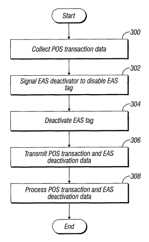
[0019] Fig. 4 is a flow diagram showing a method for integrating POS and EAS
data.
1o Detailed Description
[0020] Preferred embodiments of the present disclosure will be described
hereinbelow
with reference to the accompanying drawings. In the following description,
well-known
functions or constructions are not described in detail to avoid obscuring the
present disclosure
in unnecessary detail.
[0021] A system and method for integrating POS transaction and EAS
deactivation data
is disclosed. In general, the herein disclosed system and method relate to POS
station which
processes merchandise and collects and stores related POS data. The data may
include
information relating to particular merchandise or whether the tag is present
or absent from the
merchandise. The POS station, in turn, transmits the POS data and deactivation
signals to an
EAS deactivator which disables EAS tags and relays POS data as well as EAS
deactivation
data to an alarin management unit. The alarm management unit thereafter
transmits the data
to a data processing unit for data integration and correlation.
[0022] More particularly and with specific reference to the figures, Fig. 1
shows a data
integration system 1 for collecting EAS deactivation and POS transaction data.
System 1 is
typically deployed in a retail environment, e.g., a department store 2. Those
skilled in the art
will understand that the system 1 may be deployed in a plurality of settings
where EAS
systems and POS systems are usually installed. The store 2 may include a
plurality of
departments, e.g., men's apparel, women's apparel, electronics, etc. In
addition, those
departments may be subdivided into predetermined areas, e.g., shoes, fitting
rooms, active
wear, isles, etc. EAS tags are typically affixed to or embedded in the store's
merchandise
and/or the merchandise's packaging in order to prevent shoplifting. Those
skilled in the art
,5
CA 02588718 2007-05-23
WO 2006/058086 PCT/US2005/042478
will appreciate that the EAS tags may be any EAS anti-theft device, such as a
label or other
more sophisticated devices having an outer casing and a plurality of metallic
strips.
[0023] EAS systems typically operate using a transmitter and a receiver
wherein the
transmitter is placed on one side of the detection region and the receiver is
placed on the
opposite side of the detection region. In the case of a retail store, this
detection region is
usually defined at a checkout aisle or an exit. When an EAS tag enters the
detection region,
the EAS tag has a characteristic response to an exciter signal which is
readily detectable. For
example, the EAS tag may respond to the signal sent by the transmitter by
using a simple
semiconductor junction, a tuned circuit composed of an inductor and capacitor,
soft magnetic
strips or wires, or vibrating resonators. This characteristic response is
subsequently detected
by the receiver.
[0024] The system 1 also includes a detection unit 4, a point-of-sale ("POS")
station 6, an
EAS deactivator 10, an alarm management unit 14, and an alarm 12. The
detection unit 4
includes a transmitter and a receiver which defines a predetermined EAS tag
detection region.
The detection region is preferably located around or in proximity to an exit 8
since placing
the detection unit 4 in a high-traffic area increases the chances of detecting
shoplifted
merchandise. The transmitter is configured to produces a predetermined exciter
signal in the
detection region. As a result, an active EAS tag (e.g., a non-deactivated or
non-defeated
EAS tag) passing through the detection region responds to the exciter signal
which is
recognized by the detection unit 4. In that event, the detection unit 4 sends
a signal to the
alarm 12 which generates an alarm, e.g., audio and/or visual alarm.
[0025] POS station 6 may be any device adapted for performing POS
transactions, e.g., a
cash register and may include a display, a keypad, a printer for printing
receipts, and/or a
scanner for reading UPC codes. POS station 6 is typically connected to the EAS
deactivator
10 in order to disable or defeat EAS tags attached to the merchandise.
[0026] More particularly, merchandise can only be removed from the store 2 if
the EAS
tags, which are usually attached to the merchandise or the packaging, are
deactivated or
defeated. The EAS deactivator 10 is typically located near or at the POS
station 6 so that
EAS tag deactivation occurs concurrently with the merchandise sale
transaction. During the
retail transaction, POS station 6 is configured to check out the merchandise,
receive payment,
and signal the EAS deactivator 10 to deactivate the EAS tag. Deactivation may
be
accomplished using any number of methods, such as physical removal of the EAS
tag from
the merchandise (e.g., an EAS tag attached to apparel) or electronic
deactivation of the EAS
tag, so that the EAS tag remains on the merchandise but will not respond to
the exciter signal
6
CA 02588718 2007-05-23
WO 2006/058086 PCT/US2005/042478
(e.g., an EAS tag attached within a DVD case). It is also envisioned that the
EAS deactivator
may operate in a variety of modes. For instance, in a default mode the EAS
deactivator 10
may be constantly on, where any EAS tags brought within the operational range
thereof are
deactivated. In another mode, the EAS deactivator 10 may be turned on to
deactivate EAS
5 tags only when required by the commands from the POS station 6, while
remaining in stand-
by mode for the remainder of the time.
[0027] The EAS deactivator 10 disables the EAS tag upon receiving the signal
from the
POS station 6. In prior art systems, the EAS deactivator 10 transmits
deactivation data (e.g.,
which tags have been deactivated) to the POS station 6. In the present
disclosure, the EAS
10 deactivator 10 transmits the deactivation data to the alarm unit 14, which
is also configured to
receive POS transaction data from POS station 6 via EAS deactivator 10 or
detacher. As can
be appreciated by the present disclosure, this eliminates bidirectional
communications
between the EAS deactivator 10 and the POS station 6.
[0028] The alarm unit 14, in addition to collecting EAS deactivation data and
the POS
transaction data, may be a terminal which controls the EAS system as well as
safety
equipment in the store 2 (e.g., fire alarm, anti-theft alarm, etc.). The alarm
unit 14 may also
be configured as a data terminal or a computing device 300 as shown in Fig. 2.
It is to be
understood that the present disclosure may be implemented in various forms of
hardware,
software, firmware, special purpose processors, or a combination thereof. In
one
embodiment, the present disclosure may be implemented in software or firmware
as an
application program tangibly embodied on the computing device 300.
[0029] The computing device 300 may include one or more central processing
units
(CPU) 390, a random access memory (RAM) 391, a read only memory (ROM) 392 and
input/output (I/O) interface(s) such as a keypad 393, cursor control device
394 (e.g., a mouse,
touchscreen, etc.), a data storage device 398, and display device 395.
Furthermore, the
computing device 300 may also include a networking device 397 which provides
wired or
wireless connectivity to the network 16. In addition, various other peripheral
devices may be
connected to the computing device 300 by various interfaces and bus
structures, such as a
parallel port, serial port or universal serial bus (USB) or wireless. A system
bus 396 may be
included which couples the various components and may be any of several types
of bus
structures including a memory bus or memory controller, a peripheral bus, and
a local bus
using any of a variety of different bus architectures.
[0030] The computing device 300 may also be configured to include an operating
system and
micro instruction code. The various processes and functions described herein
may either be
7
CA 02588718 2007-05-23
WO 2006/058086 PCT/US2005/042478
part of the micro instruction code, firmware, or part of the application
program (or a
combination thereof) which is executed via the operating system. In addition,
the computing
device 300 may be designed to include software for displaying user input
screens and
recording user responses as discussed in more detail below.
[0031] It is to be further understood that because some of the constituent
system
components and method steps depicted in the accompanying figures may be
implemented in
software, the actual connections between the system components (or the process
steps) may
differ depending upon the manner in which the present disclosure is
programmed. Given the
teachings of the present disclosure provided herein, one of ordinary skill in
the related art will
to be able to contemplate these and similar implementations or configurations
of the present
disclosure. The data logging method of the present disclosure may be used at
several levels,
including the operating system, the application level, or by the application
components.
[0032] The alarm unit 14 is contemplated to connect to a communications
network 16
which allows the alarm unit 14 to transmit the collected POS transaction and
EAS
deactivation data to a data processing unit 18. Those skilled in the art will
appreciate that
POS station 6, EAS deactivator 10, and alarm unit 14 may be interconnected in
a variety of
ways, using wired and/or wireless interfaces. This allows for the
interconnected devices to
communicate with each other and share data.
[0033] The networlc 16 may be a local area network (LAN), wide area network
(WAN),
the Internet and/or any known network that couples a plurality of computing
devices to
enable various modes of communication via network messages. For example, the
network 16
may be a corporate intranet including a single server and multiple personal
computers housed
within a single facility, or alternatively, multiple servers with multiple
personal computers
located in different geographic locations.
[0034] The data processing unit 18 may be a central server which is part of a
data storage
facility for the store 2. In this instance, the data processing unit 18 would
be configured to
process the POS transaction and EAS deactivation data from alarm unit 14 and
compile the
data in a predetermined format. In addition, the data processing unit 18 may
be configured to
have access to other types of data related to the store 2, (e.g., store
occupancy, POS
transactions, EAS tag deactivations, etc.) typically obtained from the POS
station 6 or other
devices connected to the network 16. The data processing unit 18 may combine
such
information with the data received from the alarm unit 14 to generate reports
concerning
shoplifting trends in the store 2 as discussed in more detail below.
8
CA 02588718 2007-05-23
WO 2006/058086 PCT/US2005/042478
[0035] Fig. 3 shows a schematic block diagram of integrated POS and EAS data
flow
(also discussed in conjunction with Fig. 4) showing one particularly useful
method for
integrating POS and EAS data. More particularly, in step 300, a POS
transaction occurs at
the POS station 6. This transaction typically involves identifying the
merchandise (e.g.,
scanning UPC code via attached scanner, inputting identifying infomiation
manually, etc.) in
order to obtain the merchandise's pricing information, receiving payment
(e.g., cash, credit
card, bank check, etc.), as well as collecting and storing POS transaction
data which includes
payment information, any discounts or surcharges, as well as customer
identity, cashier
identity, etc. The POS transaction data is time stamped (e.g., with date and
time of the
transaction) and transmitted to the EAS deactivator 10 as represented by a
data stream 20.
[0036] In step 302, the POS station 6 signals the EAS deactivator 10 to
disable the EAS
tag attached to the merchandise (if present). The deactivation signals are
shown in a data
stream 22. The data stream 22 includes the identity of the merchandise that
was purchased in
step 300, this allows the EAS deactivator 10 to disable any EAS tags
associated with the
merchandise.
[0037] In step 304, the EAS deactivator 10 deactivates any EAS tags found on
the
merchandise. This may be accomplished by contacting the detector 4 or a
centralized EAS
system computer (not shown) which may include a data base listing the EAS tag
and detector
4 with which the EAS tag is registered. In conventional POS and EAS systems,
POS station
2o 6 and the EAS deactivator 10 are involved in bidirectional communication.
After the
deactivation, the EAS deactivator 10 transmits the deactivation data which
includes the
presence of an EAS tag, the deactivations performed, etc. back to the POS
station 6, which
would then compile the EAS deactivation data with the POS transaction data. As
can be
appreciated, this bidirectional communication tends to slow down and burden
the POS
system.
[0038] In according with the present disclosure, in step 306 the EAS
deactivator 10
transmits the POS transaction data in a data stream 24 and the EAS
deactivation data in a data
stream 26 to the alarm unit 14, thereby eliminating the need for bidirectional
communication.
Those skilled in the art will appreciate that the POS station 6 may transmit
POS transaction
3o data directly to the alarm unit 14, which also eliminates the bidirectional
communications
between the POS station 6 and the EAS deactivator 10.
[0039] In step 306, the alarm unit 14 stores and forwards the POS transaction
and EAS
deactivation data to the data processing unit 18 through the network 16. The
data processing
unit 18 includes a database utilized by a data-mining package, which in step
308, correlates
9
CA 02588718 2007-05-23
WO 2006/058086 PCT/US2005/042478
the number of merchandise items processed at the POS station 6 with the number
of
deactivations processed by the EAS deactivator 10. The correlated data may
include, for
example, the following information, a cashier with an ID code 4321, logged
into register No.
123, started transaction 0001, scanned item 12345678 on 05/10/05 at 10:25:42,
two EAS
deactivations occurred, ended the transaction 0000. Since this information
consists of text
characters, it may all be stored in a string where a delimiting character,
such as a comma is
used denote different data fields (e.g.,
4321,0123,0001,12345678,05102005,102542,002,0000). Those skilled in the art
will
appreciate that other data structures may be used depending on the type of
data collected.
lo [0040] The correlated information may also be used for tag compliance
reports,
effectiveness of cashier personnel in POS transactions. Those skilled in the
art will
appreciate that data processing may be accomplished at the alarm unit 14 and
that the data
processing unit 18 is described in the present disclosure to illustrate the
different stages of the
method.
[0041] In determining tag compliance, the data processing unit 18 would
compare the
number of EAS tags that have POS station 6 attempted to deactivate with the
number of EAS
tags actually disabled by the EAS deactivator 10. If the numbers are not the
same, it denotes
that either an insufficient or extraneous number of disablements occurred. If
there were an
insufficient number of deactivations, the store 2 is indirectly affected,
since the active EAS
tags which were not properly deactivated would trigger an alarm causing
unnecessary
embarrassment and delay to the consumers when they would attempt to leave the
store 2.
This may reflect poorly on the image of the store 2. Conversely, if there were
too many
deactivations, then the EAS tags which were improperly deactivated, would
allow for
merchandise containing them to be removed from the store 2 without triggering
the alarm 12.
Such errors may be the result of human error (e.g., the cashier operating the
POS station 6
improperly deactivates the EAS tag). This results in more direct harm to the
store 2 since that
merchandise can be easily stolen. Correlating EAS deactivation and POS
transaction data
allows the managers of the store 2 to measure performance of sales personnel
and take
appropriate action (e.g., provide more training, transfer, termination, etc.).
[0042] By enabling the EAS deactivator 10 to function as one of or as the only
data
collection source, many additional benefits become readily available to the
owner of the store
2, suppliers, and equipment manufacturers. More specifically, correlation of
deactivation
data with the scanning data provides a variety of valuable analytical tools.
CA 02588718 2007-05-23
WO 2006/058086 PCT/US2005/042478
[0043] The system allows for verification of tag compliance for retailers as
well as
manufacturers. For example, if all of a manufacturer's merchandise is tagged
when it is
supplied to a retail establishment, the system can correlate deactivation with
POS information
to determine the percentage of manufacturer's goods which are mistagged (e.g.,
label
positioned too far from bar code). Moreover, employee misconduct is readily
identifiable
with the presently proposed system. For instance, internal theft by sales
personnel can be
identified by comparing the number of POS scans with the number of EAS
deactivations.
The system or the resulting data gathered therefrom may also be used to
identify items which
are improperly tagged or labeled (e.g., label positioned too far from bar
code).
lo [0044] Integrity of the EAS deactivator(s) or the POS terminals(s) may also
be readily
identified as part of the presently disclosed methods or systems. For example,
if the number
of deactivations is significantly lower or higher than the number of scans,
the cause of the
discrepancy may be attributable to malfunctioning deactivating equipment.
[0045] The invention according to the present disclosure integrates the POS
transaction
and EAS deactivation data which allows for correlation of relevant information
to determine
the effectiveness of the personnel and/or equipment. Furthermore, the
integration eliminates
the need for bidirectional communication between the POS station and the EAS
system
wherein allows for more effective data processing and increased data
throughput.
[0046] While several embodiments of the disclosure have been shown in the
drawings, it
is not intended that the disclosure be limited thereto, as it is intended that
the disclosure be as
broad in scope as the art will allow and that the specification be read
likewise. Therefore, the
above description should not be construed as limiting, but merely as
exemplifications of
preferred embodiments. Those skilled in the art will envision other
modifications within the
scope and spirit of the claims appended hereto.
11