Note: Descriptions are shown in the official language in which they were submitted.
CA 02588960 2007-05-30
WO 2006/060566 PCT/US2005/043458
An Apparatus to Automatically Lyse A Sample
Related Applications
This application claims priority of U.S. provisional application, serial
number
60/633,037, filed December 2, 2004, and entitled "An Autolysing Device", by
the same
inventors. This application incorporates U.S. provisional application, serial
number
60/633,037 in its entirety by reference.
Field of the Invention
The present invention relates to a method of and an apparatus for
automatically lysing
a sample. In particular, the present invention relates to a method of and an
apparatus for
automatically lysing a sample using ultrasonic energy.
Background of the Invention
Current lysing techniques use heat, chemicals, mechanical grinding/bombardment
or
a combination of these to achieve cell/spore/tissue disruption.
Methods that rely on chemical or heat lysis alone often require a number of
manual
steps that the user must strictly follow. If chemicals are used for lysing,
often the lysing
protocol will require that chemical additives be neutralized after lysing to
prevent inhibition
in later analyses. This adds complexity, time, and cost to the process.
Mechanical grinding methods, such as using a mortar and pestle, are also
manual
in nature and thus their effectiveness and repeatability are dependent on the
skill of the
technician. The additional step of cleaning all of the instruments after each
test is required to
eliminate the risk of cross contamination between samples.
Current devices that use ultrasonic energy for mechanical lysing require the
transducer tip be immersed into the liquid sample during sonication, which
again presents the
risk of cross contamination between samples if the transducer tip is not
thoroughly cleaned
between tests. Also, accessibility of the liquid sample to introduce the
transducer tip
necessitates that the liquid sample be contained in an open environment. Such
an open
environment increases the possibility of contamination via splashing or
atomization.
Another method of mechanical disruption is called the "Bead Beater," where the
sample is put into a container together with rigid beads (e.g. glass or
stainless steel spheres).
The container is then violently shaken for a set amount of time in a manner
similar to a paint
mixer. This method is similar in principle to using ultrasonic energy for
mechanical
1
CA 02588960 2007-05-30
WO 2006/060566 PCT/US2005/043458
disruption, but with a lower fr equency and higher amplitude of shaking. Cross
contamination
between tests is not an issue if new containers are used for each sample,
otherwise, the
container must be thoroughly cleaned before each new test. However, for some
samples, a
higher level of agitation is required.
It would be advantageous to develop a lysing system and method that is more
automated, more efficient, and less prone to contamination.
SummarXof the Invention
Embodiments of the present invention are directed to a standalone bench top
laboratory instrument designed to disrupt, or lyse, cells, spores and tissue
samples using
ultrasonic energy. The lysing device is programmable, allowing the user
control over lysing
protocol parameters, such as the sample volume, sonication power level, and
lysing duration.
Such programmable control enables optimizing protocols for specific targets.
Once a lysing
protocol is entered, the device automatically lyses the sample according to
the entered lysing
protocol. The lysing device also provides a cooling feature, enabled by a heat
exchanging
sub-assembly, which prevents the sample from exceeding a maximum set
temperature during
operation. During certain lysing protocols, temperatures can increase to a
point that are
potentially destructive to particular samples. In these cases, the heat
exchanging sub-
assembly can be used to transfer heat away from the sample.
The lysing system of the present invention preferably utilizes a disposable,
individually capped sample vial for each sample to be lysed, minimizing the
risk of cross
contamination between tests. The sample can be combined with mechanical
agitation media
(e.g. glass spheres), chemical lysing reagents (e.g. NaOH), other conventional
lysing
techniques, or nothing depending on the lysing protocol. A sample vial holding
the sample is
inserted into the lysing device such that the bottom of the sample vial comes
in contact with
the transducer tip of the ultrasonic transducer. The transducer tip does not
come in contact
with the sample. The sample vial is inserted into a vial mount within the
lysing device. Heat
blocks are pressed tightly against the side walls of the sample vial. The heat
blocks are each
mounted to a Thermoelectric Cooler (TEC) and heatsink. The ultrasonic
transducer transmits
ultrasonic energy through the bottom of the sample vial and into the sample to
cause
cell/spore/tissue disruption. When the cooling function is activated, the TECs
actively cool
the sample by pulling heat from the sample vial via the heat blocks.
Preferably an auxiliary
fan blows across the TECs and heatsinks to maintain the heat removal rate.
2
CA 02588960 2007-05-30
WO 2006/060566 PCT/US2005/043458
Brief Description of the Drawings
Figure 1 illustrates a perspective view of an automatic lysing device
according to the
preferred embodiment of the present invention.
Figure 2 illustrates a top down view of the control panel of the lysing
device.
Figure 3 illustrates an internal side view of the lysing device.
Figure 4 illustrates an exploded view of the lysing device.
Figure 5 illustrates an exploded view of the lysing engine.
Detailed Description of the Present Invention
Figure 1 illustrates a perspective view of an automatic lysing device 10
according to a
preferred embodiment of the present invention. The lysing device 10 includes a
housing 20,
a main power switch 30, and a control panel 40.
Figure 2 illustrates the control panel 40 in greater detail. The control
pane140 is a
user interface that enables a user to input various lysing protocol
parameters. A visual
display 42 displays the input parameters as well as feedback and status
information during
operation. The display 42 is preferably a liquid crystal display (LCD).
Alternatively, any
conventional display device is used. Less desirably, a printer such as a paper
tape printer,
can be used. A volume button 48, a power button 50, a duration button 52, and
a cooling
button 54 enable the user to enter a volume parameter, a power parameter, a
duration
parameter, and a cooling parameter, respectively. A numeric keypad 46 enables
the user to
enter numeric values associated with the volume, power, duration, and cooling
parameters.
The lysing device 10 (Figure 1) is preferably configured to lyse sample
volumes in the range
of about 1.0 mL to about 3.0 mL Alternatively, the lysing device 10 is
configured to accept
sample volumes less than 1.0 mL and greater than 3.0 mL. The volume parameter
is
preferably entered in 0.1 mL increments. Alternatively, the volume parameter
is entered in
smaller or larger increments as required. In a further alternate embodiment,
the user can also
provide the type of power to which the actual wattage figures refer.
In the preferred embodiment, the power parameter is set according to one of
five
available power settings. The power settings are numbered from "1" to "5" with
"1" being
the lowest power. Alternatively, more or less than five power levels are
configured. Power
level settings are used instead of actual wattage figures, such as "10 watts",
in order to avoid
possible user confusion. For example, when inputting a specific wattage level,
it may be
unclear as to whether the input wattage level refers to power delivered by the
power supply,
power delivered by the ultrasonic transducer, or power absorbed into the
sample. In an
3
CA 02588960 2007-05-30
WO 2006/060566 PCT/US2005/043458
alternative embodiment, the system is configured to accept actual wattage
figures for the
power parameter. In a further alternate embodiment, the user can also provide
the type of
power to which the actual wattage figures refer.
The duration parameter corresponds to the amount of time that ultrasonic
energy is to
be applied to the sample, also referred to as lysing time. Preferably the
lysing time is entered
in minutes and seconds.
In general, the various combinations of possible volume, power, and duration
parameter values collectively result in a performance envelope. The lysing
device 10 is
configured such that the instrument does not allow the user to run a lysing
protocol with
parameters that do not fall within known, or predefined, combination levels.
Such a
constraint prevents potential hazardous parameters combinations from being
executed, for
example running a very small volume at a very high power. In this manner, the
potential for
damaging the equipment and/or the sample is reduced. When parameter values are
input that
do not fall within the predefined performance envelope, an error message is
displayed on the
display 42, and the user is prompted to change one or more of the parameter
values.
Although the lysing device 10 is described as using the volume parameter, the
power
parameter, the duration parameter, and the cooling parameter, it is understood
that more, or
less, parameters can be used.
Once acceptable volume, power and duration parameters are set, a start button
58 is
pressed and lysing begins. The display 42 shows elapsed time counting down to
zero, as well as the set volume and power parameters. Operation is halted at
any time by
pressing a stop button 60.
In some cases, the lysing protocol, and corresponding parameter values, is not
known
and a new protocol needs to be developed. When developing a new protocol, the
exact
lysing duration may not yet be known and the user must instead manually
control the timing.
A pulse button 56 enables the user to manually lyse the sample at the set
volume and power
level. Ultrasonic energy is applied to the sample vial as long as the pulse
button 56 is
depressed, and the display 42 shows the elapsed pulse time by counting up. In
the preferred
embodiment, internal sensors continually monitor the temperature of the
sample. If the pulse
button 56 is held down for too long, overheating may result. Temperature
thresholds are
preferably defined such that if the temperature rises above a given threshold,
application of
the ultrasonic energy is halted.
Memory preset buttons 44 are provided such that commonly used protocols are
stored
and accessed with a single button press. Preferably, five preset buttons 44, A
through E, are
4
CA 02588960 2007-05-30
WO 2006/060566 PCT/US2005/043458
provided. Alternatively, more or less than five preset buttons can be
configured.
The lysing device 10 includes the ability to cool the sample. The cooling
parameter is
preferably used to set a specific temperature to which the sample is cooled.
Alternatively,
the cooling parameter sets a target temperature range. Still alternatively,
the cooling
parameter is set to either on or off, with no specific temperature target set.
Such a cooling
feature is useful with certain protocols where the heat from sonication is
undesirable, such as
damaging RNA or reducing the rate of blood coagulation. The ability to cool
the sample
during sonication or pre-cool the sample prior to sonication also enables the
application of
longer duration lysing without overheating the sample or the sample vial.
The control pane140 also includes an access lid 62. The access lid 62 provides
the
user access to a sample holding area, referred to as a vial mount 110 (Figure
5), where a
sample container, such as the sample vial, is placed for execution of a lysing
protocol.
Figure 3 illustrates an internal side view of the lysing device 10. The lysing
device 10
includes two compartments, a lysing engine compartment and an electronics
compartment.
The lysing engine compartment includes a lysing engine 100. The electronics
compartment
includes control electronics 70, a power supply 80, and an electronics cooling
fan 90. The
control electronics 70 are coupled to the control pane140 (Figure 2) via
connection 72.
Configuring the lysing device 10 into the lysing engine compartment and the
electronics
compartment provides thermal isolation and fluid/electrical isolation. Thermal
isolation
keeps heat generated during sonication within the lysing engine 100 from
heating the control
electronics 70 within the electronics compartment, and keeps heat generated by
the control
electronics 70 and the power supply 80 from heating the lysing engine 100.
Fluid/electrical
isolation keeps fluids, such as the sample, cleaning agents, and TEC
condensation away from
sensitive electrical components within the control electronics 70.
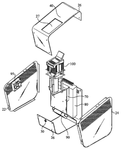
Figure 4 illustrates an exploded view of the lysing device 10. The housing 20
(Figure
1) preferably includes side panels 22 and 24, top cover 26, and bottom panel
26. Each of the
side panels 22 and 24 are preferably perforated for venting. Attached to at
least orie of the
side panels 22 and 24 is an auxiliary TEC fan 95. The auxiliary TEC fan 95
blows air drawn
through the perforated vents of the housing past the lysing engine 100 for
cooling. The top
cover 26 includes the control panel 40 and an opening 27. A top portion of the
lysing engine
100 protrudes through the opening 27 to provide the user access via the access
lid 62.
Although the housing 20 is illustrated in Figure 4 as comprising 4 pieces, the
housing 20 can
alternatively comprise any number of component pieces.
CA 02588960 2007-05-30
WO 2006/060566 PCT/US2005/043458
An exploded view of the lysing engine 100 is illustrated in Figure 5. The
lysing
engine 100 includes a vial nest 180, a vial mount 110, heat blocks 120 and
122,
thermoelectric coolers (TECs) 130, heat sinks 140 and 142, ultrasonic
transducer 150,
compression spring 160, and transducer mount 170. The vial nest 180 includes a
release
latch (not shown) and the access lid 62. The top portion of the vial nest 180,
including the
release latch and the access lid 62, protrudes through the opening 27 (Figure
4) of the top
cover 26 (Figure 4).
The vial mount 110 is configured to hold a sample vial 200. When the access
lid 62
is open, an access opening 182 in the vial nest 180 provides access to the
vial mount 110.
The sample vial 200 is placed into or removed from the vial mount 110 through
the access
opening 182.
A bottom portion of the ultrasonic transducer 150 is coupled to the
compression
spring 160. The transducer mount 170 holds and axially guides the ultrasonic
transducer 150
and the compression spring 160 in place relative to each other. The transducer
mount 170 is
mounted to a bottom surface of the vial mount 110. In this manner, the
ultrasonic transducer
150 is properly positioned relative to the vial mount 110. The vial mount 110
is preferably
configured with an opening (not shown) in the bottom surface such that a
transducer tip 152
of the ultrasonic transducer 150 passes through the opening and contacts a
bottom surface of
the sample via1200 placed within the vial mount 110.
The sample via1200 is placed into the vial mount 110. Subsequent closing of
the
access lid 62 compresses the bottom of the sample vial 200 against the
transducer tip 152. A
predetermined force is maintained by the transducer tip 152 against the bottom
of the sample
vial 20 by the calibrated compression spring 160. Efficient transfer of the
ultrasonic energy
from the ultrasonic transducer 150 to the sample within the sample via1200 is
dependent in
part upon maintaining the contact between the transducer tip 152 and the
bottom of the
sample via1200 according to the predetermined force. Maintaining proper
predetermined
force also plays a role in proper execution of any given lysing protocol, as
the power
parameter is a key variable in such calculations.
Although the compression spring 160 preferably maintains a substantially
constant
force of the transducer tip 150 against the bottom of the sample vial 200, the
coupling that
occurs at this interface changes during lysing due to heating of the interface
and slight
positional changes due to the mechanical movement. To compensate for this
drift and
maintain the set input power level, a feedback loop circuit is preferably
incorporated into the
control electronics 70 that control the ultrasonic transducer 150. The
feedback circuit
6
CA 02588960 2007-05-30
WO 2006/060566 PCT/US2005/043458
preferably samples the voltage and current fed to the ultrasonic transducer
150, and computes
the power delivered to the transducer tip 152 in real time, preferably ever 10
msec. The
control electronics 70 then adjust the supply voltage internal to a voltage
controller of the
ultrasonic transducer 150, which changes the drive voltage to the ultrasonic
transducer 150.
The impedance of the ultrasonic transducer 150 and the voltage drive level
then determines
the current drawn.
When the sample vial 200 is positioned in the vial mount 110, two spring-
loaded heat
blocks 120 and 122 press against the sides of the sample via1200. In this
manner, a first
surface of each of the heat blocks 120 and 122 is in contact with the sample
vial 200 to
provide a thermal contact for heat transfer. A second surface of each of the
heat blocks 120
and 122 is preferably in contact with the Thermoelectric Cooler (TEC) 130.
Although not
shown in Figure 5 due to the angle of perspective, a second TEC is mounted on
a back side
of the heat sink 142 in a manner similar to the first TEC 130. The TEC 130 and
the second
TEC (not shown) are preferably mounted to a back side of the heat sink 140 and
the heat sink
142, respectively. A "hot" side of each TEC is mounted to the heat sinks 140
and 142.
When the cooling function is activated, the TECs are energized causing one
side to get cold
(below the ambient air temperature) and the other side to get hotter then the
ambient. The
cold sides of each TEC, mounted to the heat blocks 120 and 122, extract heat
generated from
the sample during application of the ultrasonic energy sonication. The
auxiliary TEC fan 95
(Figure 4) cools the heat sinks 140 and 142 to maintain a temperature gradient
across the
TECs necessary for proper operation.
A temperature sensor (not shown) is preferably mounted to at least one of the
heat
blocks 120 and 122 to monitor the temperature. This temperature is directly
correlated to the
temperature of the sample vial 200 and the sample within. Maintaining the
temperature
within a predetermined range expands lysing protocol capability. Additionally,
measuring
the temperature, and by extension using the cooling feature of the lysing
device 10, is used
for a variety of safeguard functions. When the lysing device 10 senses
potential overheating,
the sonication process is automatically stopped or reduced. If the cooling
parameter was not
previously turned on, the TECs are activated at this time, rapidly cooling the
sample via1200
and the sample within to a safe temperature.
During normal operation of the lysing device 10, it is expected that the
sample will
experience some heating, which often enhances lysing. Although not high enough
to present
a risk of vial rupture or damage to the target, these temperatures may be high
enough to
startle, or mildly burn, the user if the sample vial 200 is removed from the
instrument and
7
CA 02588960 2007-05-30
WO 2006/060566 PCT/US2005/043458
handled (e.g. risk of dropping the vial and inadvertent spillage). To minimize
such a risk, the
lysing device 10 includes a solenoid safety interlock 184, which disables the
release latch, to
prevent the user from releasing the access lid 62 and accessing the sample
vial 200 before it
has cooled down to a safe temperature. Momentarily activating the TECs after
completion of
the lysing protocol rapidly cools the sample vial 200 and the sample within to
a "safe"
temperature, and shortens the period waiting for the safety interlock 184 to
release the access
lid 62.
Lysing effectiveness has been shown using Bacillus Globigii (BG) bacteria
spores.
3mL samples with 104 cfu/mL concentration of BG combined with 240 mg of glass
beads
(150 - 212 micron diameter) have been sonicated at power level two for 10
minutes and then
amplified using PCR showing successful lysing had occurred. Preferably, power
level two is
equivalent to delivering 8 watts directly to the sample.
The lysing engine 100 is preferably designed as an individual subassembly. As
such,
the lysing engine 100 can alternatively be used, with little or no changes,
for alternative
instrument configurations. Such alternative instrument configurations
including ganging
together lysing engine sub-assemblies in multi-station systems, or combining a
lysing engine
sub-assembly with other devices into a single instrument.
The present invention has been described in terms of specific embodiments
incorporating details to facilitate the understanding of the principles of
construction and
operation of the invention. Such reference herein to specific embodiments and
details thereof
is not intended to limit the scope of the claims appended hereto. It will be
apparent to those
skilled in the art that modifications may be made in the embodiment chosen for
illustration
without departing from the spirit and scope of the invention.
8