Note: Descriptions are shown in the official language in which they were submitted.
CA 02588962 2007-05-18
WO 2006/054178 PCT/IB2005/003676
Thin IOL
Background of the Invention
The present invention relates to iniTaocular lenses (also comrnonly referred
to as
IOLs), and more particularly relates to a thin YOLs that cau be inserted
through a very
small incision in tlie eye and into the evacuated capsular bag of an eye.
Cataract surgery commonly involves removal of the eye's natural but clouded
lens wltich is located i-n the capsular bag using a surgical techmique known
as
phacoemulsircation. It is desirable to have an incision in the eye as small as
possible to
improve heaiing and discourage .formation of post-cataraot astigmatism caused
by the
healed incision. The standard of today's incision size is 3mm or less. With
even more
recent surgical techniques, i.e. bi-manual phacoemulsification or laser-phaco,
incisions
of less than 2mm are possible. Of course if the IOL aztd/or the insertion
instrument are
larger than the incision size, the incision must be enlarged.
Tn order to pass a flexible IOL through a small incision, it must be
compressed to
a smaller size and inserted in the eye using an instrument such as forceps or
an IOL
inserter. Examples of IOL inserters may be seen in coxnmonly assigned U.S.
Patent Nos.
5,944,725 and 6,336,932. It will thus be appreciated that the mate,raal and
dimensions of
the IOL will dictate how small the IOL may be compressed without undergoing
damage
(i.e., larger dimensioned IOLs will not compress as small as a smaller sized
IOL). Of
course, the IOL caimot be so small as to lose its intended purpose of
restoring the
functxon of the eye's natural lens. Proper functioning of the IOL requires the
IOL to
renlain as stable as possible in the eye since movement fhereof can distort
the light rays
CA 02588962 2007-05-18
WO 2006/054178 PCT/IB2005/003676
passing therethrough onto the retina_ Positioning elements known as haptics
are thus
incorporated into the IOL design to help position and stabilize the optic in
the capsular
bag. Many different haptic configurations exist yet there remains a nced for
an IOL of a
relatYVely small size which allows the lens to be compressed and delivered
through a
small incision, preferably on the order of about 2 mm or less, while also
maintaining the
optic very stably in the eye despite compressive forces being applied thereto.
Coznpressive forces may occur, for example, from sluinlcage of the capsular
bag which
occurs in the few months following eataract extraction surgery_
Summary of the Invention
Aspects of the present invention address the above stated need by providing a
thin, foldable, IOL for placement in an evacuated capsular bag of an eye, the
IOL
comprising an optic having opposite anterior and posterior surfaces surrounded
by a
periphery. In an embodiment, four flexible haptics extend radially outwardly
from the
periphery, the haptics each having an elongated section and tenninating in a
free end.
The Crst and second haptics are spaced from one another along a first portion
of the optic
edge and the third and fourth haptics are spaced from one another along a
second portion
of the optic edge wlii.ch is opposite t'he first portion of the optic edge.
In some embodimcnts, the free end of each haptic include at least two spaced
fingers that extend in an anterior direction, The fingers flex and decrease
the radius of
curvature thereof in response to a radial compressive force applied thereto
while the
optic remains substantially aligned along the cye's optical axis. The fingers
may also
move toward one another to absorb the tangential forces imparted by the
shrinking
capsular bag. In some embodinients, the fingers each have a length preferably
about a
2
CA 02588962 2007-05-18
WO 2006/054178 PCT/IB2005/003676
quarter the length of the respective elongated sections. In a further
preferred einbodiment
of the invention, the proximal haptic length is thicker tluzn. a respective
distal haptic
length.
In a preferred embodiment, the IOL fnrther comprises a sharp edge dehiied
along
the optic periphery. When inserted into the evacuated capsular bag of an eye,
the sharp
edge presses against the posterior wall of the bag and acts as a barrier
against cellular
migration and posterior capso.lar opacification caused thereby.
Embodiments of the invention are direct to a foldable TOL, comprising: a) an
optic having a geometric center and a periphery, b) at least two haptics
coupled to said
optic, each having a proximal end and a distal end, eaeh of said haptics
having a
thiclniess that decreases by at least 10% from the proximal end to the distal
end, In
some of the embodiments, each of said haptics has a thickness that decreases
fronx the
proximal end to the distal end by 10% to 60%. In some of the embodiments, each
of said
haptics has a thiclrness that decreases f-rom the proxiinal end to the distal
end by 15% to
40%. In some einbodiments, the decrease in thiclrness in each haptic is
measured over a
centra165% portion of each haptie, Each haptic ntay include at least one step.
In some
embodimexxts, each haptic includes at least two steps. In some embodiments,
the
thickness decreases smootlily over the ]ength of the haptics. In some
embodiments, the
thickness decreases linearly over the length of the haptics. The thi=ckness
may decrease
monotonically over the length of the haptics.
Some embodiments a7re directed to a foldable IOL, eomprising a) an optic
having
a geometric center and a periphery, b) at least two flexible hapties coupled
to the optic,
each haptic liaving an anterior surface and a posterior surface, and a
proximal end and a
distal end, each baptie being concave on the anterior surface between the
proximal end
3
CA 02588962 2007-05-18
WO 2006/054178 PCT/IB2005/003676
and distat end. In some embodiments, at least one of the haptics has a single
curvature
between the proximal end and the distal end. In some embodirr-ents, at least
one of the
haptics has at least two curvatures between the proximal end and the distal
end. In some
embodiments, at least one of the haptics has a curvature that varies
continuously between
the proxirnal end and the distal end. In some embodiments, for at least one of
the
haptics, the curvature of the anterior surface a-nd the posterior surface is
substantially the
same.
Dimensions and measurements as described herein refer to a finished (x.e:,
hydrated) lens. The dimensions are ineasuzed while supporting the IOL using
the
posterior surface of the optic.
Brief Description of the Drawing
Figure 1 is a plan view of an IOL according to an embodiment of the invention
as
implanted in a capsular bag;
Figure 2 is a cross-sectional view i:h.ezeof as talcen generally along the
line 2-2 of
Figure 1;
Figure 3 is a cross-sectional view thereof as taken along the line 3-3 of
Figure 1;
Figure 4 is a perspective view of the IOL of Figure 1 showing the IOL in the
unstressed
state;
Figure 5 is an enlarged, fragmented view of one of the IOL haptic rree ends;
Figure 6 is an enlarged, fka.gmented view of the upper haptic shown in Fig. 2;
Figures 7A and 7B are enlarged, fragmented side views of IOL haptios liaving
steps;
Figure 7C is an enlarged, fragmented side view of IOL haptics having a linear
reduction
in thiclaiess;
4
CA 02588962 2007-05-18
WO 2006/054178 PCT/IB2005/003676
Figures 8A and 8B are enlarged, ;Cragznented side views of IOL haptics having
concave
anterior surfaces; and
Figures 9A and 9B are enlaiged, fragmented top views of IOL haptics ha.ving
fingers,
Detai,led Descr.iption of Preferred Eanbodi.ment
Referring now to the drawings, tliere is scen in the various Figures a
preferred
einbodiment of an IOL (IOL) 10 according to the invention. IOL 10 includes an
optic 11
having opposite anterior and posterior surfaces 12, 14, respectively, defining
a geometric
center GC and a periplieiy 16. The te.rms "anterior" and "posterior refer to
the anterior
and posterior directions when IOL 10 is implanted in an eye. The anterior
direction from
the vantage point of the eye's capsular bag is toward the cortxea. The
posterior direction
is toward the retina. The capsular bag 20 is schematically represented in
Figs. 1 aud 2.
When iinplanted in the eye in the intended manner, IOL anterior surface 12
would thus
face the cornea while the posterior surface 14 would face the retina.
is Optic 11 is configured to direct light rays onto the eye's retina and thus
replace
the function of the eye's natural lens following removal thereof during
cataract surgery.
Optic 11 can be of any desired foldable material such as acrylic and silicone,
for
exanip7e, and the anterior and posterior surfaces 12, 14 may be of any desired
optical
design and combination tliereof including planar, convex, concave, spherical
and
aspherical (including toric md multifocal). In the embodiment shown in the
Figures,
opti.o 11 is biconvex merely for purposes of discussion. In this embodiment,
the optic
preferably has a maximum thickness Topti, of between about 0.7 to 0.9rnm.
The IOL of the invention is intended for surgica7 implantation into the eye's
capsular bag 20. The eye's natural lens is encased in a structure known as the
capsular
5
CA 02588962 2007-05-18
WO 2006/054178 PCT/IB2005/003676
bag, The surgeon makes an opening (ealled a capsulorhexis) in the antexior
wall 20c of
the capsular bag 20 leaving an anterior wall flap 20d (see Fig. 2). The
oapsulorhexis is
sized to be about linm less than the diameter of the IOL optic such that the
anterior wall
flap rests against the anterior surface of the IOL optic 11,
As described previously, the capsular bag 20 will shrink for about 3 montlis
following surgery and this creates compressive forces on the implanted IOL. It
is
preferred that the IOL 10 be implanted such that the geometric center axis GC
of optic 11
is substantially aligned along tlie eye's optical axis OA. (Fig. 2) and that
this alignrnent
be maintained in the presence of compressive forces being applied to the IOL.
The
present in.vention therefore provides an IOL designed to absorb these
compressive forces
while maintaining the optic geometrie center GC substantially aligned along
the optical
axis OA. This is a particularly challenging endeavor when designing an JOL of
thi.n
constxuction.
According to oz'-e aspect of the invention, one or more haptics 30 extend from
the
optic periphery 16, the hapties being fonned of a flexible material and
configured to
absorb compressive forces applied tlzereto. In a preferred embodiment, the
haptics extend
anteiiorly at an angle 'A' of about 5 to 15 degrees xelative to the plane of
the optic 11
(this angle is.typicalXy referred to as the vault angle). The terms a-
nterior ', "anteriorly"
and "anterior direction ' are meant to refer to the anterior direetion (toward
the aornea.)
wben IOL 10 is im.planted in an eye as described abo've.
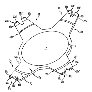
In a further preferred embodiment, IOL 10 includes four haptics 32-35
extending
ftoin optic periphery 16. Each haptic terminates in a free end 32a-35a wliich
extends in
an anterior direction relative to the elongated section 32b-35b of the
respective haptic.
With xeference to Fig. 6, in a preferred embodiment,haptic free ends 32a-35a
extend
6
CA 02588962 2007-05-18
WO 2006/054178 PCT/IB2005/003676
relative to the elongated section of the respective baptic at an angle "B" of
about 15 to
40 and more preferably about 33 . Each haptic free end 32a-35a may also taper
from a
maximum thickness T3 to a minimum tliiclcness T4. The tip of each haptic free
end may
be beveled with a bevel angle "C" of about 10 to 20 and more preferably
about 18 .
When in an unstressed state (i.e., the state when no compressive foxces are
being
applied to the IOL), the elongated section.s 32b-35b of hapties 32-35
preferably extend
substa-ntially straight although a sliglit curvature is possible. The free
ends 32a-35a each
have a length preferably about a quarter of the length of the respective
elongated sections
32b-35b although this may vary. In a further preferred embodiment of the
invention, the
proximal haptic length (closer to periphery 16) has a thickness T, larger
tlian the
tli.ickztess Tz of a respective distal haptic length (closer to the free end)
(see Fig. 4). In a
preferred embodiment, T2 is between about 0.10 and 2.0mm and more preferably
is
about 0.15xnm, and Tj is between about 0.10 to 2.5mm and more preferably about
0.2mm. In sorn,e embodiments, the thickness decreases by at least 10%. In some
einbodiments, the thickness decreases by at least 15%. In some embodiments,
the
thiekn.ess decreases by at least 20%. Preferably,l:he reduction in thickness
between the
proximal end of the haptic and the distal end of the baptic is approximately
in the range
10%-60%, and in some embodiments in the range 15%-40%, and in some embodiments
in the range 20%-30%, and in some embodiments is approximately 25%.
A thickness decrease is measured excluding any portion of the lengtli of a
haptic
including a PCO, sharp edge 13. Additionally, the tY-iclrness decrease is
measured
excluding any free end, thickness features, sucli frce end features may
include a localized
increase in thicltness to interfaee with the eoapsular bag. For example, in
some
embodiments, tlie reduetion in thickness is measured over a central portion of
7
CA 02588962 2007-05-18
WO 2006/054178 PCT/IB2005/003676
approximately 65% of ihe length of the haptxcs (e.g., excluding the PCO sharp
edge may
exclude approximately 5%-15% of the distance along the proximal portion of the
haptic,
and excluding the free end nZay exclude approximately 20% of the distal
portion of the
baptic). Accordingly, it is to be appreciated that, a proxitnal end and/or a
distal end may
not be the absolute ends of the haptics.
Althougb the eznbodimctat of an IOL 10 illustrated in FIGs. 4 and 6 includes
haptics having a single step in thickness, haptics having two, three or four
or more steps
may also be implemented, For exarnple the haptic illustrated in FIG. 7A
includes two
steps 136a and 136b forming three regions 137a, 137b and 137c having
thiclcn,ess of TI,
T2 and T3, respectively. It is to be appreciated iliat in the illustrated
embodirncaat each of
the regions comprises a substantial portion of the length of the haptic (e.g.,
greater than
approximately 15%, 20% or 30% o:Cthe k-aptic length). The regions may be equal
in
lengih. For example, in an ernbodiment having two steps the regions may be
approximately three equal regions comprzsing approximately 33% of the haptic
length.
In an embodiment having tliree steps the regions may be four equal regions of
approximately 25%. Althougli the above haptics were discussed as having
regions of
equal length, it is to be apprecaated that some embodiments have regions of
substantial
but unequal lengths on a haptic. Additionally, as illustrated in FIG. 7B, in
embodiments
having two or more steps, at least one step 13 6c may be formed on an anterior
surface of
tlze haptic, and at least one step 136d formed on postexior surface of the
haptic. In some
embodiments the thickness is monotonieally decreasing between the proximal end
and
the distal end. The terna "monotonieally decreasing" means that thickness does
not
increase when progressing from the proximal end to the distal end but may have
one or
more regions of constant thickness.
s
CA 02588962 2007-05-18
WO 2006/054178 PCT/IB2005/003676
Iri some embodiments, the reduction in thickness decreases smoothly (i.e.,
there
is no step) along the entire length or along one or more of the regions. In
some
embodiments, as illustrated in FIG. 7C, the reduction in tbickness is linear.
In such
einbodinnents, the anterior and/or posterior side of the haptic may liav'e a
slope relative to
a centerline 140 that extends along the length of the haptic and through the
center of the
tbickness of the haptic. In some emboditn.ents having a linear reduction in
thickness, the
reduction when proceeding from the proximal end to the distal end is greater
than 15%;
and in some embodiments the reduction in ihickness is greater than 25%. It is
to be
appreciated that aspects of the invention directed to haptics having a reduced
thickness as
described in any of the embodiments described above may also have an angled
free end,
a baptic having a concave anterior surface, and/or fingers as described
herein.
Referring to Figures 2,4, 5 and 6, the unstressed state of the exemplary
embodiment of an IOL 10 is shown in solid lines. When implanted into the eye's
capsular bag 20, the optic 11 is preferably aligned substantially along the
optical axis OA
with the haptics 32-35 extending radially outward therefrom. The free ends 32a-
35a of
the haptics are positioned toward or near the bag equator 20b. As the bag 20
begins to
shrink in the weeks and months following surgery, radial compressive (stress)
forces are
applied to the IOL 10 and particularly along the haptYVs 32-35 thereo:f. In
response, the
hapties 32-35 will ilex with the direction of movement thereof being
controlled by the
free ends 32a-35a thereof.
The stressed state of the IOL 10 is shown in dashed lines in Figures 2, 5 and
6.
The llexing movement proceeds in this predicted manner due to the unique
baptic
configurations of the invention. Thus, wh.en a compressive force is applied at
the
anteriorly extending free ends 32a-35a of the haptics, they respojnd by
flexing further in
9
CA 02588962 2007-05-18
WO 2006/054178 PCT/IB2005/003676
an anterior direction. That is, they flex anteriorly and thczeby decrease
their radius of
curvature from Ri to R2 where R2 is less than R, (Figs. 2 and 6)_
In a first aspeet, the haptics will flex anteriorly under a radial compressive
force
since the free ends 32a-35a already extend in an anterior direction (in their
unstressed
state as shown in solid lines) and are tlius biased to continue flexing in
this direction
under compressive forces (to their stressed state as shown in dashed lines) as
opposed to
the opposite direction (i.e., posteriorly).
In a second respect, the haptics will flex anteriorly under a radial
compressive
force since the proximal haptic length Ep (closer to periphery 16) has a
tliickness Ti
larger than the tlhiclcness T2 of a respective distal haptic length IId
(closer to the free end)
as stated above. It is therefore practically an impossibility that the baptics
would flex in
the posterior direction under a radial compressive force.
It will thus be appreciated that according to aspects of the i-avention the
anterior
movement of the haptic flexing is initiated at the fxee ends 32a-35a tliereof
As the free
ends 32a-35a flex anteriorly and thereby decrease their radius of curvature,
the elongated
sections32b-35b of the haptics may also begin to flex anteriorly,
predominantly at the
thiinier, distal haptic lengths DL thereof
The direction of haptic flex may also be considered with regard to the
relation
between the plane in which the haptics flex and the plane in which optic 11
lies. More
particularly, the plane in which a respective haptic may flex is indicated at
Pt, while the
optic plane is indicated at P. in Figs. 1 and 2. It is seen in these figures
that these planes
extend generally perpendicular to each other. It may thus be said that the
haptics will flex
in a respective plane Ph that extends generally perpendicular to the plane Po
in which
optic 11 lies.
CA 02588962 2007-05-18
WO 2006/054178 PCT/IB2005/003676
Witli the haptics thus absorbing the compressive forces in the manner
described
above, optic 11 remains substantially aligned along the eye's optical axis OA.
When so
aligned, the geometric center axis GC of the optic 11 is coincident wifli the
eye's optical
axis OA as sliown in Fig. 2. It is noted, however, that perfect alignment may
not always
be achievabl.e due to variations in surgical techniques and capsular size, for
example.
Thus, wlzile prefect alignm,ent is the goal for best optical results, it is
intended that the
term "aligned" herein be interpreted to allow for less than perfect aliginnent
between the
geornetric center of the optic and the eye's optical axis. It is furthermore
noted that
posterior movement of optic 11 is possible (along the optical axis OA),
however, this is
not considered a problenz since fYrm contact between the posterior capsular
wa1120a and
the optic posterior surface 14 is desirable to prevent capsular opacifi.cation
(PCO). In this
regard, optic 11 is provided with a sharp peripheral edge 13 which together
with
posterior capsular wall 20a, creates a barrier to epithelial cell -migration
from the capsular
equator to the optic 11. Lpithelial cell migration is a principal cause of
PCO.
According to another aspeci: of the invention, the haptics may be curved along
their lengths from the proximal end to the distal end, as illustrated in FIGs.
8A or 813.
That is, when iraversing the haptic froni the proximal end of the haptic to
the distal end
of th.e haptic, the lens is curved so as to be concave on the anterior surface
of the haptic:
In sorne embodiments, as illustrated in FIG. 8A, the curvature has a single
curvature
along the entire length of the liaptio from the proximal end to the distal
end.
Altennatively, the haptic inay comprise two or more regions along the length,
each region
having a different cutvature (not shown). In some embodiments, as illustrated
in FIG.
8B, the haptic curvature varies continuously along the length of the haptic.
The
curvature or curvatures along the length of a haptic may be described, for
example, by
11
CA 02588962 2007-05-18
WO 2006/054178 PCT/IB2005/003676
one or more of polynomial curvature, such as a conic curvature (e.g., an
elliptical
curvature, a hyperbolic curvature or a spherical curvature), a series of
planar portions
approXimating a curve, or a curvature described point-by-porint.
In some embodiments, as illustrated in FIGs. 8A and 8B, the anterior surface
and
the posterior surface of the haptic liave substantially the same curvatures as
one another
(the anterior surface being concave and the posterior surface being convex).
For
example, the anterior surface and the posterior surface will have
substantially the same
curvature'if the haptic has a unifortn thickness along its length or if the
thickness
decreases a relatively small amount along its length.
A curvature is determined excluding any portion of the length of a haptic
including a PCO sharp edge 13. Additionally, the curvature of the haptic is
determined
excluding the free end features which may include a localized increase or
decrease in
curvature, for example, to interface with the capsular bag. For example, in
some
embodiments, the radius of curvature is measured over a central portion 820
approximately 65% of the haptics (e.g., excluding the PCO sharp edge 13 may
exclude
approximately 5%-15% of the distance along the baptic, and excluding free end
815 may
exclude approximately 20% of the distat portion of the haptic). It is to be
appreciated
that einbodiments including a curvature as described above predispose a lens
to move
posteriorly upon radial compression resulting from shrinlsir-g of the capsular
bag, and
operates to maintain centration of the lens in a capsular bag. It is to be
appreciated that
aspects of the invention directed to a haptics having a curvature as described
above may
also have an angled free end, a reduced thiclrness, and/or fxmgers as
described herein.
In a fiirther aspect of the invention, the haptic I'Tee ends 32a-35a each
cornprise at
least two spaced fingers 32c,d-35e,d, respectively (Figs. 1, 4 and 5). In some
12
CA 02588962 2007-05-18
WO 2006/054178 PCT/IB2005/003676
embodiments each finger pair extends substantially parallel to each other with
the
extrenie tips 32c',d'-35c',d' tliereof lying in a plane which is generally
perpendicular to
the geometric center axis GC of optic 11. As compressive forces are applied to
the
fingers, the two fingers of a respective haptic may move toward one another to
reduce or
close the space therebetween such as from space St to a space S2 as shown in
Fig. 5.
This moveinent absorbs particularly those conipressive forces having a vector
component directed i:an.gential,ly to the circumference of the lens such as
represented by
vectors VR , for example, that are created by the dynamics of the shrinlcing
capsular bag.
In particular, the fingers are deformable toward one another in a tangential
direction. It
is to be appreciated the tangential force addressed by the fingers is
perpendicular to the
radial force addressed by the angle and curvature of the haptics discussed
above. This
aspect of the invention is particularly advantageous when combined with a thin
lens
design in that it also helps maintain the slructural stability of the lens.
This aspect is also
advantageous when combined a structwre capable of adapting to radial
compressive
forces such as a hapt7ic k-aving an anteriorly curved surface, a haptic that
decreases in
tliiclrness from the proximal end to the distal end andlox haptics having
angled free ends
as described above. It is to be appreciated that, when used in such a
combination, the lens
is capable of maintaining stability in the presence of botli tangential and
radial forces
which may result from capsular bag shrinkage.
Although the embodiment of an IOL illustrated in Figure 1 has IJ-sliaped notch
N, the groove may have any suitable sliape. For example, the IOL illustrated
in Figure
9A includes a bulb-shaped notch S, Also, although the exemplaty embodiment of
an
IOL illustrated in Figure 1 has two fingers, TOT.s may have three, four, five
or more
13
CA 02588962 2007-05-18
WO 2006/054178 PCT/IB2005/003676
fiingers. For example, the IOL illustrated in. Figvre 9B includes three
fingers 832 and two
notches T.
Tn a-further preferred embodiment, the tips of the Bngers 32c,d-35c,d extend
at
an angle of between about 10 and 50 relative to the remairider of the free
end, and more
preferably extends at an angle of between about 20 and 40 , and most
preferably extends
at an angle of about 33 relative to the remainder of a respective free end.
It will be
noticed that the angle corner may be located approximately mid-way along the
space S i
between each finger pair although this may vary.
It will thus be appreciated that haptics according to aspects of the invention
are
capable of absorbing compiessive forces having a multitude of vectors such as
those
created by 1:he dynamics of a shrinldng capsular bag while the IOL optic 11
remains
substantially aligned along the eye's optical axis as intended.
14