Note: Descriptions are shown in the official language in which they were submitted.
CA 02589003 2007-05-24
WO 2006/060264 PCT/US2005/042563
1
METHOD OF DETECTING AND CORRECTING RELAY TACK WELD FAILURES
FIELD OF THE INVENTION
[0001] The present invention relates generally to relay control systems and
methods,
and more particularly to relay control systems and methods that address faulty
relay
operation.
BACKGROUND OF THE INVENTION
[0002] Relays have long been used in both consumer and commercial appliances
and.
machinery to provide automated or electrically controlled switching operation.
One of the
benefits of such relays is that they allow the use of "low level" signals to
switch "high level"
power. That is, a typical relay includes at least one coil that pulls in or
controls the
switching of the main relay contacts. For some types of magnetically held
relays, de-
energization of the relay coil will cause the main relay contacts to open
under action of a
spring force or other mechanical bias. Such held relays, therefore, require
that the coil be
energized during the period of main contact closure (or opening in a normally-
closed relay
configuration). Another type of single coil relay is known as a cutthroat
relay. In this relay
the state of the contacts is transitioned by momentarily energizing the relay
coil. That is, to
open the relay if the contacts are currently closed, the relay coil is pulsed.
Within the relay,
a cutthroat mechanism switches over so that upon subsequent energization of
the relay coil
the contacts will then re-close. Latching type relays utilize two separate
coils, one
dedicated to open the contacts, and one dedicated to close the contacts. That
is, if the
contacts are currently closed, the trip coil may be pulsed to cause the
contacts to open.
Once the contacts have opened, there is no need to maintain energization of
the trip coil. To
close the contacts from this state, the close coil is energized.
[0003] While these relays utilize an electronic control signal to control the
position of
the main relay contacts, the contacts themselves are mechanical structures. As
such, they
are bound by the laws of physics. Because of this, their physical properties
must be taken
into account in the control circuitry and control logic for the relays. As
illustrated in Fig. 8,
one of the physical properties that must be taken into account when utilizing
relays is the
time lag between the energization of the relay coil (depicted as line 800) and
the actual
transition of the relay contacts (as illustrated by the relay output voltage
line 802). As may
be seen from this Fig. 8, the relay control circuitry energizes the relay coil
at time To. Once
CA 02589003 2007-05-24
WO 2006/060264 PCT/US2005/042563
2
energized, the relay coil establishes a magnetic flux that will, in this
example, close the
relay contacts. The actual contact closure takes place at time Ti. As
indicated by line 802,
however, the initial closing at time Ti is typically followed by a short
period of relay contact
bounce before the relay contacts maintain their closed state at time T2. This
mechanical
bounce is a result of the kinetic energy that is generated as the relay
contacts are accelerated
toward one another under the influence of the magnetic flux generated by the
relay coil.
[0004] A different, but somewhat related phenomenon of intermittent contact
bounce
occurs between the relay contacts when they are opened. During the trip
operation of an
electrically held relay, the relay coil is de-energized and the relay contacts
are allowed to be
opened by a mechanical bias force, often provided by a spring. However, the
flux generated
by the relay coil is not extinguished immediately. As such, there is some
initial contention
between these two opposing forces. Additionally, the current flow through the
relay
contacts also plays a part in the slight bounce or chatter during the trip
operation. With
current flowing through the relay contacts, initial separation of the contacts
results in an arc
being drawn between the two contacts which tends to pull the contacts
together. Until the
spring force can overcome these opposing forces, inconsistent opening may
occur for a
short time. Similar bounce or chatter is also seen for the other types of
relays described
above that require coil energization to open the contacts.
[0005] While the delay in opening and closing the relay contacts can be
compensated in
the control circuitry and logic, the contact bounce phenomenon occasionally
results in a
mechanical failure of the relay. Specifically, and especially when supplying
high in-rush
capacitive, motor, lamp, and overloads through the relay, the relay bounce
results in an arc
being drawn between the relay contacts at each bounce. As a result of this
arcing, the metal
that forms the relay contacts may become molten at a small and localized
point. When the
contacts come back together, this molten material of the relay contacts may
form a small
tack weld. This tack weld prevents the relay contacts from opening under
normal operation.
A similar situation may occur during the opening of the relay coil, especially
with relays
that utilize separate trip coils due to the time required to establish
sufficient flux to separate
the contacts in high current applications. This problem may become especially
acute in
applications that use coil suppression techniques in the driver circuitry of
such trip coils.
[0006] As a result of the relay tack weld failure, the relay contacts remain
closed, and
the load to which they are connected cannot be de-energized. If this problem
happens to the
control relay of, for example, a compressor in a refrigerator, the compressor
cannot be de-
CA 02589003 2007-05-24
WO 2006/060264 PCT/US2005/042563
3
energized once the temperature in the freezer or fresh food compartment has
reached its
desired set point. This will result in the temperature set point being
exceeded by continued
operation of the compressor. As a result, the owner will be forced to make a
service call to
correct this problem.
[0007] Because the actual area of the relay contact surface that is tack
welded is
typically very small, the removal of the relay by service personnel to
investigate the cause
of the failure often results in breaking this physical tack weld. When the
relay is
subsequently tested, it may operate normally. This may be reported as a "could-
not-
duplicate" failure or may result in further, needless investigation of other
potential causes
for failure. Often, this may lead to a costly replacement of the control board
that contains
the relay driver circuitry. This may well result in needless loss of time and
additional
expense for the consumers, not to mention the frustration that may be caused
by the initial
failure of the relay itself.
[0008] There exists, therefore, a need in the art for a relay control method
that can
detect a relay tack weld failure, and attempt to correct this failure before
service personnel
needs to be called.
BRIEF SUMMARY OF THE INVENTION
[0009] In view of the above, it is an object of the present invention to
provide a new and
improved relay control method that overcomes the above and other problems
existing in the
art. More particularly, it is an objective of the present invention to provide
a new and
improved relay control method that is capable of detecting a relay tack weld
failure and that
will attempt to resolve this failure without user intervention to preclude the
necessity of
scheduling a service call.
[0010] In view of these objects, it is a feature of the present invention to
sense the relay
tack weld failure through direct sensing of the circuitry involved. It is an
alternate feature
of the present invention to detect such a relay tack weld failure indirectly
by sensing a
system parameter that shows consequences of the failure condition. Once
detected, it is a
further feature of the present invention to attempt to electromechanically
resolve the tack
weld failure automatically. It is also a feature of the present invention to
limit the automatic
CA 02589003 2007-05-24
WO 2006/060264 PCT/US2005/042563
4
attempts to resolve the tack weld failure to prevent other failures within the
relay control
system.
[0011] In one embodiment of the method of the present invention, the existence
of the
relay tack weld failure is first detected. This detection may be the result of
sensing relay
circuit parameters, such as output voltage or current flow after the relay has
been
commanded to the trip. Auxiliary contacts of a relay may be used in one
embodiment.
Alternatively, this step of detecting the relay tack weld failure may be
accomplished by
sensing other parameters that may be affected by continued operation of the
load which the
relay controls. In an embodiment of the present invention wherein the method
is
implemented in a refrigerator for control of a compressor, this indirect
sensing may include
the step of sensing the compartment temperature. If the compartment
temperature continues
to drop after the compressor has been commanded off, a relay tack weld may
have occurred.
In other embodiments where the method of the present invention is implemented
in a
furnace, continued presence of flame or continued rise in ambient temperature
sensed by the
thermostat may also provide indication of a possible relay tack weld failure.
[0012] In a preferred embodiment of the present invention, the method attempts
to
recycle the relay. Preferably the number of recycles attempted is limited to
prevent other
damage from occurring in the relay control circuitry. For a magnetically held
relay, the
close coil is energized and de-energized a number of times in an attempt to
break the tack
weld. If the relay opens, the recycling of the relay is discontinued to
preclude subsequent
tack welding of the contacts. In an embodiment of the present invention
implemented for
control of a cutthroat relay, the relay coil is pulsed a number of times in an
attempt to break
the relay tack weld. In an embodiment of the present invention to control a
latching type
relay having both close and trip coils, the method may pulse the trip coil a
number of times,
or may alternatively pulse the close and trip coil a number of times in an
attempt to break
the relay tack weld. In any of these embodiments, recycling of the relay is
stopped once the
contacts open.
[0013] Other aspects, objectives and advantages of the invention will become
more
apparent from the following detailed description when taken in conjunction
with the
accompanying drawings.
CA 02589003 2007-05-24
WO 2006/060264 PCT/US2005/042563
BRIEF DESCRIPTION OF THE DRAWINGS
[0014] The accompanying drawings incorporated in and forming a part of the
specification illustrate several aspects of the present invention, and
together with the
description serve to explain the principles of the invention. In the drawings:
[0015] FIG. 1 is a simplified illustration of a refrigerator utilizing a relay
to control a
compressor in which the method of the present invention has particular
applicability;
[0016] FIG. 2 is a simplified flow diagram illustrating one aspect of an
embodiment of
the method of the present invention;
[0017] FIG. 3 is a simplified flow diagram illustrating another aspect of an
embodiment
of the method of the present invention;
[0018] FIG. 4 is a graphical illustration of various control parameters that
illustrate
operation of the method of the present invention when controlling a
magnetically held relay;
[0019] FIG. 5 is a graphical illustration of various control parameters that
illustrate
operation of the method of the present invention when controlling a cutthroat
relay;
[0020] FIG. 6 is a graphical illustration of various control parameters that
illustrate
operation of the method of the present invention when controlling a latching
relay;
[0021] FIG. 7 is a graphical illustration of various control parameters that
illustrate
operation of an alternate embodiment of the method of the present invention
when
controlling a latching relay; and
[0022] FIG. 8 is a simplified graphical illustration of the control and
closing of a typical
relay.
[0023] While the invention will be described in connection with certain
preferred
embodiments, there is no intent to limit it to those embodiments. On the
contrary, the intent
is to cover all alternatives, modifications and equivalents as included within
the spirit and
scope of the invention as defined by the appended claims.
CA 02589003 2007-05-24
WO 2006/060264 PCT/US2005/042563
6
DETAILED DESCRIPTION OF THE INVENTION
[0024] While the relay control method of the present invention may be
implemented in
any system that utilizes electromechanical relays, the following description
will describe the
operation of this method in the context of a method of controlling a
compressor control
relay in a consumer refrigerator. However, such an environment is utilized for
illustrative
purposes only, and is not limiting to the scope of the invention as defined by
the appended
claims. Additionally, while other environments in which the method finds
applicability
may be mentioned or discussed herein, such other implementations are also
provided to give
the reader context and aid in the understanding of the invention, and should
also not be
taken as limiting the scope of the invention.
[0025] As illustrated in FIG. 1, a consumer or commercial refrigerator 100
typically
includes some type of controller 102 that includes control logic, sensing
circuitry, and,
output control circuitry to control, for example, the compressor control relay
104. This
compressor control relay 104 allows the controller 102 to turn the compressor
106 on and
off by energizing the relay coil 108 to cause the main relay contacts 110 to
close. In this
exemplary embodiment, the relay 104 is a magnetically held relay that requires
the coil 108
to be energized in order for the power to be provided to the compressor 106
via the contacts
110. When the coil 108 is de-energized by the controller 102, a mechanical
bias force will
result in the relay contacts I 10 opening to de-energize the compressor 106.
However, while
this exemplary embodiment is described as using a magnetically held relay,
those skilled in
the art will recognize that other types of relays may also be utilized in such
a system to
provide control of the compressor 106, as will be discussed more fully below.
The
controller 102 may also include temperature sensors 112, 114 for the fresh
food
compartment 116 and the freezer compartment 118, respectively. The controller
102 may
also include a relay circuit parameter sensor. As illustrated in FIG. 1, this
sensor may be a
current sensor 120, relay output voltage sense line 122, and/or relay
auxiliary contact sense
124, etc.
[0026] In such an environment as that illustrated in FIG. 1, the compressor
control logic
programmed into controller 102 will utilize the temperature sensors 112, 114
to determine
when the compressor 106 needs to be turned on to maintain the fresh food
compartment 116
and the freezer compartment 118 at their desired preset temperatures. Once the
controller
102 determines that the compressor 106 needs to be turned on to provide
additional cooling
CA 02589003 2007-05-24
WO 2006/060264 PCT/US2005/042563
7
to the refrigerator 100, it commands its driver circuitry to energize the
relay coil 108. This
will result in the relay contacts 110 (and also the auxiliary contacts 124) to
close. Once
closed the compressor 106 is energized though contacts 110 and begins the
cooling process
for the refrigerator 100.
[0027] Once the controller 102 determines that the desired amount of cooling
has been
provided by the compressor 106, it commands its driver circuitry to de-
energize relay coil
108. Under normal circumstances, the mechanical bias of the magnetically held
relay 104
will cause the relay contacts (and also the auxiliary contacts 124) to open.
Once the relay
contacts 110 are opened, the compressor 106 is de-energized. However, if a
relay tack weld
failure has occurred either during the initial closing of contacts 110 or
during the attempted
tripping of contacts 110, the compressor 106 will continue to be energized,
and will
continue to provide cooling to the refrigerator 100.
100281 In an attempt to overcome this problem, the method of the present
invention
detects abnormal operation when the relay is commanded to open. As illustrated
in FIG. 2,
the method of the present invention first determines if a relay turn off
condition has
occurred at step 200. If not, the method illustrated in FIG. 2 ends and allows
the controller
102 to continue cycling through its other control algorithms. If, however, a
relay turn off
condition has occurred as determined by decision block 200, such as the
temperature
reaching its desired set point, the controller 102 then operates to turn the
relay off at step
202. As discussed above with regard to the magnetically held relay, this will
result in the
driver circuitry of controller 102 de-energizing the relay coil 108. The
method of the
present invention then sets a relay check timer at step 204, and clears a
relay pulse timer at
step 206.
[0029] The relay check timer is utilized in an embodiment to the present
invention to
establish a period of time after which a relay tack weld failure may reliably
be detected.
Depending on the type of sensor utilized to determine the relay tack weld
failure, this check
timer period may vary. For example, if a voltage, current or auxiliary contact
sense is used,
this relay check timer may be short, ranging from a few milliseconds to a few
seconds.
However, in embodiments of the present invention that utilize indirect
sensing, such as
temperature sensing within the refrigerator 100, the relay check timer may
need to be much
longer, possibly on the order of several minutes. Such timing may easily be
determined by
those skilled in the art based on the settling time of the parameter being
monitored during
normal operation of the system.
CA 02589003 2007-05-24
WO 2006/060264 PCT/US2005/042563
8
[0030] The relay pulse timer establishes the pulse duration during which the
coil will be
energized in an attempt to free the tack welded relay contacts. This pulse
duration may be
relatively short, and need provide energization only until sufficient magnet
flux can be
generated by the coil to cause a bias force on the contacts by the magnet
flux. While longer
duration pulses may be utilized, it is the mechanical shock provided by the
magnet flux that
is likely to break the tack weld, not establishing a steady state held
position by continuing to
energize the relay coil. Those skilled in the art will recognize that the use
of such a relay
pulse timer may not be needed for other types of relays, such as cutthroat
relays or
mechanical latching relays, as typical relay controllers for these types of
relays already only
provide a pulse of sufficient duration under normal operation to transition
the relay contacts.
In other words, the normal relay control provides its own relay pulse duration
mechanism.
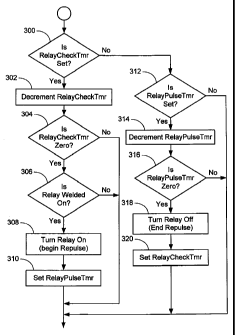
[0031] FIG. 3 illustrates the tack weld failure determination method and the
relay
recycling procedure that attempts to clear the relay tack weld. Initially this
embodiment of
the method of the present invention checks to determine if the relay check
timer has been
set by the relay control method of FIG. 2 at decision block 300. If the relay
check timer has
been set, meaning that the relay control of FIG. 2 has attempted to trip open
the relay, the
method proceeds to decrement the relay check timer at step 302. Decision block
304 then
checks to see whether the relay check timer has reached zero or its time-out
condition. If it
has not, this method ends and allows the controller 102 to continue cycling
through its other
control algorithms. However, once the relay check timer has reached zero as
determined by
decision block 304, a check is made to see if the relay is welded in its
closed or on position
at decision block 306. As discussed above, this determination may be made by
utilizing
various sensors (direct or indirect) to determine if the load remains powered
due to a tack
weld failure of the relay.
[0032] If it is determined that the relay has a tack weld failure, then the
method will turn
on the relay to begin its repulse at step 308. To control the duration of the
pulse in this
embodiment utilizing a held relay, the method then sets the relay pulse timer
at step 310.
For other embodiments in which the normal relay control provides an
appropriate pulse
width to control the relay, this step is not required. Such may be the case,
e.g., for cutthroat
and latching type relays. If at decision block 306 it is determined that the
relay has properly
opened its contacts, this method will end and allow the controller 102 to
continue cycling
through its other control algorithms.
CA 02589003 2007-05-24
WO 2006/060264 PCT/US2005/042563
9
[0033] Returning to decision block 300, if it is detennined that the relay
check timer is
not set, either because the relay has not been commanded off or because the
relay check
timer has been decremented to zero and the repulse has begun, decision block
312 is then
used to determine if the relay pulse timer is set. If the relay pulse timer
has not been set,
this means that the relay has not been commanded off and this method ends to
allow the
controller 102 to continue cycling through its other control algorithms.
However, if
decision block 302 determines that the relay pulse timer has been set (via
step 310), then the
method begins decrementing the relay pulse timer at step 314 to control the
pulse duration.
Decision block 316 then checks the relay pulse timer to determine whether it
has expired. If
it has not, this method ends to allow the controller 102 to continue cycling
through its other
control algorithms. However, once the relay pulse timer has reached zero as is
determined
by decision block 316, step 318 will turn off the energization to the relay
coil 108 to end the
repulse at step 318. The method of the present invention then sets the relay
check timer at
step 320 to once again check to see if the relay tack weld failure has been
corrected and the
relay has opened.
[0034] As illustrated in FIG. 3, there is no limitation to the number of times
that the
repulse will be attempted to try and overcome the tack weld failure. That is,
if the relay
contacts remain welded together, the embodiment of the present invention
illustrated in
FIG. 3 will continue to repulse the relay after the expiration of the relay
check timer and
after confirming that the relay is still closed, until the contacts open.
However, in an
alternate embodiment of the present invention, a limitation to the number of
repulse
attempts may be set as desired. In such an embodiment, a counter may be
implemented to
count each repulse attempt until the maximum desired number of repulse
attempts has been
reached. The method of the present invention may then also include error
reporting
identifying the relay tack weld failure. If the relay is opened by the method
of the present
invention, however, there is no need to report the failure because such tack
welds are
occasional occurrences. However, if desired, the method of the present
invention may also
provide error reporting upon the first occurrence of the tack weld failure,
whether or not this
problem is overcome by any of the methods of the present invention.
[0035] Having now described the operation of an embodiment of the method of
the
present invention, attention is directed to FIG. 4. This FIG. 4 graphically
illustrates the
relay tack weld failure problem and the operation of the method of the present
invention to
break the tack weld in the refrigerator example. Specifically, FIG. 4
illustrates the operation
of an embodiment of the method of the present invention usable with a
magnetically held
CA 02589003 2007-05-24
WO 2006/060264 PCT/US2005/042563
relay. In this figure, line 400 represents the state of the energization of
the relay coil, line
402 illustrates the state of the compressor control command to turn the
compressor on and
off, line 404 illustrates the operational state of the compressor, line 406
represents the
temperature within the refrigerator 100, and line 408 represents the current
supplied to the
compressor through the relay contacts.
[0036] As illustrated in FIG. 4, the compressor is initially de-energized and
the
temperature illustrated by line 406 is rising within the refrigerator 100. At
time T, the
temperature 406 reaches the control point at which the controller 102 signals
via the
compressor control 402 that the compressor is to be turned on. The relay coil
400 is
energized to close the relay contacts to, in turn, energize the compressor.
Energization of
the compressor is illustrated by the spike in current at time T1 on line 408.
Once the
compressor is running, the temperature 406 within refrigerator 100 decreases.
[0037] At time T2 the temperature 406 within refrigerator 100 has reached its
lower
threshold. The compressor control 402 is then taken low by controller 102,
indicating that
the compressor is to be turned off. Since FIG. 4 illustrates the usage of a
magnetically held
relay, the relay coil energization is also turned off at this time T2.
However, because a relay
tack weld failure exists, the compressor is not de-energized at time T2, and
the temperature
406 continues to drop within the refrigerator 100. Once the relay check timer
has expired as
illustrated at time T3, the method of the present invention operates to re-
energize or repulse
the relay coil in an attempt to break the relay tack weld. The duration of the
repulse at time
T3 is controlled by the relay pulse timer discussed above. As illustrated in
this FIG. 4,
however, this first repulse is not successful in breaking the relay tack weld
as illustrated by
the continued energization of the compressor. Therefore, at time T4 the relay
check timer
has again expired and the coil is then repulsed. Once the relay pulse timer
has expired at
time T5 the relay coil is de-energized. As illustrated in this FIG. 4, this
second repulse was
successful in breaking the relay tack weld and the compressor is de-energized
at time T5
once the second repulse ends and the relay contacts open.
[0038] FIG. 5 illustrates the same information for lines 402-408, but utilizes
a cutthroat
type relay. As is recognized by those skilled in the art, a cutthroat relay is
a latching type
relay having a single relay coil that is used to both open and close the relay
contacts based
on the current state of the relay contacts. As illustrated in this FIG. 5,
initially the
compressor is off and the temperature is rising within refrigerator 100. At
time T, the
controller 102 commands the compressor on and the relay coil 500 is energized
to close the
CA 02589003 2007-05-24
WO 2006/060264 PCT/US2005/042563
11
relay contacts and energize the compressor. During compressor energization the
temperature drops within refrigerator 100. At time T2 the lower threshold
temperature is
reached and the controller 102 turns off the compressor control command 402.
The relay
coil is pulsed at time T2 in an attempt to open the relay contacts and de-
energize the
compressor.
[0039] However, due to a relay tack weld failure the contacts fail'to open.
Therefore, at
time T3 after the expiration of the relay check timer, the relay coil is again
pulsed in an
attempt to break the relay tack weld. Because the relay contacts did not open,
the cutthroat
mechanism does not operate. Therefore, repulsing of the relay coil will again
attempt to
simply open the contacts. At time T4 the relay coil is again pulsed after the
expiration of the
relay check timer has determined that the relay contacts are still welded
closed. On this
second repulse attempt the relay tack weld is broken and the compressor is de-
energized at
time T4.
[00401 FIG. 6 illustrates a further alternate embodiment of the present
invention for use
with a latching type relay having both a trip and a close coil as represented
by lines 600 and
602, respectively. As with the previous two figures, FIG. 6 illustrates the
same initial
conditions and the same command to energize the compressor at time TI. Also,
at time T2
the compressor control command indicates that the compressor is to be de-
energized and the
trip coil 600 is energized. However, due to the relay tack weld failure the
contacts fail to
open and the compressor remains energized. At time T3, after expiration of the
relay check
timer, the close coil is first energized followed by an energization of the
trip coil in an
attempt to break loose the relay tack weld. Unfortunately, FIG. 6 illustrates
that this first
attempt is unsuccessful in de-energizing the compressor. Therefore, at time T4
after
expiration of the relay check timer, the close and trip coils are again
energized in sequence.
Once the trip coil has been energized at time T5, the compressor is de-
energized because
this second attempt is successful at breaking the relay tack weld.
[0041] FIG. 7 illustrates an alternate embodiment of the present invention for
use with a
latching type relay. In this embodiment the close coil is not energized prior
to attempting to
again trip the relay by energizing the trip coil as discussed above in FIG. 6.
Specifically,
upon the initial attempt to de-energize the compressor at time T2 in response
to the
compressor control command 402 indicating that the compressor is to be de-
energized, the
relay contacts fail to open due to the relay tack weld failure. At time T3
after the expiration
of the relay check timer the trip coil 600 is again energized in an attempt to
break loose the
CA 02589003 2007-05-24
WO 2006/060264 PCT/US2005/042563
12
relay tack weld. Unfortunately, this first repulse attempt is unsuccessful as
evidenced by
the continued energization of the compressor. The trip coil is again energized
to repulse the
relay at time T4 after the expiration of the relay check timer. This time the
repulse attempt
is successful in breaking loose the relay tack weld and the compressor is de-
energized at
time T4.
[0042] All references, including publications, patent applications, and
patents, cited
herein are hereby incorporated by reference to the same extent as if each
reference were
individually and specifically indicated to be incorporated by reference and
were set forth in
its entirety herein.
[0043] The use of the terms "a" and "an" and "the" and similar referents in
the context
of describing the invention (especially in the context of the following
claims) is to be
construed to cover both the singular and the plural, unless otherwise
indicated herein or
clearly contradicted by context. The terms "comprising," "having,"
"including," and
"containing" are to be construed as open-ended terms (i.e., meaning
"including, but not
limited to,") unless otherwise noted. Recitation of ranges of values herein
are merely
intended to serve as a shorthand method of referring individually to each
separate value
falling within the range, unless otherwise indicated herein, and each separate
value is
incorporated into the specification as if it were individually recited herein.
All methods
described herein can be performed in any suitable order unless otherwise
indicated herein or
otherwise clearly contradicted by context. The use of any and all examples, or
exemplary
language (e.g., "such as") provided herein, is intended merely to better
illuminate the
invention and does not pose a limitation on the scope of the invention unless
otherwise
claimed. No language in the specification should be construed as indicating
any non-
claimed element as essential to the practice of the invention.
[0044] Preferred embodiments of this invention are described herein, including
the best
mode known to the inventors for carrying out the invention. Variations of
those preferred
embodiments may become apparent to those of ordinary skill in the art upon
reading the
foregoing description. The inventors expect skilled artisans to employ such
variations as
appropriate, and the inventors intend for the invention to be practiced
otherwise than as
specifically described herein. Accordingly, this invention includes all
modifications and
equivalents of the subject matter recited in the claims appended hereto as
permitted by
applicable law. Moreover, any combination of the above-described elements in
all possible
variations thereof is encompassed by the invention unless otherwise indicated
herein or
CA 02589003 2007-05-24
WO 2006/060264 PCT/US2005/042563
13
otherwise clearly contradicted by context.