Language selection

Search

Patent 2589078 Summary

Third-party information liability

Some of the information on this Web page has been provided by external sources. The Government of Canada is not responsible for the accuracy, reliability or currency of the information supplied by external sources. Users wishing to rely upon this information should consult directly with the source of the information. Content provided by external sources is not subject to official languages, privacy and accessibility requirements.

Claims and Abstract availability

Any discrepancies in the text and image of the Claims and Abstract are due to differing posting times. Text of the Claims and Abstract are posted:

  • At the time the application is open to public inspection;
  • At the time of issue of the patent (grant).
(12) Patent: (11) CA 2589078
(54) English Title: DISPENSING PERSONAL CARE PRODUCTS
(54) French Title: SYSTEME DISTRIBUTEUR DE PRODUITS D'HYGIENE PERSONNELLE
Status: Granted and Issued
Bibliographic Data
(51) International Patent Classification (IPC):
  • B65D 83/14 (2006.01)
(72) Inventors :
  • SALEMME, JAMES L. (United States of America)
(73) Owners :
  • THE GILLETTE COMPANY
(71) Applicants :
  • THE GILLETTE COMPANY (United States of America)
(74) Agent: GOWLING WLG (CANADA) LLP
(74) Associate agent:
(45) Issued: 2011-05-10
(86) PCT Filing Date: 2005-12-07
(87) Open to Public Inspection: 2006-06-22
Examination requested: 2007-05-31
Availability of licence: N/A
Dedicated to the Public: N/A
(25) Language of filing: English

Patent Cooperation Treaty (PCT): Yes
(86) PCT Filing Number: PCT/US2005/044125
(87) International Publication Number: WO 2006065586
(85) National Entry: 2007-05-31

(30) Application Priority Data:
Application No. Country/Territory Date
11/013,229 (United States of America) 2004-12-15

Abstracts

English Abstract


A dispensing system comprising: a pressurized canister (24) having top
defining an opening, a bottom, and a generally cylindrical side wall, a
flexible bag (10), disposed within the canister (24), containing a component
to be dispensed from the dispensing system, a valve assembly, in fluid
communication with the bag (10), sealing the opening of the canister (24) and
including a valve defining an outlet through which the component can exit the
dispensing system, and an actuator, configured to open the valve in response
to actuation by a user, wherein the bag (10) includes an upper portion (12)
and a tapered lower portion (14), the lower portion (14) having a sidewall
that tapers away from the side wall of the canister (24) as the bag (10)
approaches the bottom of the canister (24).


French Abstract

L~invention concerne un système distributeur, comprenant un récipient sous pression (24) comprenant un haut définissant une ouverture, un fond et une paroi latérale généralement cylindrique, une poche souple (10), disposée à l~intérieur du récipient (24), contenant un composant à distribuer du système distributeur, un ensemble de valve, en communication fluide avec la poche (10), obturant de façon étanche l~ouverture du récipient (24) et comportant une valve définissant une sortie par laquelle le composant peut s~échapper du système distributeur, et un actionneur, configuré pour ouvrir la valve lorsqu~il est actionné par un utilisateur. Le système distributeur est caractérisé en ce que la poche (10) comporte une partie supérieure (12) et une partie inférieure rétrécie (14), la partie inférieure (14) présentant une paroi latérale qui se rétrécit en s~écartant de la paroi latérale du récipient (24) à mesure que la poche (10) s~approche du fond du récipient (24).

Claims

Note: Claims are shown in the official language in which they were submitted.

-6-
Claims
1. A dispensing system comprising
a pressurized canister having a top defining an opening, a bottom, and a
generally
cylindrical side wall,
an outer bag disposed within the canister containing a first component to be
dispensed
from the dispensing system,
an inner bag, disposed within the outer bag, containing a second component to
be
dispensed,
a valve assembly, in fluid communication with the inner and outer bags,
sealing the
opening of the canister and including a valve defining outlets through which
the components can
exit the dispensing system, and
an actuator, configured to open the valve in response to actuation by a user,
and
wherein the inner and outer bags are configured such that the space between
the inner bag
lower portion and outer bag lower portion is less than the space between the
inner bag upper
portion and outer bag upper portion, so that less material is likely to be
trapped in the outer bag
lower portion upon collapsing of the bags.
2. The dispensing system of claim 1, wherein each of the outer bag lower
portion and the
inner bag lower portion is tapered radially inwardly and away from the side
wall of the canister.
3. The dispensing system of claim 1, wherein the valve assembly comprises a
single, unitary
valve stem.
4. The dispensing system of claim 3, wherein the valve stem comprises a female
valve stem.
5. The dispensing system of claim 1, wherein the inner bag includes a tapered
upper portion,
having a sidewall that tapers away from the side wall of the canister as the
bag approaches the
top of the canister.

-7-
6. The dispensing system of claim 1, wherein the inner bag includes a threaded
neck.
7. The dispensing system of claim 1, wherein the outer bag includes an upper
edge that is
crimped onto a rim of the canister.
8. The dispensing system of claim 1, wherein the inner and outer bags are
sized and
configured such that the volume of the first component is substantially the
same volume of the
second component.
9. The dispensing system of claim 8, wherein the inner and outer bags each
include an upper
portion and a tapered lower portion, the lower portion having a sidewall that
tapers away from
the side wall of the canister as the bag approaches the bottom of the
canister.
10. The dispensing system of claim 9, wherein the upper portion of the inner
bag is tapered
inwardly, so that the inner bag is generally diamond-shaped in cross-section.

Description

Note: Descriptions are shown in the official language in which they were submitted.


CA 02589078 2007-05-31
WO 2006/065586 PCT/US2005/044125
DISPENSING PERSONAL CARE PRODUCTS
This invention relates to dispensing personal care products, e.g., shaving
preparations, and more particularly to dispensing products from a pressurized
can.
In some cases, personal care compositions such as shaving preparations are
dispensed from pressurized containers that include an outer canister, an inner
bag
containing the composition, and a propellant between the container and the
bag. The
propellant applies pressure to the outer wall of the bag, forcing the
composition out of the
bag through a valve at the container outlet when the user presses an actuator
button on the
container. If the composition includes two components that must be separated
prior to
dispensing, the container may include a second bag disposed within the inner
bag, i.e., the
container may be a "bag-in-bag" system in which the propellant acts
simultaneously on
both bags.
While such containers generally work well, some of the composition may
get trapped in the bottom of the bag(s), and thus to be wasted rather than
being delivered
to the consumer and requiring the manufacturer to fill the container with an
extra volume
of the composition just so that the advertised volume will be dispensed.
Moreover, in a
bag-in-bag system, more material may be trapped in the outer bag than the
inner bag, and
thus the ratio of the two components generally may not remain constant as the
contents of
the container are dispensed.
The present invention features bags for pressurized containers of the type
described above. The bags have a shape that prevents material from being
trapped in the
bottom of the bag, which reduces residue and allows more product to be
delivered to the
consumer rather than wasted. In a bag-in-bag system, the shape prevents
material from
getting trapped on the bottom of the outer bag, which generally allows the
ratio of the two
components to remain substantially constant as the contents of the container
are
dispensed. The bags are also easy to assemble into the outer canister during
manufacturing and easy to fill.
In one aspect, the invention features a dispensing system including (a) a
pressurized canister having top defining an opening, a bottom, and a generally
cylindrical

CA 02589078 2007-05-31
WO 2006/065586 PCT/US2005/044125
-2-
side wall, (b) a flexible bag, disposed within the canister, containing a
component to be
dispensed from the dispensing system, (c) a valve assembly, in fluid
communication with
the bag, sealing the opening of the canister and including a valve defining an
outlet
through which the component can exit the dispensing system, and (d) an
actuator,
configured to open the valve in response to actuation by a user. The bag
includes an
upper portion and a tapered lower portion, the lower portion having a sidewall
that tapers
away from the side wall of the canister as the bag approaches the bottom of
the canister.
In another aspect, the invention features a dispensing system including (a)
a pressurized canister having top defining an opening, a bottom, and a
generally
cylindrical side wall, (b) an outer bag, disposed within the canister,
containing a first
component to be dispensed from the dispensing system, (c) an inner bag,
disposed within
the outer bag, containing a second component to be dispensed, (d) a valve
assembly, in
fluid communication with the inner and outer bags, sealing the opening of the
canister and
including a valve defining outlets through which the components can exit the
dispensing
1s system, and (e) an actuator, configured to open the valve in response to
actuation by a
user. The inner and outer bags each include an upper portion and a tapered
lower portion,
the lower portion having a sidewall that tapers away from the side wall of the
canister as
the bag approaches the bottom of the canister.
In some implementations, the valve assembly comprises a single, unitary
valve stem, e.g., a female valve stem.
Generally, the products described herein are pressurized, i.e., the contents
of the container are under pressure, for example pressure applied by a
propellant or by a
mechanical force such as a spring.
The details of one or more embodiments of the invention are set forth in
the accompanying drawings and the description below. Other features and
advantages of
the invention will be apparent from the description and drawings, and fi=om
the claims.
FIG. 1 is a side view of a bag according to one embodiment of the
invention.
FIG. 1 A is a detail view of area A of the bag shown in FIG. 1.

CA 02589078 2007-05-31
WO 2006/065586 PCT/US2005/044125
-3-
FIG. 2 is a side view of the bag of FIG. 1 disposed in a canister, with the
front half of the canister cut away to show the bag.
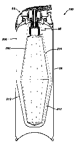
FIG. 3 is a cross-sectional view of a bag-in-bag two component dispensing
system according to one embodiment of the invention. FIG. 3A is an enlarged
detail view
of area A in FIG. 3.
FIG. 4 is a perspective view showing the inner bag of the dispensing
system shown in FIG. 3.
RefeiTing to FIGS. 1-lA, a bag 10 includes an upper, straight-walled
portion 12 and a lower, contoured portion 14. A transition area 16 separates
the straight-
walled portion and the contoured por tion. The transition area 16 generally
has a radius of
curvature R1 of about 20 mm to about 200 mm, preferably about 30 to 80 mm.
Generally, the larger R1, the easier it is for the bag to collapse,
facilitating both delivery
of product to the user and assembly of the bag into the can. However, making
R1 larger
also tends to reduce the volume of the bag, requiring a larger (typically
longer) canister to
contain the same volume of product. If desired, the transition area may be
omitted, and
the bag may contour smoothly from the top to bottom. However, this geometry
may
reduce the volume of the bag to an undesirable extent in some cases.
Alternatively, the
bag may include two or more transition areas, at which the contour angle of
the bag
changes, if desired.
The contoured portion 14 terminates in a base portion 18. The contoured
portion tapers at an angle that is governed by the length of the bag that is
permitted by the
packaging requirements, the volume that the bag must contain, and the desired
shape of
the base portion 18.
Preferably, the base portion is smoothly rounded and relatively narrow,
e.g., width W is within about 5 mm of the diameter of the canister opening,
to facilitate
insertion of the bag into the canister while maximizing the volume of the bag.
Width W
is measured at the change in radius of curvature of the bag that is closest to
the bottom of
the bag. It is preferred that the base portion not come to a sharp point, to
avoid trapping
of material in the base portion and to maximize the volume of the bag.
Generally, it is

CA 02589078 2007-05-31
WO 2006/065586 PCT/US2005/044125
-4-
preferred that the radius of curvature R2 of the base portion be from about 10
mm to
about half of width W (W/2).
Refei7=ing to FIG.. lA, it is generally preferred that the shoulder 20 of the
bag, adjacent the neck 22, conform as closely as possible to the contour of
the inner wall
of the canister 24 (FIG. 2) in this area. Preferably, at any point along the
shoulder of the
bag, the radius of curvature (R10, R20) of the bag 10 is within about 20%,
more
preferably within about 10%, of the radius of curvature of the canister 24
at the same
point. It is also generally preferred that the transition area 21 between the
neck and
shoulder be smoothly curved, as shown. In some embodiments, the neck 22' may
be
to threaded (e.g., as shown in FIGS. 3, 3A, and 4), in order to provide a
secure connection of
the bag to a valve 26 (FIG. 3) that controls dispensing of material from the
canister.
Bag 10 may be formed of any desired flexible sheet material. Typically,
the bag is formed of a material that may be blow-molded, e.g., a polymer such
as
polyethylene or polypropylene, and has a wall thickness of about 0.1 to about
0.5 mm.
Bag-in-bag systems, discussed above, utilize a bag-in-bag ai7=angement
such as that shown in FIG. 3. The bag-in-bag system 180 includes an outer bag
200,
similar to bag 10 described above, and an inner bag 202 disposed within the
outer bag.
The top edge 201 of outer bag 200 is crimped to a rim 203 of the canister 24.
The inner
bag 202 includes a neck 22' that is mounted in threaded engagement to a valve
The two
bags contain first and second components of a composition to be dispensed,
maintaining
the components separate during storage.
A lower portion 210 of the outer bag 200 is contoured to match the contour
of the inner bag 202. In particular, the lower portion 210 tapers inwardly in
the same
manner as the corresponding lower portion 212 of the inner bag, so that the
walls of the
two bags are generally parallel in this area. This configuration tends to
prevent material
from getting trapped in the bottom of the outer bag, which reduces residue and
allows
more product to be delivered to the consumer rather than wasted. Because less
material is
trapped in the bottom of the outer bag, the ratio of the two components
generally remains
constant as the contents of the container are dispensed. Preferably, in bag-in-
bag systems,
the contour of the lower portion of the inner bag follows the contour of the
lower portion

CA 02589078 2007-05-31
WO 2006/065586 PCT/US2005/044125
-5-
of the outer bag as closely as possible.
As shown in FIGS. 3 and 4, the inner bag may include a tapered upper
portion 214 as well as a tapered lower portion, so that the bag is generally
diamond-
shaped in cross-section. This shape allows the two bags to contain
substantially the same
volume of the two components. If it is desired that the two bags contain
different relative
amounts of the components, the shape of the upper portions of the two bags can
be
adjusted accordingly.

Representative Drawing
A single figure which represents the drawing illustrating the invention.
Administrative Status

2024-08-01:As part of the Next Generation Patents (NGP) transition, the Canadian Patents Database (CPD) now contains a more detailed Event History, which replicates the Event Log of our new back-office solution.

Please note that "Inactive:" events refers to events no longer in use in our new back-office solution.

For a clearer understanding of the status of the application/patent presented on this page, the site Disclaimer , as well as the definitions for Patent , Event History , Maintenance Fee  and Payment History  should be consulted.

Event History

Description Date
Common Representative Appointed 2019-10-30
Change of Address or Method of Correspondence Request Received 2018-01-10
Grant by Issuance 2011-05-10
Inactive: Cover page published 2011-05-09
Inactive: Final fee received 2011-02-25
Pre-grant 2011-02-25
Notice of Allowance is Issued 2011-02-08
Letter Sent 2011-02-08
Notice of Allowance is Issued 2011-02-08
Inactive: Approved for allowance (AFA) 2011-01-28
Inactive: Adhoc Request Documented 2010-10-19
Inactive: Delete abandonment 2010-10-19
Inactive: Abandoned - No reply to s.30(2) Rules requisition 2010-07-26
Amendment Received - Voluntary Amendment 2010-07-13
Inactive: S.30(2) Rules - Examiner requisition 2010-01-26
Amendment Received - Voluntary Amendment 2009-09-23
Inactive: S.30(2) Rules - Examiner requisition 2009-03-25
Inactive: Cover page published 2007-08-21
Letter Sent 2007-08-17
Inactive: Acknowledgment of national entry - RFE 2007-08-17
Inactive: First IPC assigned 2007-06-20
Application Received - PCT 2007-06-19
National Entry Requirements Determined Compliant 2007-05-31
Request for Examination Requirements Determined Compliant 2007-05-31
All Requirements for Examination Determined Compliant 2007-05-31
Application Published (Open to Public Inspection) 2006-06-22

Abandonment History

There is no abandonment history.

Maintenance Fee

The last payment was received on 2010-11-19

Note : If the full payment has not been received on or before the date indicated, a further fee may be required which may be one of the following

  • the reinstatement fee;
  • the late payment fee; or
  • additional fee to reverse deemed expiry.

Please refer to the CIPO Patent Fees web page to see all current fee amounts.

Owners on Record

Note: Records showing the ownership history in alphabetical order.

Current Owners on Record
THE GILLETTE COMPANY
Past Owners on Record
JAMES L. SALEMME
Past Owners that do not appear in the "Owners on Record" listing will appear in other documentation within the application.
Documents

To view selected files, please enter reCAPTCHA code :


To view images, click a link in the Document Description column. To download the documents, select one or more checkboxes in the first column and then click the "Download Selected in PDF format (Zip Archive)" or the "Download Selected as Single PDF" button.

List of published and non-published patent-specific documents on the CPD .

If you have any difficulty accessing content, you can call the Client Service Centre at 1-866-997-1936 or send them an e-mail at CIPO Client Service Centre.


Document
Description 
Date
(yyyy-mm-dd) 
Number of pages   Size of Image (KB) 
Representative drawing 2007-05-31 1 4
Description 2007-05-31 5 219
Drawings 2007-05-31 5 84
Claims 2007-05-31 3 92
Abstract 2007-05-31 2 65
Cover Page 2007-08-21 2 39
Claims 2009-09-23 2 72
Claims 2010-07-13 2 57
Representative drawing 2011-02-03 1 9
Cover Page 2011-04-13 2 46
Acknowledgement of Request for Examination 2007-08-17 1 177
Notice of National Entry 2007-08-17 1 204
Courtesy - Certificate of registration (related document(s)) 2007-08-17 1 104
Commissioner's Notice - Application Found Allowable 2011-02-08 1 162
PCT 2007-05-31 3 81
Correspondence 2011-02-08 1 52
Correspondence 2011-02-25 2 51