Note: Descriptions are shown in the official language in which they were submitted.
CA 02589286 2013-02-28
- 1 -
AN IMPROVED WORK BENCH
Technical Field
This invention relates to improvements in a work
bench.
Background to the Invention
A prior art work bench is shown in attached figure 1.
This work bench is described in published international
patent specification W001/78950.
In figure 1, a power tool in the foLm of a power saw
12 is mounted to a base structure 14 which in turn is
mounted on four castor wheels 16. Workpiece supports are
provided in the form of stands 26 fitted with rollers 58
mounted between roller supports 59. In use, a workpiece
(not shown) can be moved along rollers 58. Saw 12 can be
rotated to cut across the workpiece at a desired angle by
rotating base structure 14 on its wheels 16.
End stop 48 can be used to locate the workpiece with
respect to the saw to repetitively cut lengths of material
to the same length. This is achieved by abutting the end
of the workpiece against the end stop 48.
Summary of the Invention
In a first aspect the present invention provides a
work bench including: at least two workpiece supports, the
two supports are positioned at intervals along an elongate
member and define a substantially horizontal plane in
which a workpiece can move; a mounting for a power tool,
the mounting is affixed to the elongate member and can
rotate about an axis that is substantially parallel to the
length of the elongate member; a ground engaging member
CA 02589286 2007-05-25
WO 2006/056004 PCT/AU2005/001148
- 2 -
which supports the power tool mounting at a point spaced
away from the elongate member; and adjustment means for
adjusting the effective length of the ground engaging
member.
By use of the above arrangement, the length of the
leg can be adjusted to provide adjustment of the
rotational position of the power tool mounting with
respect to the elongate member. This allows the position
of the power tool to be adjusted so that the base of the
tool can be brought into a plane that is substantially
parallel to the plane of the underside of the workpiece.
This aids the accuracy of machining of the workpiece when
using the bench. In the prior art bench of figure 1, it
had been found that, when used on uneven ground, the
orientation of the plane in which bed of power saw 12 lies
could change as the saw was rotated.
The workpiece supports may include rollers.
The elongate member may be in the form of a staff.
The mounting may be affixed to the elongate member by
receiving the elongate member in a channel.
The mounting may rotate about the elongate member due
to elastic deformation of the elongate member.
The adjustment means may include a clamp that can
clamp the ground engaging member at a desired position.
In a second aspect the present invention provides a
work bench including: at least two workpiece supports, the
supports are spaced apart and define a substantially
horizontal plane in which a workpiece can move; a mounting
for a power tool; an adjustable end stop spaced away from
the power tool mounting; and two adjustable side stops are
provided proximate to the end stop and are arranged to
CA 02589286 2011-03-29
- 3 -
abut either side of a workpiece to locate the workpiece
with respect to the end stop.
In this arrangement, the side stops guide the
workpiece to correctly abut the end stop. The operator
does not need to walk along to the end stop to inspect
whether alignment is correct thus saving time and effort.
The workpiece supports may include rollers.
The workpiece supports may be spaced apart along an
elongate member.
The side stops may include threaded portions to allow
for adjustment.
The side stops may include locknuts to maintain the
side stops in a desired position.
In a third aspect, the present invention provides a
workpiece support including: a roller and at least two
roller supports; the roller can be mounted in the roller
supports in upper and lower positions; in the lower
position the periphery of the roller lies below the top
edge of the roller supports and in use the roller supports
operate to guide a workpiece; and in the upper position
the periphery of the roller lies above the top edge of the
roller supports.
By use of this arrangement, when in the upper
position the rollers can support a workpiece that is wider
than the distance between roller supports. The prior art
work bench of figure 1 is limited to conveying workpieces
that are narrower than the distance between roller
supports.
The roller may be mounted by engaging the spindle of
the roller with holes in the roller supports.
The first and second positions may be defined by the
positions of holes in the roller supports.
CA 02589286 2011-03-29
,
- 3a-
In yet a further aspect, a work bench including: at
least two workpiece supports, the workpiece supports being
positioned at intervals along an elongate member and defining
a substantially horizontal plane adapted to allow a workpiece
to move therein; a mounting for a power tool, the mounting
being affixed to the elongate member and rotatable about an
axis that is substantially parallel to the length of the
elongate member, the mounting extending at an angle from the
elongate member; a ground engaging member extending
downwardly from the mounting from a position spaced away from
the elongate member; and adjustment means for adjusting the
effective length of the ground engaging member.
CA 02589286 2007-05-25
WO 2006/056004 PCT/AU2005/001148
- 4 -
Brief Description of the Drawings
An embodiment of the present invention will now be
described, by way of example only, with reference to the
accompanying drawings, in which:
Figure 1 is a perspective view of a prior art work
bench;
Figure 2 is a perspective view of a work bench
according to an embodiment of the present invention;
Figures 2A, 2B and 2C are detail views of elements of
the work bench of figure 2;
Figure 3 is an alternative perspective view of the
work bench of figure 2;
Figure 4 is an underside perspective view of the
power tool mounting of the work bench of figure 2;
Figure 5 is a perspective view of a saw bench
according to a second embodiment of the present invention;
Figure 6 is an underside perspective view of the
power tool mounting of the work bench of figure 5; and
Figure 7 depicts in detail the adjustable side stops
of figure 2.
Detailed Description of the Preferred Embodiment
Unless otherwise indicated, all parts referred to in
the following description are formed from square hollow
section (SHS) steel. The embodiment of a work bench that
will now be described has been designed for easy assembly
and disassembly. This allows the bench to be disassembled
for easy transportation to a desired location such as a
building site.
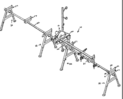
Referring to figures 2, 3 & 4, a work bench 10 is
shown. Work bench 10 includes five workpiece supports in
the form of roller assemblies 57. Each roller assembly 57
CA 02589286 2007-05-25
WO 2006/056004
PCT/AU2005/001148
- 5 -
includes a single roller 58. Each roller 28 rotates about
a spindle 61 which engages with holes 60 provided opposite
one another in roller supports 59.
Three of the roller assemblies 57 include stands 26
which are positioned at intervals along an elongate member
in the form of staff 24. Staff 24 is made up of a number
of segments which fit together end to end in a telescopic
fashion and can be clamped together at each join by
tightening a wingbolt. Providing the staff 24 in segments
allows for the staff to be disassembled to short lengths
to facilitate transportation. Each stand includes a
channel in the form of a sleeve formed from a length of
square hollow section steel that is dimensioned to
accommodate staff 24. Each sleeve is located underneath
roller assembly 57 which receives staff 24 and clamps to
staff 24 by way of a threaded wingbolt. By loosening the
wingbolts, the roller assembly can be slid along staff 24
to a desired position. The top edges of rollers 58 define
a plane in which a workpiece can be moved along the
rollers. In figure 2, a workpiece in the form of a plank
of wood is shown. The underside of the workpiece lies in
the plane defined by the top edges of the rollers 58.
A mounting 20 for a power tool is provided and is
affixed to staff 24 by inserting staff 24 through sleeve
102 and tightening wingbolts 104 (see figure 4). In the
drawings, a power saw 12 is shown affixed to mounting 20.
Mounting 20 is tightly clamped to staff 24 and is able to
rotate about the axis of the length of staff 24 to a
certain degree due to rotational elastic deformation of
parts of the bench and in particular by elastic
deformation of staff 24. Other parts that may elastically
deform to a degree are mounting 20, sleeve 102, and stands
26.
CA 02589286 2007-05-25
WO 2006/056004 PCT/AU2005/001148
- 6 -
A ground engaging member in the form of leg 106
supports mounting 20 at a point spaced away from staff 24
by being fixed to mounting 20 by insertion into sleeve 108
and tightening wingbolt 110 (see figure 4) to clamp leg
106 in position. The effective length of leg 106 can be
adjusted by slackening wingbolt 110 and sliding leg 106
with respect to sleeve 108, the wingbolt 110 is
retightened at the desired position. This adjustment
affects the height of the rear part of mounting 20 and
thus provides for adjustment of the rotational position of
mounting 20 and hence saw 12 with respect to rollers 58.
In this way, the rotational position of saw 12 may be
adjusted to bring the bed of saw 12 into a plane that is
substantially parallel to the plane in which the workpiece
moves. Having the power tool properly aligned with the
workpiece assists in achieving accurate machining of the
workpiece. This feature is particularly helpful if the
work bench is being used on uneven ground.
Referring to figures 5 & 6, an alternative embodiment
of a work bench 110 is shown. This embodiment differs
from the above described embodiment in that an alternative
power tool mounting 120 is provided. Mounting 120 allows
for rotation in a horizontal plane as will now be
described. Referring to figure 6, mounting 120 is made up
of two major components being clamp 121 and tray 126. Two
segments of staff 24 are shown being segments 24A 24B.
Clamp 121 is affixed to staff 24 by inserting staff
segments 24A and 24B into sleeve 122. A sight hole 125 is
provided to allow an operator to ensure that segments 24A
and 24B meet approximately in the middle of sleeve 122.
When segments 24A and 24B are in the correct position wing
bolts 124 are tightened to retain them in position.
CA 02589286 2007-05-25
WO 2006/056004
PCT/AU2005/001148
- 7 -
Each of segments 24A and 24B is made up of a length
of SHS steel with a depth limiting collar 25 provided near
to one end. As an alternative method of assembly, the end
with the depth limiting collar 25 can be inserted into
sleeve 122. This allows other components to be slid onto
the free end of the segment. This also obviates the need
for sight hole 125, as the collar 25 dictates the depth of
insertion of a segment into channel 122. After one
segment has been inserted in this manner, the end of the
segment inside channel 121 itself dictates the depth of
insertion of another segment into the other end of channel
121.
Tray 126 is attached to clamp 121 by way of a single
bolt 128. Thus, tray 126 can rotate with respect to clamp
121 about the axis of bolt 128. In use, a power tool such
as saw 12 is mounted to tray 126. This arrangement allows
for rotation of the power tool in a horizontal plane. It
can be seen in figure 5 that the tray has been rotated to
the side to achieve an angular cut with saw 130. This
feature is particularly useful if the power tool being
used does not itself provide for pivotal movement in a
horizontal plane- The saw 12 shown in figures 2 & 3
itself provides for this movement by way of rotatable
turntable 13.
When dismantling the work bench for transport, the
power tool mounting 20, 120 can be left attached to the
underside of the power tool. In this way the mounting 20,
120 serves to protect the base of the power tool from
accidental damage that might be caused in transit.
Referring to figures 2, 2B and 7, work bench 10
includes an end stop 48. End stop 48 is held in a pivotal
mounting 49. Pivotal mounting 49 includes two main
CA 02589286 2007-05-25
WO 2006/056004 PCT/AU2005/001148
- 8 -
component being a sleeve that fits telescopically about
staff 24, and a clamp that holds end stop 48. The sleeve
can by slid along staff 24 to any desired position and is
secured in place by tightening two wingbolts provided on
the clamp with engage with staff 24.
The clamp can pivot with respect to the sleeve. This
allows the end stop 48 to be tilted away from the
workpiece when necessary. The pivotal assembly pivots in
a vertical plane that is perpendicular to the direction of
travel of the workpiece. The ability to tilt the end stop
away from the workpiece is particularly useful when making
the final part of a cut using an abrasive cutting disc as
otherwise, the workpiece can become jammed against the end
stop with associated risk of damaging the abrasive cutting
disc.
A bolt 140 and locknut is provided on the end of end
stop 48. This allows fine adjustment of the positioning
of workpiece when butted against end stop 48.
Work bench 10 further includes two adjustable side
stops in the form of threaded rods 130, 132 which are held
in threaded portions 134 of bracket 136 (see figure 7).
Locknuts 138 are provided to allow side stops 130, 132 to
be secured in a desired position. Bracket 136 is fitted
to staff 24 by way of clamp 51. Leg 137 of bracket 136 is
formed from round bar steel and includes means for
aligning bracket with respect to the workpiece in the form
of a flat portion (not shown) on the leg 137. The flat
portion locates in the clamp which holds bracket 136 to
perpendicularly align bracket 136 with respect to the
workpiece. Clamp 51 may be loosened and moved along staff
24 to any desired position.
As can be seen in figure 2, the side stops 130, 132
are adjusted to abut either side of workpiece (in this
CA 02589286 2007-05-25
WO 2006/056004 PCT/AU2005/001148
- 9 -
case, a plank of wood). The side stops 130, 132 go to
ensuring that the workpiece is accurately positioned
before cutting.
A roller assembly 57 and roller 58 is provided
proximate end stop 48 to support the workpiece. Roller
assembly includes a sleeve which receives staff 24 and can
be clamped in position with a wingbolt. Thus, the
wingbolt can be loosened to allow repositioning of the
roller assembly 57 by sliding it along staff 24.
The spindle 61 of each roller 58 is spring loaded.
Pressing both ends of the spindle towards one another
allows the spindle and roller to be removed from roller
supports 59.
Two pairs of holes 60 are provided on each stand (see
figure 2C). Each pair of holes defines a position for the
spindle 61 of a roller 58. The lower pair of holes
defines a lower position for roller 58. The rollers 58
are shown in the lower position in figure 2. In this
position the periphery of roller 58 lies below the top
edge of the roller supports 59 and in use the roller
supports 59 operate to guide a workpiece. In the upper
position, the periphery of the roller 58 lies above the
top edge of the roller supports 59. In the upper position
the roller can be used to convey a workpiece that is wider
than the roller such as a sheet of material.
Additional pairs of holes 60 may be provided in
roller supports 59 to allow mounting of the roller between
the upper and lowermost positions. This can be used to
adjust the height of rollers 58 to accommodate the
operating height of various power tools that might be
attached to mounting 20.
CA 02589286 2013-02-28
- 10 -
In the above described embodiments workpiece supports
were provided in the form of rollers 58. Similarly, other
suitable supports could be used that allow for movement of
a workpiece.
In the above described embodiments adjustment means
for adjusting the effective length of leg 106 was provided
by allowing sliding movement of leg 106. Other means
could be employed such as providing a telescopic portion
of the leg, or providing a screw threaded foot on leg 106.
In the above described embodiments the rollers could
be moved from an upper to a lower position by using an
appropriate pair of holes 60. Other means of moving the
rollers could be used such as holding the ends of spindles
61 in adjustable mountings that can be adjusted up or down
by travelling on screw threads.
In the above described embodiment, square hollow
section steel was used to form staff 24, and square
sleeves were provided on associated components to allow
them to be fitted to staff 24. Similarly, other steel
sections could be used such as a rectangular section. A
round section staff with round section sleeves is less
desirable, because this arrangement does not provide
positive rotational engagement between the staff and the
sleeves and so the stability of the work bench may be
reduced.
Any reference to prior art contained herein is not to
be taken as an admission that the information is common
general knowledge, unless otherwise indicated.
Finally, it is to be appreciated that various
alterations or additions may be made to the parts
previously described without departing from the scope of
the present invention.