Note: Descriptions are shown in the official language in which they were submitted.
CA 02589290 2007-05-18
WO 2006/056011 PCT/AU2005/001778
A POWER SUPPLY CONNECTION APPARATUS
Field of the Invention.
The present invention relates to power supply sockets and in particular
to power supply sockets that offer enhanced safety to users and third parties.
Background Art.
Electricity sockets are commonly available and come in a wide variety
of fortns. Perhaps the most commonly seen electricity sockets are the wall-
mounted
sockets that allow a user to access the mains power supply for electrically
powered
accessories such as kitchen equipment, vacuum cleaners and whitegoods.
These wall sockets generally include a backing plate with the electrical
contacts and connecting by wiring to the mains power supply and they also have
a
cover member to cover the attachment means. The backing plate has a plurality
of
openings in which the electrical contacts are located and which receive the
tines of the
power plug of the apparatus. When the plug is inserted into the socket, the
contacts
engage the tines but the power generally does not flow until a switch is
activated.
One problem with the wall mounted sockets is that if a small elongate
conductive member is inserted into the openings in the socket, the power can
flow
regardless of whether or not the switch has been activated. This is a widely
recognized
problem and many solutions have been proposed in the past. Generally these
solutions
relate to preventing the insertion of the conductive member into the openings
by
providing covers or similar for the openings or the socket in general.
Similar problems are encountered when using power boards and the
like which allow multiple power plugs to be used with a single power outlet.
For many years, the power point has been a device attached to the wall
with electrical currents freely available with the flick of a switch. Tbis
makes it an
inviting target for children to stick objects into its holes. Also another
problem with
age and continued use, the switches tend to break allowing electrical current
to flow
into the switch which will cause an electric shock.
Further, the provision of switches to allow and prevent the flow of
electricity to the socket do not always completely isolate the power flow from
the
electrical contacts. The switches themselves also make the outlets less
aesthetically
pleasing.
CA 02589290 2007-05-18
WO 2006/056011 PCT/AU2005/001778
2
It will be clearly understood that, if a prior art publica.tion is referred to
herein, this reference does not constitute an admission that the publication
forms part
of the common general knowledge in the art in Australia or in any other
country.
Summary of the Invention.
The present invention is directed to a power supply socket apparatus
which may at least partially overcome at least one of the abovementioned
disadvantages or provide the consumer with a useful or commercial choice.
In one form, the invention resides in a power supply connection
apparatus including a housing having at least one first contact member in
communication with a power supply, at least one rotary member mounted for
rotation
relative to said housing, the rotary member including at least one second
contact
member, the rotary member operably movable between a first condition to align
the
respective contact members and a second condition in which the respective
contact
members are not aligned.
The connection apparatus may have a socket (female) or plug (male)
configuration or both, with a socket associated with either the at least one
first contact
member or the at least one second contact member and a plug associated with
the
other of the at least one first contact member or the at least one second
contact
member.
The power supply socket apparatus of the present invention will
preferably be available in different configurations including single socket,
double
socket and four socket configurations. In fact, there may be any number of
sockets
provided in a single housing. Where the apparatus is provided in multiple
rotating
socket member configuration, more than one rotary socket member may be
associated
with a single power supply.
The power supply socket apparatus of the invention may be provided as
a wall mounted apparatus, for example as a permanent fitting such as a "power
point"
or alternatively in a portable configuration, for example as a power board or
the like.
When provided in the portable configuration, the power supply socket
apparatus will generally have multiple sockets in a single housing which can
be linked
to a mains power supply by a single plug and socket. The power supply socket
CA 02589290 2007-05-18
WO 2006/056011 PCT/AU2005/001778
3
apparatus of the invention may also find application as the female or socket
end of
electrical extension lead or the like.
The power supply socket apparatus includes a housing. The housing
will typically be formed of an electrically non-conductive material and a good
example of a material is a plastic material. The plastic material may be rigid
or
flexible as required but will generally be substantially rigid or at least
dimensionally
stable. The housing will be shaped according to its application, for example a
wall
outlet housing will generally be flatter whereas an electrical extension lead
female end
will generally be shaped to allow manipulation by a user's hand and will
therefore be
more bulbous.
There will typically be more than one first contact member and more
than one second contact member and most suitably, each will include a set of
contact
members.
The power supply socket apparatus preferably includes a first set of
contact members in communication with a power supply, the contact members
typically being electrical contact members. The at least one first contact
member is
associated with the housing and will generally be located within the housing.
There
will generally be at least a pair of contact members. The number and
configuration of
the contact members will generally be determined according to the
configuration
required by the governing body of the country in which the power supply socket
apparatus is sold or used. For example, Australia uses a Type I, three pin
electrical
socket. The Type I plug has three pins, namely a lower, substantially vertical
"earth"
pin and a pair of upper angled pins, one designated an "active" pin and the
other, a
"neutral" pin. Plugs are sold in Australia which lack the "earth" pin. There
are
therefore, three contact members in a Type I plug and three corresponding
contact
members in a Type I socket. There are however many different types of plug and
socket configurations (at least Types A to M) and the contact configuration
will vary
accordingly.
The at least one first contact member will typically be associated with
at least one fuse. The fuse is generally located within the housing and is
designed to
disrupt the power supply in the case of a power surge to reduce the risk of
appliances
suffering damage particularly by electrical fusion.
CA 02589290 2007-05-18
WO 2006/056011 PCT/AU2005/001778
4
The at least one frst contact member is preferably located in the
housing of the power supply socket apparatus. The contact will typically be in
electrical communication with a power supply, generally a mains power supply,
however an altemative embodiment of the invention may provide for the use of
portable backup power supply.
The housing of the power supply socket apparatus generally has an
opening into which the rotary member fits and the at least one first contact
member
will generally extend to communicate with the opening. Preferably, the at
least one
first contact is accessible via the opening in the housing.
The power supply socket apparatus of the present invention further
includes at least one rotary member mounted for rotation relative to said
housing.
Typically, the rotary member will be removably attachable relative to the
housing by
insertion into the opening in the housing. The rotary member may be changeable
to
allow sockets of different configurations to be used with the apparatus.
The rotary member will generally be or include a socket configuration
to match the plug configuration of the country in which it is sold or used.
The rotary
member will therefore typically be adapted to receive the pin or pins of a
power plug
therein. The rotary member will preferably include openings therein to receive
pins of
a plug therein.
The number and configuration of the openings will be provided
according to the outlet configuration in different countries as discussed
above.
The rotary member is generally manufactured of an electrically non-
conductive material such as a plastic material.
The at least one second contact is preferably associated with at least
some of the openings in the rotary member. Again for example, the Australian
Type I
system uses at least two pins, the "active" pin and the "neutral" pin. In this
case, the
second set of contacts will typically be a pair of contacts, one for each of
the "active"
pin and the "neutral" pin. The at least one second contact will typically be
in
electrical communication with the pins of the plug when the plug is fully
inserted into
the openings in the rotary member. The at least one second contact is
typically also
adapted to be aligned with the first set of contacts upon rotation of the
rotary member.
There will generally be a rotation prevention means to prevent over-
CA 02589290 2007-05-18
WO 2006/056011 PCT/AU2005/001778
rotation of the rotary member and to assist with the alignment of the
respective
contacts following rotation. There may be more than one rotation prevention
means,
one to prevent over-rotation of the rotary member in either direction.
The rotary member is operably movable between a first condition to
5 align the respective sets of contact members and a second condition in which
the
respective sets of contact members are not aligned. The first condition is
generally the
"on" condition where power can flow from the power supply, through the aligned
contact members and to the appliance. The second condition is generally the
"off'
condition where power cannot flow to the appliance and further, is not even
available
to the at least one second contact member due to the position of the rotary
member
and the material of construction of the rotary member isolating the at least
one first
contact member from the at least one second contact member.
There will also generally be a locldng arrangement to temporarily lock
the rotary member in the "on" condition. The loclcing arrangement will
typically
include a shaped portion on the rotary member and a correspondingly shaped
portion
on the housing. The loclcing arrangement will suitably maintain the rotary
member in
the "on" condition until either the power plug pins are removed from the
openings
causing the auto-rotation to the "off' condition or until a user rotates the
rotary
member to the "offl" condition manually.
The apparatus of the present invention may suitably further include a
biasing means to bias the rotary meinber into an "off' position where the
respective
contact members are isolated from one another.
Preferably, removal of the power plug pins from the openings in the
rotating member causes the rotary member to auto-rotate to the "off'
condition.
Therefore, means to register that the pins of the plug are in the correct
position in the
openings in the rotary member may typically be provided. The means to register
the
presence of the pins of the plug may be configured such that even partial
removal of
the pins from the openings may be sufficient to cause the auto-rotation to the
"ofP'
condition. The registration means may preferably be located at or adjacent to
the base
of at least one of the openings in the rotary member which receives the pins.
Alternatively, the registration means may be provided on an outer face of the
rotary
CA 02589290 2007-05-18
WO 2006/056011 PCT/AU2005/001778
6
member such that pressure from the plug body may be required to prevent auto-
rotation.
The apparatus of the present invention may suitably further include one
or more cover members which are removably engageable with the housing and/or
the
rotary member to enable a user to choose an aesthetically pleasing colour or
pattern or
combination for the apparatus.
Preferably, the cover members may be changeable so that a user can
change the cover members quickly and easily. The cover members may therefore
have
a click-fit or snap-fit arrangement with the housing and/or rotary members.
Typically,
each rotary member may have a cover member as may the housing.
Another preferably additional feature is the backup power pack which
may be associated with the power supply socket apparatus of the invention.
This
backup power pack may be removably attachable to the apparatus of the present
invention and preferably allows the apparatus to provide backup power to an
appliance in case of power disruption. If the power is cut off, the apparatus
of the
present invention may be manually switchable to draw power from the backup
supply
to allow for a period of operation. The power supply may also switch
automatically.
When the mains power supply is available, the apparatus may be
switchable (either manually or automatically) to the mains power supply. The
backup
power pack may then recharge automatically to be readily available in the next
disruption. Typically, the backup power pack will supply power to the at least
one first
contact member. The backup power pack will typically include a reservoir or
storage
means for storing an electrical charge, typically in the form of one or more
batteries.
Whilst the present invention has been described according to a
preferred embodiment of an electrical connection socket apparatus, it is to be
anticipated that the particular features of the invention may be easily
adapted to other
plug and socket arrangements where a flowing media is present and connections
such
as hydraulic hoses or the like are used.
In another form therefore, the invention may reside in a connection
apparatus including a housing with an inlet adapted for comnaunication with a
flowing
media supply, at least one rotary member mounted for rotation relative to said
housing, the rotary member including an outlet attachable to a connection
portion of a
CA 02589290 2007-05-18
WO 2006/056011 PCT/AU2005/001778
7
flow means along which the flowing media may flow, the rotary member operably
movable between a first condition to allow flow of the media through the
apparatus
and a second condition in which flow is prevented.
According to an altemative preferred embodiment, a heat sensor may
be incorporated into the apparatus. The apparatus may also be provided with an
alert
mechanism. Preferably, the heat sensor may be associated with both the alert
mechanism and the rotary member (or the locking arrangement) such that when
the
heat sensor registers a heat rise above a predetermined level, such as that
occurring
during a fire or similar, the alert mechanism may be activated and the rotary
member
may auto-rotate to the "off' condition effectively disabling the electrical
supply to any
devices which may be connected to the apparatus.
The apparatus may also be provided with a reset switch or other means
to reset the apparatus after disabling in this manner has occurred.
The heat sensor and alert mechanism may be powered from the power
source to which the power supply socket apparatus is connected. This will
usually be
a mains power supply. There may also be a backup power supply, for example a
battery power supply for instances where the mains supply is unavailable.
The heat sensor and alert mechanism may be adapted to communicate
with similar means provided in other power supply socket apparatus provided in
the
same building but in a different location. This may allow the disablement of
all power
supply socket apparatus in a building if one of the heat sensors and alert
mechanisms
is activated. This may be useful, in a situation where a house has multiple
power
supply socket apparatus, and the alert mechanism of one of which is activated
by the
heat sensor, indicating a fire in one room. The activated heat sensor may then
communicate to all other power supply socket apparatus in the house, disabling
all of
them. The communication may be along physical means such as a cable or similar
or
wireless. Alternatively, the heat sensor and alert mechanism may be slaved to
a fire
suppression system such that activation of the heat sensor and the alert
mechanism
may also activate the fire suppression system.
Brief Description of the Drawings.
Various embodiments of the invention will be described with reference
to the following drawings, in which:
CA 02589290 2007-05-18
WO 2006/056011 PCT/AU2005/001778
8
Figure 1 is a plan view of a power supply socket apparatus according to
a preferred embod'unent of the present invention with the cover member removed
and
in the "off' condition.
Figure 2 is a plan view of the power supply socket apparatus as
illustrated in Figure 1 with the cover member in place.
Figure 3 is a plan view of a power supply socket apparatus according to
a preferred embodiment of the present invention with the cover member removed
and
in the "on" condition.
Figure 4 is a plan view of the power supply socket apparatus as
illustrated in Figure 3 with the cover member in place.
Figure 5 is a plan view of a power supply socket apparatus in a twin
socket configuration with the cover member removed and in the "on" condition.
Figure 6 is a plan view of a power supply socket apparatus as
illustrated in Figure 5 with the cover member removed and in the "ofF'
condition.
Figure 7 is a stepwise illustration of a process for changing the visual
appearance of a four way socket configuration of the present invention by
changing
the cover plate and sockets.
Figure 8 is a plan view of a power supply socket apparatus in a twin
configuration with a backup power supply associated therewith.
Figure 9 is a rear elevation view of a power supply socket apparatus
according to an alternative embodiment with a heat sensor incorporated.
Figure 10 is a side view of the power supply socket apparatus
illustrated in Figure 9.
Figure 11 is a front view of the power supply socket apparatus
illustrated in Figure 9.
Detailed Description of the Preferred Embodiment.
According to a preferred embodiment of the present invention, a power
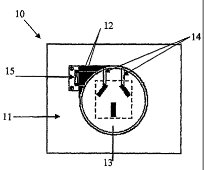
supply socket apparatus 10 is provided.
The power supply socket apparatus 10 illustrated in Figures 1 to 4 is
the simplest configuration having only a single socket. The apparatus 10 has a
housing
11 with a set of first contact members 12 which are in communication with a
power
supply (not shown). There is also a rotary member 13 mounted for rotation
relative to
CA 02589290 2007-05-18
WO 2006/056011 PCT/AU2005/001778
9
said housing 11. The rotary member 13 has a set of second contact members 14,
and
movement of the rotary member 13 between a first condition aligns the
respective
contact members allowing power to flow as illustrated in Figures 3 and 4.
Movement
of the rotary member 13 in the opposite direction activates a second condition
in
which the respective contact members are not aligned as in Figures 1 and 2.
A double socket configuration is illustrated in Figures 5 and 6.
The housing 11 of the apparatus is formed of a plastic material. The
plastic material is generally rigid. The housing 11 is shaped according to its
application, for example a wall outlet housing as illustrated in the Figures
will
generally be flatter whereas an electrical extension lead female end will
generally be
shaped to allow manipulation by a user's hand and will therefore be more
bulbous.
The power supply socket apparatus 10 includes a first set of electrical
contact members 12 in communication with a power supply (not shown).
As discussed above, the number and configuration of the contact
members will generally be determined according to the configuration required
by the
governing body of the country in which the power supply socket apparatus is
sold or
used. For example, Australia uses a Type I, three pin electrical socket. The
Type I
plug has three pins, namely a lower, substantially vertical "earth" pin, and a
pair of
upper angled pins, one designated an "active" pin and the other, a'neutral"
pin.
There are therefore, three contact members in a Type I plug and three
corresponding
contact members in a Type I socket. There are however many different types of
plug
and socket configurations (at least Types A to M) and the contact
configuration will
vary accordingly.
The set of first contact members 12 is associated with a fuse 15. The
fuse 15 is located within the housing 11 and is designed to disrupt the power
supply in
the case of a power surge to reduce the risk of appliances suffering damage.
The power supply socket apparatus of the present invention further
includes at least one rotary member 13 mounted for rotation relative to the
housing 11.
The rotary member 13 is removably attachable relative to the housing 11 by
insertion
into an opening (not shown) in the housing 11.
CA 02589290 2007-05-18
WO 2006/056011 PCT/AU2005/001778
The rotary member 13 has a socket configuration to match the plug
configuration of the country in which it is sold or used. The rotary member 13
includes openings 16 therein to receive pins of a plug (not shown) therein.
The number and configuration of the openings 16 will be provided
5 according to the outlet configuration in different countries as discussed
above.
The rotary member 13 is manufactured of an electrically non-
conductive material such as a plastic material.
The set of second contact members 14 is associated with the openings
16 in the rotary member 13. Again for example, the Australian Type I system
uses at
10 least two pins, the "active" pin and the "neutral" pin. In this case, the
second set of
contacts will be a pair of contacts, one for each of the "active" pin and the
"neutral"
pin. The set of second contact members 14 is in electrical communication with
the
pins of the plug when the plug is fully inserted into the openings in the
rotary member
13. The set of second contact members 14 is also adapted to be aligned with
the first
set of contact members 12 upon rotation of the rotary member 13.
Removal of the power plug pins from the openings 16 in the rotating
member 13 causes the rotary member 13 to auto-rotate to the "off' condition.
Means
to register that the pins of the plug are in the correct position in the
openings 16 in the
rotary member 13 are provided but not illustrated. The means to register the
presence
of the pins of the plug are configured such that even partial removal of the
pins from
the openings 16 is sufficient to cause the auto-rotation to the "off'
condition.
The apparatus 10 of the present invention is provided with cover
members 17a, 17b which are removably engageable with the housing 11 and the
rotary member 13 to enable a user to choose an aesthetically pleasing colour
or pattern
or combination for the apparatus 10.
Illustrated in Figure 7 is a stepwise method for changing the cover
members 17a, 17b of the apparatus 10. Figure 7.1 illustrates the apparatus 10
with the
cover members 17a, 17b for both the housing 11 and each of the rotary members
13
removed. Figure 7.2 illustrates the cover member 17a for the housing 11. In
Figure
7.3, the cover member 17a for the housing 11 has been fitted over the housing
11 and
is attached thereto by a snap-fit arrangement. The individual rotary member
cover
members 17b illustrated in Figure 7.4 are then fitted to the rotary members 13
forming
CA 02589290 2007-05-18
WO 2006/056011 PCT/AU2005/001778
11
the "finished" apparatus 10 in Figure 7.5.
Illustrated in Figure 8 is the apparatus 10 of the present invention
attached to a backup power pack 18. The backup power pack 18 is removably
attachable to the apparatus 10 of the present invention and provides backup
power,
though the apparatus of the invention, to an appliance in case of power
disruption. If
the power is cut off, the apparatus 10 of the present invention is switchable
to draw
power from the backup power pack 18 to allow for a period of operation.
When the mains power supply is available, the apparatus 10 is
switchable (either manually or automatically) to the mains power supply. The
backup
power pack 18 then recharges automatically to be readily available in the next
disruption.
Illustrated in Figure 9 to 11 is an alternative embodiment of the present
invention incorporating a heat sensor 20 and alert mechanism. The heat sensor
is
provided in the housing and stands slightly proud of the housing surface as
seen in
Figures 10 and 11. The heat sensor 20 is provided with electrical power
through a
system of contacts 21 which are maintained in place using screws 22. The heat
sensor
is associated with the socket 13 which is provided with a plurality second
contact
members 14. The socket 13 is retained relative to the housing using a mounting
portion 23 to which the socket 13 is mounted to allow rotation. The mounting
portion
is attached to a rear side of the housing at a mounting point 24.
The housing is provided with a plurality of first contact members 12
which are also mounted relative to the housing by respective mounting portions
24.
The apparatus of this form of the invention is provided with a reset switch 25
to reset
the apparatus after activation of the heat sensor 30 and the alert mechanism.
The heat sensor 20 is associated with both the alert mechanism and the
rotary socket 13 (or the locking arrangement) such that when the heat sensor
20
registers a heat rise above a predeteinuined level, such as that occurri ng
during a fire
or similar, the alert mechanism is activated and the rotary member 13 auto-
rotates to
the "off' condition effectively disabling the electrical supply to any devices
which
maybe connected to the apparatus 10.
In the present specification and claims (if any), the word "comprising"
and its derivatives including "comprises" and "comprise" include each of the
stated
CA 02589290 2007-05-18
WO 2006/056011 PCT/AU2005/001778
12
integers but does not exclude the inclusion of one or more further integers.
Reference throughout this specification to "one embodiment" or "an
embodiment" means that a particular feature, structure, or characteristic
described in
connection with the embodiment is included in at least one embodiment of the
present
invention. Thus, the appearance of the phrases "in one embodiment" or "in an
embodiment" in various places throughout this specification are not
necessarily all
refenring to the same embodiment. Furthermore, the particular features,
structures, or
characteristics may be combined in any suitable manner in one or more
combinations.