Note: Descriptions are shown in the official language in which they were submitted.
CA 02589792 2007-05-31
WO 2006/064243 PCT/GB2005/004850
1
Assessing a network
The present invention relates to the assessment of a network, in particular a
network
having a main line and a plurality of branch lines.
It is known to asses a network having a main line and a plurality of branch
lines by
introducing a test signal into the main line and monitoring a return signal
that arises due to
the reflection or the backscattering of the test signal along the branch
lines. An analysis of
the return signal is performed to ascertain whether there are any faults or
losses along the
branch lines. However, if the return signal suggest a fault, it can be
difficult to determine
which branch line is responsible for the fault. In particular, as the number
of branch lines
increases it becomes increasingly difficult even to detect that there is a
fault.
According to the present invention, there is provided a method of assessing an
optical
network having a main line and a plurality of branch lines, the method
including the steps
of: (i) introducing test signals into the main line, the main line being
coupled to the branch
lines in a branching fashion such that the test signals propagate along the
branch lines; (ii)
imposing a modulation on test signals which propagate along a designated
branch line;
and, (iii) monitoring test signals returned along the main line, the imposed
phase
modulation being detected interferometrically such that the test signals from
the
designated branch line can be distinguished with respect to the signals
returned from
other branch lines.
Because test signals from the designated branch line can be distinguished from
the
signals from other branch lines, a feature in the test signal indicative of a
loss or other
fault can be associated with the designated branch line. In addition, because
the phase of
the test signals is modulated and this phase modulation detected
interferometrically, the
signals from the designated branch line. can be more easily distinguished from
signals
from the other branch lines.
The test signals will preferably be returned by a process of distributed
backscattering
along the branch line lines. In this way, the energy or intensity of a test
signal may be
partially reflected in an at least partly continuous fashion as the signal
propagates along a
branch line. If a test signal is formed by a pulse, the return signal will
normally be
distributed over time. A temporal characteristic in a returned test signal,
for example the
CA 02589792 2007-05-31
WO 2006/064243 PCT/GB2005/004850
2
time position of a feature in the test signal, may then used to infer at least
the topological
position of a fault or other irregularity in the network. In one embodiment, a
returned
signal is recorded as a function of time, and preferably displayed as a trace.
In this way, a
feature in the returned test signal may be associated with a position or
distance along the
designated branch line.
Preferably, the modulation will be imposed at a location such that the test
signals can
propagate in a downstream direction beyond this location (the downstream
direction being
a topological direction for signal flow that is away from the main line).
Thus, the test signal
will normally be returned from one or more regions or positions downstream of
the
location at which modulation occurs. This will make it easier to evaluate the
position of a
fault. If a branch line is an optical fibre, the modulation may be applied at
a point along
the fibre. Alternatively, the modulation may be applied at a fibre coupler, at
a point along a
path leading to the fibre.
However, the position of fault need not be evaluated. Instead, the existence
of fault or loss
may be detected and associated with the designated branch line, so that the
designated
branch line can then, if required, be investigated in more detail using a
different method.
The test signals introduced onto the main line preferably comprise a pair of
pulses, which
pulses of a pair are at least in part copies of one another, the copies of a
pair being
introduced onto the main line with a temporal offset or delay relative to one
another such
that there is a leading pulse and a trailing pulse. The copies need not be
exact duplicates
of one another. For example, if the pulses have an underlying waveform, the
copies may
have common phase characteristics. In particular, if the underlying waveform
has
randomly occurring phase changes or if the phase is otherwise irregular, at
least some of
the irregularities may be common to both copies.
The temporal offset will preferably be caused at an interferometer
arrangement, such as
an unbalanced interferometer arrangement, the interferometer arrangement
having a first
path and a second path. The transit time of the first path will preferably be
longer than
that of the second path, copies of a pair being caused to travel along a
different respective
path to one another. Preferably, the interferometer has a first coupling stage
which is
coupled to an optical source, which source is preferably configured to produce
optical
pulses. The coupling stage is preferably arranged to channel one portion of
the incoming
CA 02589792 2007-05-31
WO 2006/064243 PCT/GB2005/004850
3
radiation intensity from the source along one path, and another portion of the
incoming
radiation intensity along the other path, thereby generating signal copies of
one another.
The interferometer preferably has a second coupling stage for combining
radiation from
,5 the first and second paths, and for coupling the combined radiation onto
the main line, so
as to introduce the trailing and leading copies onto the main line.
For signals returned from the designated branch line, the relative delay will
preferably be
undone. Conveniently, the delay may be undone at the interferometer
arrangement, since
the path difference will be the same for outbound or forward-travelling
(downstream)
signals as it is for inbound (upstream) signals travelling in the reverse
direction.
In this case, the returned signals are preferably each channelled along the
first and
second paths in the upstream direction by the second couplin.g stage. The so
channelled
signals can then be subsequently combined at the first coupling stage.
The test signals will preferably have a phase coherence time that is less than
the temporal
offset arising from the path difference of the interferometer. This will make
the
downstream output (i.e., at the network side) of the interferometer less
sensitive to the
precise path difference. The phase coherence time may be less than the
temporal offset
by at least a factor of 2, preferably by at least a factor of 5, or yet more
preferably by at
least a factor of 10.
The modulation introduced on a designated branch will preferably have a
sinusoidal or
other cyclical form, such that the modulation has a frequency or frequency
range
associated therewith. The returned signals may then have a frequency component
corresponding to the modulation frequency, such that the signals returned from
the
designated branch line can be distinguished from signals from the other branch
lines on
the basis of the frequency component, for example by a filtering process.
Th'us, the outbound test signals (in the downstream direction) may be
transmitted with a
transmission frequency within a transmission range, and filter means may be
provided for
removing, from return signals, the transmission frequency or frequencies
within the
transmission range. At least one modulation frequency may be outside the
transmission
range such that the combination signal arising from signals returned from a
designated
CA 02589792 2007-05-31
WO 2006/064243 PCT/GB2005/004850
4
branch can be distinguished. Thus, the modulation signal may be chosen so that
it
effectively translates the backscatter signal from the selected branch to a
new carrier
frequency which can be selectively filtered on detection by removing
frequencies within
the transmission range (in such as situation, the modulation signal may be
compared to
the local-oscillator in the intermediate frequency amplification stage of a
radio receiver).
However, the modulation frequency may be an in-band frequency.
A plurality of branch lines may be designated, the modulation being imposed on
the test
signals of each designated branch line such that the signals returned from the
designated
branch lines can be distinguished from one another and/or from test signals
returned from
other branch lines. If a plurality of branch lines are designated, the signals
on each line
may be modulated with a different respective frequency. The filter may be
tuned to one of
the frequencies, for example.
A branch line may be designated in a selective fashion from a plurality of non
designated
branch lines. To make it simpler to distinguish signals from a selected line,
branch lines
may be selected one by one, in a sequential manner. A respective device for
applying a
modulation to each branch line may be provided, the devices each being
responsive to an
activation signal from actuation means, the actuation means being configured
to transmit
the activation signal to the device for the selected branch line. In one
embodiment, the
activation signal is a power signal for powering the selected device. However,
the
activation signal may be wireless signal such as a radio signal.
The modulation imposed on signals will preferably be a phase modulation. The
modulation may be imposed by applying a time-varying electric field to an
optical medium
through which the signals are travelling. This may be achieved with an electro-
optic
modulator, or other modulation device having a refractive index associated
therewith, the
refractive index being sensitive to the applied electric field, which
sensitivity is used to
impose the modulation with a time varying electric field. Alternatively, the
modulation may
be achieved by introducing acoustic vibrations into the waveguide.
The frequency of the modulation will preferably be such that the period is
less than the
temporal offset, in the case where a temporal offset is employed.
CA 02589792 2007-05-31
WO 2006/064243 PCT/GB2005/004850
The modulation may be performed on signals travelling in the downstream
(outbound)
direction and/or on return signals travelling in the upstream (inbound)
direction. In a
preferred embodiment, signals are modulated as they travel in both the
upstream and
downstream directions.
5
According to further aspects of the invention, apparatus for assessing an
optical network
is provided as specified in the appended claims. The apparatus may be
releasably
connectable to a. network, such that it can be temporarily connected to one
network in
order to asses that network, before be removed and connected to a different
network.
The present invention is described in further detail below, by way of example
only, with
reference to the following drawings in which:
Figure 1 shows an network system according to the invention;
Figure 2 shows a trace for assessing the system;
Figure 3 shows in more detail a network system;
Figure 4 shows a branching arrangement;
Figure 5 shows a modulator device; and,
Figure 6 shows a further modulator device.
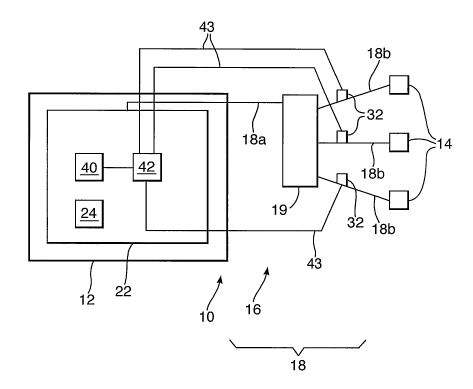
Figure 1 shows an optical network 10 in which a central station 12 is
connected to a
plurality of remote stations 14 by an optical fibre system 16. The fibre
system is arranged
in an hierarchical fashion, such that for the first hierarchical stage 18,
there is provided a
main optical fibre 18a and a plurality of branch optical fibres 18b, the
branch fibres 18b
being connected to the main fibre 18a at a splitter assembly or other
junction.19. Signals
travelling along the main line 18a in the downstream direction, that is, away
from the
central station 12, are split at the splitter assembly 19 such that a portion
of the signal
intensity then continues along each of the fibres 18b. Likewise, signals
travelling along
the branch fibres 18b in the upstream direction, towards the central station
12, are
combined or summed at the splitter 19, such that the signals from each branch
fibre
arriving at the same time at the splitter assembly travel along the main fibre
together. The
splitter assembly 19, for example a fibre coupler, will normally be arranged
to passively
split and combine downstream and upstream signals respectively, in which case
the
optical network 10 is known as a Passive Optical Network, or PON. Further
hierarchical
stages (not shown here for clarity) will normally be provided, such that the
branch lines
18b are each connected to respective further splitter assemblies for
connecting each
CA 02589792 2007-05-31
WO 2006/064243 PCT/GB2005/004850
6
branch line to a respective plurality of further branch lines. In this way,
the branch line
from one stage will act as the main line to the next stage.
In order to detect faults in the optical fibre system 16, or to otherwise
assess the state of
the system, monitoring apparatus 22 is provided at the central station 12. The
monitoring
apparatus 22 is configured to transmit test pulses onto the fibre system 16,
in particular
onto the main fibre 18a originating from the central station 12. Each pulse is
split at the
splitter assembly 19 such that for each pulse, a reduced intensity version of
that pulse
continues over each of the branch fibres 18b. As a pulse travels along a
fibre, in
particular a branch fibre 18b, the pulse will be backscattered in a
distributed fashion,
normally by a process of Rayleigh backscattering. Thus, each pulse will give
rise to a
return signal that is distributed over time, the duration of the. return
signal being
commensurate with the transit time of the pulse along a fibre (neglecting the
eventual
extinction of the pulse and/or the return signal due to attenuation). The
backscattered
(returned) signal from each branch fibre 18b. will travel in the upstream
direction and
combine at the splitter 19, returning along the main fibre 18a as a composite
signal
containing backscattered contributions from each of the branch fibres 18b (as
well as the
main fibre 18a).
The monitoring apparatus 22 includes a display 24 for showing as a trace the
return signal
level as a function of time. A possible trace 26 is shown in Figure 2. The
trace 26 shows
a plurality of features superposed on a background signal level which
decreases with
increasing time (time being measured from the launch of the test pulse into
the main line
18a). A step-like feature 28 in the trace 26 can be used to infer a loss in
the system,
whereas a spike feature 30 in the trace may indicate a reflecting or at least
partially
reflecting boundary, such as that caused by a fault or a fibre termination, or
a further
splitter assembly. Since each time position on the trace corresponds to a
distance along
the fibre path, the distance of a fault or other feature can be estimated from
the trace.
In order to facilitate the identification of the branch fibre responsible for
an observed
feature, a respective modulation device 32 is coupled to each of the branch
fibres 18b.
The monitoring apparatus 22 includes selection means such as a manual or
computer-
implemented switch 40 for selecting a modulation device 32. In order to
activate the
selected device, there is provided activation means 42 coupled to the switch
40. In the
case where the modulation devices are electrically powered, the activation
means is
CA 02589792 2007-05-31
WO 2006/064243 PCT/GB2005/004850
7
configured to transmit power to the or each selected modulation device 32 via
a
respective electrical line 43 in order to cause the or each modulation device
to modulate
optical signals. In the present example, where the modulation devices each
modulate
signals in the same way, the modulation devices will be selected one at a
time, or
equivalently, a branch line 18b will be selected one at a time, to make it
easier to
distinguish signals returned from the selected branch line. However, if the
modulation
devices 32 are configured such that each branch line or fibre is modulated in
a different
way, then more than one branch line may be selected together.
The return signal from the modulated branch or a selected modulated branch can
then be
chosen to be displayed as a trace in the manner of Figure 2, such that
features displayed
on the trace can be associated with the selected branch, signals from non-
selected
branches not being present on the trace. In this way, the monitoring apparatus
can
function as an Optical Time Domain Reflectometer (OTDR), in particular an OTDR
in
which features in a trace or a trace itself can be associated with a
particular branch line.
A more detailed view of the monitoring apparatus 22, together with part of an
optical
network 10 is shown in Figure 3 (only one remote station and branch line has
been shown
for clarity). The monitoring apparatus 22 includes an optical pulse source 118
with a short
coherence time (random phase changes in the output providing an irregular
component to
the signal). Pulses from the optical source 118 having the form of wave train
portions are
fed to an interferometer stage 120, here a Mach Zehnder interferometer with a
first path
124 and a second path 126, the paths ' 124, 126 being coupled at each end by a
respective first and second coupling stage 128, 130. For light travelling in
the
downstream direction, the first coupling stage 128 acts as a directional power
(intensity)
splitter, channelling light from the optical source 118 to each of the paths
124, 126, the
power to each path being shared in a predetermined manner (here, the first
coupling
stage acts as a 50:50 power splitter, the power input to each path being
equal, although a
different ratio could be used).,
Thus for each pulse provided by the optical source 118, that pulse is copied
such that
there is a first copy and a second copy, the first and second copies being in
this example
duplicates of one another. One copy travels along the first path 124 whilst
the other copy
travels along the second path 126. The second coupling stage 130 is coupled to
an
output 135 of the interferometer, which output is connected to the main fibre
18a. For light
CA 02589792 2007-05-31
WO 2006/064243 PCT/GB2005/004850
8
travelling in the downstream direction, the coupling stage 130 acts as a
combiner,
combining the light from the first and second paths and channelling this
combined light to
the interferometer output 135. The first path of the interferometer has a
delay stage 134
for increasing the transit time of light travelling therealong between the
first and second
coupling stages 128, 130, such that the transit time for light travelling
between the
coupling stages 128,130 is greater along the first path 124 than it is along
the second path
126. Thus, for each pulse produced by the optical source, the interferometer
120 serves
to delay one of the pulse copies relative to the other pulse copy by a delay
time D, pulse
copies being transmitted onto the optical fibre network 16 at different times
to one
another.
The additional (differential) delay D imposed by the delay stage 134 is
greater (preferably
much greater) than the coherence time of the optical source 118. Thus, when
downstream light travelling along the first and second paths is recombined by
the second
coupling stage 130, the interference between the light travelling along the
two paths
averages out, such that on average (over a timescale much greater than the
coherence
time) the amplitude of light upon recombination at the second coupling stage
130 is
constant for each pulse, (at least on a timescale of the pulse wavelength),
and insensitive
to the precise value of the differential path length.
For signals travelling in the return direction, that is, for return signals
arriving at the
interferometer 20 from the outstation 14, the second coupling stage 130 act as
a power
splitter, in a similar fashion to the action of the first coupling stage 128
on light in the
forward direction (from the optical source 118). In this way, return signals
are copied at
the second coupling stage 130, one copy being channelled along the first path
124, whilst
the other copy is channelled along the second path 126. The first coupling
stage 128 then
serves to combine light from the first and second paths in the return
direction, channelling
the combined light as an interference signal to a signal processing system 129
coupled to
an output of the first coupling stage 128.
The light source 118 may be a Light Emitting Diode, a Fabry-Perot Laser Diode,
or a
source of amplified spontaneous emission such as an Erbium-Doped Fibre
Amplifier or a
Semiconductor Optical Amplifier, but preferably the light source will be a
Super
Luminescent Diode, since this has a broad and smooth power spectrum, and a
short
coherence time of about 0.5 ps or less. The radiation produced by the optical
source will
CA 02589792 2007-05-31
WO 2006/064243 PCT/GB2005/004850
9
preferably be unpolarised, or alternatively a de-polarising unit 143 may be
provided
between the light source and the interferometer, for depolarising the light
before the light
is injected into the interferometer (the de-polarising unit may be for
example, a Fibre Lyot
de-polariser). A polarisation controller or de-polariser 149 may be provided
in one of the
paths of the interferometer, here, the first path, so that the polarisation of
light from the
first path combining in the return direction at the first coupler 128 is at
least partially
aligned with that of the light from the other path. However, a depolariser
such as a Lyot
depolariser may be used. This has the advantage of effectively scrambling any
polarisation structure in the returning backscatter signal making it much
easier to detect
loss defects. Typically, the source will operate at a wavelength of between 1
micron and 2
microns, preferably around 1.3 or 1.55 microns, in order to efficiently make
use of
standard telecommunications optical fibre, such fibre being configured to
support single
mode transmission at this wavelength. Typically, the fibre will have a single
core of a
diameter which is around 9 or 10 microns.
The operation of the monitoring apparatus 22 can best be understood by
considering
return components of a downstream pulse copies returned from a particular
point on a
(branch) fibre: this corresponds to the signal level of the trace 26 at a
particular time, such
as time tl.
For each pulse generated by the source 118, there will be four resulting
signals: a non-
retarded signal SO which has travelled along the second path 126 of the
interferometer
120 in both the forward and reverse directions; a first retarded signal S1
delayed by a
delay D in the forward direction (but not the reverse direction); a second
retarded signal
S2 retarded by the delay D in the reverse direction (but nor the forward
direction); and, a
twice-retarded signal S3 retarded by a delay 2D, signal S3 being retarded in
each of the
forward and reverse directions.
The first and second retarded signals S1, S2, which are retarded in one
direction only will
be returned to the first coupling stage 128 at the same time. In the absence
of any
disturbance or modulation in the fibre 18a, these signals are copies of one
another (i.e.
have the same phase or phase changes) and the signals will interfere or
otherwise
combine constructively at the first coupling stage 128. However, if the phase
of one of the
pair of the signals S1, S2 is changed along the fibre relative to the phase of
the other, the
signals S1, S2 will no longer interfere constructively. Thus, if a phase
modulation signal is
CA 02589792 2007-05-31
WO 2006/064243 PCT/GB2005/004850
imposed on one or both of the signals S1, S2, this signal or a signal
corresponding to the
modulation signal will be reproduced in a particularly sensitive manner when
the signals
S1, S2 are recombined at the interferometer, the phase modulation being
reproduced as
an amplitude modulation at an output of the first coupling stage.
5
Each modulation device is configured, when activated, to impose a sinusoidal
modulation
on the phase of signals in a respective branch fibre. A sinusoidal modulation
is
particularly desirable because signals can be modulated in both the upstream
and the
downstream direction, since the superposition of two sine waves will also be a
sine wave.
Because the interferometer arrangement is sensitive to a phase disturbance,
the
sinusoidal phase modulation results in a corresponding amplitude modulation at
the first
coupling stage of the interferometer at the same frequency as that of the
applied phase
modulation. Thus, an ultrasound or other modulation signal will serve to shift
or translate
the trace signal (returned through backscattering) to a frequency at the
modulation
frequency, which will be a radio frequency if the modulation signal is an
ultra sound signal.
The signal processing stage 129 (coupled to the first coupling stage 128) is
configured to
distinguish the modulated signals from unmodulated signals. As part of the
signal
processing stage 129, a photo detector 51 is optically coupled to the, output
of the first
coupling stage 128 so as to convert optical signals from the first coupling
stage into
electrical signals. The electrical signals are fed to a band pass amplifier
52, the band
pass amplifier acting in part as a band pass filter tuned such that signals
that the
modulation frequency of the selected branch fibre are selectively amplified.
Amplified
signals from the amplifier are passed to a signal processing unit 54. The,
signal
processing unit 54 is configured to output the amplified signals to the
display 24, together
with a time sweep signal, such that the display 24 can show the amplified
output signal
from the band pass amplifier as a function of time.
In the example shown in figure 3, the central station includes 'an Optical
Line Terminal
(OLT) for controlling traffic to and from a plurality of Optical Network Units
(ONU) at each
respective outstation (only one of which is shown in figure 3).
The OLT is connected to the near end of the main line 18a, whilst each ONU is
connected
to a respective-branch line. In order for the monitoring apparatus to be
connected to the
CA 02589792 2007-05-31
WO 2006/064243 PCT/GB2005/004850
11
optical network extending between the OLT and each ONU, in particular whilst
the
network is carrying traffic, a wavelength sensitive coupler 60 is provided in
the main line
for coupling the main line to the monitoring apparatus 22. Likewise,
respective
wavelength sensitive couplers 62 are provided towards the ends of the branch
lines for
coupling each branch line to a respective ONU. This will allow test signals to
be
transmitted on the optical network 16 at one carrier wavelength whilst the
optical network
is being used to transfer data on a different carrier wavelength, the optical
network 16
carrying the two wavelengths in a wavelength division multiplexed manner.
In figure 4, a portion of a network is shown in which each of M branches 18b
is split by a
respective splitter assembly 19 into a plurality of N sub-branches 18c, where
M and N are
integers greater than 1(for clarity, only one such set of sub-branches is
shown). A
modulator device 32 is provided for each of the sub-branch lines 18c, as well
as for each
of the main branch line 18b.
To locate or discover a fault or feature on a branch line, the modulator
devices are
preferably operated one at a time, in a sequential manner, until the fault or
feature has
been found.
The position of a modulation device on a branch line will determine the extent
of the
branch line that can be evaluated or sensed. Signals that are returned at
points upstream
of the modulation point will not be modulated and will therefore not be
amplified by the
band pass amplifier 52.
Each modulation device is positioned in an upstream portion of its associated
branch line
that is towards the upstream splitter assembly from which that branch line
originates.
Such a positioning will increase the extent of the branch line that can be
sensed, since
only those signals that have propagated beyond the modulation device in the
downstream
direction will be modulated and hence displayed on the display 24. Signals
that have
been returned from signals upstream of the modulation device will be
effectively removed
by the band pass amplifier 53, whose effect is to selectively remove
frequencies that are
not in a band pass encompassing the modulation frequency of the modulation
device.
Considering the situation in which the modulation on an inner branch 18b is
activated
whilst the remaining modulation devices are not activated, the modulated
signals returned
CA 02589792 2007-05-31
WO 2006/064243 PCT/GB2005/004850
12
at the monitoring apparatus will initially be signals returned from points
along the inner
branch. Signals arriving at a later time (which later time corresponds to the
forward and
return transit time along the inner branch) will be returned at points along
each of the N
outer branches 18c which are connected to the inner branch. In order to
distinguish
signals that have been returned from the different outer branches 18c, the
modulation
device on the inner branch 18b will be placed in an off state, in which the
modulation
device is not modulating. The modulation devices of the outer branches
connected to the
inner branch will be placed in the on state one at a time. Thus, only those
signals
returning from the modulated outer branch will be amplified by the band pass
amplifier 52,
allowing each outer branch to be assessed individually.
Figure 5 shows an example of a modulation device, here a semiconductor electro-
optical
modulator 32. The modulator includes a light conducting channel 321 which
extends
between a first and a second coupling means 322, 323, for coupling the channel
to an
upstream and a downstream portion of an optical fibre 18b. Either side of the
channel
321 are provided first and second electrically conducting regions 324 for
providing an
electric field across the channel 321. The conducting regions are electrically
connected to
an electrical drive circuit 325 for applying an alternating voltage to the
conducting regions
324. The drive circuit is powered from an electrical power line 43, the
transmission of
power to the drive circuit 325 acting as an activation signal. Alternatively,
an activation
signal could be an additional signal, in response to which the drive circuit
is configured to
draw power from the power line. In such a situation, the activation signal
would preferably
be a wireless signal, which wireless signal may be received by a wireless
receiver 326
connected to the driving circuit.
The optical pulses produced by the source will each have a duration of about 1
microsecond (corresponding to a frequency bandwidth of about 1 MHz), the
coherence.
time of the pulses if a Fabry Perrot laser is used being in the region of 1
nanosecond.
They modulation frequency using an electro-optic modulator (or other
modulator) will be
about 3 or 4 MHz. The repetition rate of the pulses will depend on the length
of fibre path
being assessed - for a range of 100 km, a repetition rate of about 1
millisecond may be
used (that is, a pair of pulse copies will be launched every 1 millisecond).
In another embodiment, an external modulation device may be used, such as an
acoustic
modulation device shown in Figure 6. The modulator device comprises a piezo
electric
CA 02589792 2007-05-31
WO 2006/064243 PCT/GB2005/004850
13
plate transducer 21 bonded to a block of metal or other electrically
conductive material 22
which acts as a mount. The plate transducer has upper and lower electrode
layers 22, 23,
and a region of piezo electric material 27 (such as lithium niobate or quartz)
therebetween. However, the plate 21 may initially have a lower electrode layer
only. The
plate may then be bonded to the block 22 and polished down to the required
thickness for
resonance on the mount. Subsequently, the upper electrode can be applied. In
either
case the mount 22 itself forms the ground connection to the lower electrode of
the piezo
electric plate. The upper and lower electrodes are connected to an electrical
drive circuit
(not shown) for applying an electrical signal to the electrodes. An optical
fibre (one of the
branch fibres 18b) is mounted on the upper electrode 23 such that the fibre is
acoustically
coupled to the piezo electric material 21 of the piezo electric plate. A
grease material 25
may be provided for improving the acoustic coupling between the fibre 18a and
the plate
transducer (for permanent coupling, an epoxy resin may be used instead). A
hinged clamp
arrangement 30 may be used to releasably retain the fibre 18b in an
acoustically coupled
relationship with the piezo electric plate. The hinged clamp arrangement 30
includes an L
shaped arm member 38 pivotally connected at one end to the mounting block 22
by a
hinge 34. At the other end of the arm member a receiving member 36 having some
resilience is provided to bear against an upper portion of fibre 18b. A screw
clamp (not
shown) is provided between the arm member and the mounting block for biasing
the arm
member, in particular the receiving member, against the fibre. The fiber may
but need not
be bared. Conveniently, the modulator of Figure 6 may be coupled to an
existing branch
fibre without cutting through or otherwise interrupting the fibre.
In the case of acoustic modulation, the acoustic waves introduced into the
fibre cause a
change in the refractive index of the light carrying medium (glass) of the
fibre, with the
result that a corresponding phase modulation is imposed on the light
travelling through the
fibre (some amplitude modulation may also occur).
In one embodiment where acoustic modulation is performed, instead of applying
an
ultrasound signal, a signal of lower frequency may be introduced. In
particular, a tone
frequency that is within the bandwidth of the unmodulated return signal may be
applied.
In further detail, an acoustic tone at a frequency F = f(rep)/2 (where, f(rep)
is the OTDR
pulse repetition frequency or rate) is applied to the PON branch to be tested.
In practice it
might be helpful for the signal processing to use a frequency that is sub-
harmonically
CA 02589792 2007-05-31
WO 2006/064243 PCT/GB2005/004850
14
related to f(rep) such as F = f(rep)/n (where n is an integer greater than 1).
The
backscatter return (trace) signal from this branch will now carry the acoustic
tone. Thus,
this branch can now be selected from the un-modulated signals from all other
branches by
filtering the pre-averaged signal from each spatial location with a narrowband
filter centred
on frequency F. A narrow filter is used in order to maximise the systems
sensitivity and
selectivity to the chosen tone frequency F. The filtered signals from each
spatial location
will be a tone at frequency F whose magnitude corresponds to the backscatter
signal level
from that spatial location. The tone is therefore detected and signal averaged
in order to
achieve the desired signal to noise ratio for the measurement being
undertaken. The
amount of averaging will depend on the filter bandwidth, the distance to the
spatial
location(s) of interest and on the size of the features being uncovered.
Although a filter at
frequency F may be used for each range resolution cell in the OTDR response,
in
practice, this multi-channel filter would be implemented using well known
digital signal
processing techniques.
The use of an in-band frequency for F has the advantage that this will be
simpler to
generate, will require less power, and should be of lower cost than the
ultrasonic method
described above. Furthermore, F may be less than 1 kHz, which will be easier
to
acoustically modulate than frequencies in the region of 5 MHz that can be used
for the
ultrasonic modulation.
The following additional comments are provided.
Fault locating on PONs is a major problem for the network operator and could
seriously
limit their use as an Access Technology. This in turn could jeopardise the
potential cost
savings that such systems are expected to offer. The problem stems from the
ambiguity
that OTDRs encounter due to the multiple backscatter returns from the PON
legs. Whilst
the primary use of the embodiments above is fault location in a PON, the
technology could
be used to allow unidirectional low speed data transmission to be injected
anywhere along
an optical fibre cable using an acoustic modulator without the need for an
optical coupler
or breaking into the cable.
Some of the embodiments provide a way of allowing an OTDR to discriminate
between
the legs of a PON. They use a combination of the interferometer OTDR and an
ultrasonic
or lower frequency activator, placed on each leg of a PON, which allows, the
backscatter
CA 02589792 2007-05-31
WO 2006/064243 PCT/GB2005/004850
signal from the selected leg to be discriminated at the receiver. The design
is suitable for
measuring the distributed 'loss and for fault location. The invention could be
used to be
used to allow unidirectional low speed data transmission to be injected
anywhere along an
optical fibre cable using an acoustic modulator without the need for an
optical coupler or
5 breaking into the cable.
One important purpose of this invention is to recover the position dependence
of the
backscatter signal from the selected leg rather than to solely operate it as a
disturbance
sensor. However it can be envisaged that it would be useful to include a
disturbance
10 sensor functionality. If interferometric OTDR functionality only is
required it will be
desirable to minimise the disturbance sensitivity of the system. This can be
achieved, to
good advantage, by minimising the differential delay 'D' in the un-balanced
Mach-
Zehender interferometer to the point where the frequency shifted backscatter
signal is
passed with low loss (where ultrasonic modulation is used), but the much lower
frequency
15 disturbance signals are attenuated. Reducing 'D' also reduces the physical
size and the
insertion loss of the interferometer. If the disturbance sensor functionality
is also required
a different delay line used only by the disturbance sensor could be
incorporated into the
design possibly using a different wavelength. It may also be possible to
utilise the same
delay line for both the interferometric OTDR and the disturbance sensor.