Note: Descriptions are shown in the official language in which they were submitted.
CA 02590088 2010-05-06
70488-342
1
OUTBOARD ENGINE SYSTEM
BACKGROUND OF THE INVENTION
FIELD OF THE INVENTION
The present invention relates to an outboard engine system
comprising: a casing coupled to a swivel case via a swivel shaft; an engine
mounted in an upper part of the casing such that a crankshaft of the engine is
vertically arranged and a cylinder block of the engine faces in a direction
opposite
to the swivel shaft; a torque converter; a vertically arranged output shaft
connected to the crankshaft through the torque converter; a horizontally
arranged
propeller shaft provided below the output shaft; and a forward-reverse
shifting
gear mechanism for providing a connection between the output shaft and the
propeller shaft; the torque converter, the output shaft, the propeller shaft
and the
forward-reverse shifting gear mechanism being disposed in the casing.
DESCRIPTION OF THE RELATED ART
Such an outboard engine systems is already known as disclosed in
U.S. Patent No. 3,407,600.
In the outboard engine system disclosed in U.S. Patent
No. 3,407,600, a lower surface of a torque converter is supported
CA 02590088 2007-05-24
- 2 -
via a bearing by a bracket which is connected to a casing,
and thus the overall weight of the torque converter is borne
by the bearing. Therefore, the outboard engine system
requires an expensive bearing having a large load capacity,
leading to a difficulty in reducing the cost.
SUMMARY OF THE INVENTION
The present invention has been achieved in view of the
above problem, and has an object to provide an outboard
engine system which enables support of a torque converter
without using any bearing exclusively for supporting the
overall weight of the torque converter, thereby reducing the
cost.
In order to achieve the above object, according to a
first feature of the present invention, there is provided an
outboard engine system comprising: a casing coupled to a
swivel case via a swivel shaft; an engine mounted in an upper
part of the casing such that a crankshaft of the engine is
vertically arranged and a cylinder block of the engine faces
in a direction opposite to the swivel shaft; a torque
converter; a vertically arranged output shaft connected to
the crankshaft through the torque converter; a horizontally
arranged propeller shaft provided below the output shaft; and
a forward-reverse shifting gear mechanism for providing a
connection between the output shaft and the propeller shaft;
the torque converter, the output shaft, the propeller shaft
and the forward-reverse shifting gear mechanism being
disposed in the casing, wherein the torque converter
includes: a pump impeller; a turbine runner arranged above
CA 02590088 2007-05-24
3 -
the pump impeller and connected to the output shaft; a stator
arranged between the pump impeller and the turbine runner;
and a transmission cover integrally connected to an outer
periphery of the pump impeller so as to cover an upper
surface of the turbine runner; wherein a drive plate is
secured at its central portion to a lower end of the
crankshaft by a first bolt, and an outer peripheral portion
of the drive plate is secured to the transmission cover by a
second bolt; and wherein the torque converter is suspended
from the crankshaft via the drive plate.
According to a second feature of the present invention,
in addition to the first feature, the output shaft is divided
into an upper output shaft spline-fitted to a hub of the
turbine runner, and a lower output shaft spline-fitted to a
lower end of the upper output shaft and connected to the
forward-reverse shifting gear mechanism; and a bearing for
supporting a downward load of the upper output shaft is
attached to a support member integrally connected to the
casing.
According to a third feature of the present invention, in
addition to the first or second feature, a thrust needle
bearing is provided between a hub of the pump impeller and a
hub of the stator.
According to a fourth feature of the present invention,
in addition to the first or second feature, a dish-shaped
recess is formed in a central portion of the transmission
cover so as to receive a head portion of the first bolt.
According to a fifth feature of the present invention,
there is provided an outboard engine system comprising: a
CA 02590088 2007-05-24
4 -
casing coupled to a swivel case via a swivel shaft; an engine
mounted in an upper part of the casing such that a crankshaft
of the engine is vertically arranged and a cylinder block of
the engine faces in a direction opposite to the swivel shaft;
a torque converter; a vertically arranged output shaft
connected to the crankshaft through the torque converter; and
a horizontally arranged propeller shaft provided below the
output shaft; and a forward-reverse shifting gear mechanism
for providing a connection between the output shaft and the
propeller shaft; the torque converter, the output shaft, the
propeller shaft and the forward-reverse shifting gear
mechanism being disposed in the casing; wherein the torque
converter includes: a pump impeller; a turbine runner
arranged to be opposed to the pump impeller and connected to
the output shaft; a stator arranged between the pump impeller
and the turbine runner; and a transmission cover arranged to
cover an rear surface of the turbine runner and providing a
connection between the crankshaft and the pump impeller; and
wherein an annular bag-shaped foreign material trap opening
upward is formed in the pump impeller and an inner peripheral
surface of a largest diameter portion of the transmission
cover so that the trap can capture a foreign material
separated from a working oil in the torque converter by
centrifugation.
According to a sixth feature of the present invention, in
addition to the fifth feature, the pump impeller and the
transmission cover are coupled to each other by fitting to
each other a male mating surface formed on an outer periphery
of an enlarged diameter portion extending from an outer
CA 02590088 2007-05-24
- 5 -
peripheral end of the pump impeller and a female mating
surface formed on an inner 'periphery of a peripheral wall
portion of the transmission cover, and then welding together
the enlarged diameter portion and the peripheral wall portion,
thereby forming an annular recess formed in an inner
peripheral surface of the peripheral wall portion so as to be
adjacent to the female mating surface; and an extension wall
is formed on the enlarged diameter portion so as to cover the
annular recess from the inner peripheral side, thereby
defining the foreign material trap.
According to a seventh feature of the present invention,
in addition to the sixth feature, the extension wall is
formed to be thin and rise from an inner peripheral edge of
the enlarged diameter portion.
According to an eighth feature of the present invention,
in addition to the sixth feature, the enlarged diameter
portion has a radially inwardly reduced diameter portion
which constitutes an inner peripheral wall of the foreign
material trap; and the peripheral wall portion has a radially
outwardly increased diameter portion which constitutes an
outer peripheral wall of the foreign material trap.
According to a ninth feature of the present invention,
there is provided an outboard engine system comprising: a
casing coupled to a swivel case via a swivel shaft; an engine
mounted in an upper part of the casing such that a crankshaft
of the engine is vertically arranged and a cylinder block of
the engine faces in a direction opposite to the swivel shaft;
a torque converter; a vertically arranged output shaft
connected to the crankshaft through the torque converter; and
CA 02590088 2007-05-24
- 6 -
a horizontally arranged propeller shaft provided below the
output shaft; and a forward-reverse shifting gear mechanism
for providing a connection between the output shaft and the
propeller shaft; the torque converter, the output shaft, the
propeller shaft and the forward-reverse shifting gear
mechanism being disposed in the casing; wherein the torque
converter includes: a pump impeller; a turbine runner
arranged above the pump impeller so as to define a
circulation circuit of a working oil between the turbine
runner and the pump impeller, and connected to the output
shaft; and a transmission cover arranged to cover an upper
surface of the turbine runner and providing a connection
between the crankshaft and the pump impeller; and wherein a
clutch chamber which has a diameter larger than that of the
circulation circuit is formed between the transmission cover
and the turbine runner, and a lock-up clutch which has a
diameter larger than that of the circulation circuit and
which is capable of providing a direct connection between the
transmission cover and the turbine runner is disposed in the
clutch chamber.
According to a tenth feature of the present invention, in
addition to the ninth feature, a cylindrical peripheral wall
portion is integrally formed in the transmission cover so as
to surround the turbine runner, an enlarged diameter wall is
integrally formed in a shell of the pump impeller so as to
radially extend from an outer peripheral end of the shell,
and the peripheral wall portion and the enlarged diameter
wall are coupled to each other to define an outer peripheral
CA 02590088 2007-05-24
7 _
portion of the clutch chamber in which a frictional
engagement portion of the lock-up clutch is disposed.
The support member and the frictional engagement portion
correspond to a bearing bracket 14 and a friction lining 83
of a clutch piston 82, respectively, of an embodiment of the
present invention which will be described later.
With the first feature of the present invention, because
the torque converter is suspended from the crankshaft via the
drive plate such that a lower end portion of the torque
converter becomes free, the overall weight of the torque
converter is borne by the crankshaft which is firmly
supported by the crank case of the engine. Therefore, it is
not necessary to use a dedicated bearing for supporting the
overall weight of the torque converter, thereby reducing the
cost. Also, even when the torque converter thermally expands
in its axial direction, it is possible to prevent an
excessive thrust load from acting on the torque converter and
the crankshaft. Further, because the drive plate has an
appropriate elasticity, elastic deformation of the drive
plate alleviates shocks to the torque converter due to up-
and-motion of a ship, thereby contributing to an improvement
of durability.
With the second feature of the present invention, it is
possible to prevent the weight of the output shaft from
acting on the torque converter, drive plate and crankshaft,
and also prevent the axial thermal expansion of the torque
converter from affecting the output shaft. Further, the
output shaft is divided into the upper output shaft which is
spline-fitted to the hub of the turbine runner, and the lower
CA 02590088 2007-05-24
8 -
output shaft which is spline-fitted to the lower end portion
of the upper output shaft and is coupled to a forward-reverse
shifting gear mechanism; and the downward load of the upper
output shaft is supported by the bearing which is attached to
a support member connected to the casing. Therefore, the
axial thermal expansions of the torque converter, upper
output shaft and lower output shaft are respectively absorbed
by their spline-fitted portions, thereby preventing
generation of overstress. Because the bearing supports only
the downward load including the weight of the upper output
shaft, the load is relatively small, thereby improving the
durability of the bearing.
With the third feature of the present invention, the
weights of the turbine runner and the stator are reasonably
borne by the pump impeller via the thrust needle bearing,
thereby improving the durability of the torque converter.
With the fourth feature of the present invention, because
the head of the first bolt is received in the dish-shaped
recess formed in the transmission cover, the drive plate and
the transmission cover can be arranged close to each other
without interference by the head of the first blot, thereby
downsizing the power unit including the engine and the torque
converter.
With the fifth feature of the present invention, the
foreign materials having flowed into the torque converter are
separated from the working oil by centrifugation and
efficiently captured in the annular foreign material trap by
a remarkably simple structure of the annular bag-shaped
foreign material trap opening upward which is formed in the
CA 02590088 2007-05-24
9 -
pump impeller and the inner peripheral surface of the largest
diameter portion of the transmission cover. Further, because
the torque converter is arranged vertically with its axis
extending in the vertical direction, and the foreign material
trap is formed into a bag-shape, the foreign materials once
received in the foreign material trap are reliably kept to be
captured therein, thereby preventing any clogging of an oil
filter and a control valve due to the foreign materials.
With the sixth feature of the present invention, the
foreign material trap can be easily formed by utilizing the
coupled portions between the pump impeller and the
transmission cover.
With the seventh feature of the present invention, the
capacity of the foreign material trap can be increased
without particularly increasing the outer diameter of the
torque converter.
With the eighth feature of the present invention, the
reduced diameter portion and the increased diameter portion
serve as reinforcing ribs to increase the strength of the
shell and the transmission cover, thereby improving their
durability against the centrifugal force.
With the ninth feature of the present invention, a large
torque is efficiently transmitted from the crankshaft to the
output shaft via the lock-up clutch, by bringing into a
connected state the lock-up clutch having a diameter larger
than that of the circulation circuit of the torque converter,
without particularly enlarging the pump impeller and the
turbine runner. Further, because the lock-up clutch having a
diameter larger than that of the circulation circuit of the
CA 02590088 2007-05-24
- 10 -
torque converter is arranged above the pump impeller and the
turbine runner, the pump impeller and the turbine runner can
be arranged close to the swivel case by arranging the lock-up
clutch above the swivel case, thereby downsizing the outboard
engine system.
With the tenth feature of the present invention, the
clutch chamber having a diameter larger than that of the
circulation circuit can be easily formed by coupling together
the peripheral wall portion of the transmission cover and the
enlarged diameter wall of the shell of the pump impeller.
Further, the frictional engagement portion of the lock-up
clutch having a diameter larger than that of the circulation
circuit can be easily disposed in the outer peripheral
portion of the clutch chamber.
Furthermore, the enlarged diameter wall radially
extending from the outer peripheral end of the shell of the
pump impeller functions to reinforce the outer peripheral
portion of the pump impeller, thereby contributing to an
improvement of the durability of the pump impeller.
The above-mentioned object, other objects,
characteristics, and advantages of the present invention will
become apparent from a preferred embodiment, which will be
described in detail below by reference to the attached
drawings.
BRIEF DESCRIPTION OF THE DRAWINGS
FIG. 1 is a side view showing an outboard engine system
according to an embodiment of the present invention.
CA 02590088 2007-05-24
- 11 -
FIG. 2 is an enlarged sectional view showing the portion
2 of FIG. 1.
FIG. 3 is an enlarged view showing a torque converter in
FIG. 2.
FIG. 4 is a view showing a hydraulic circuit including an
oil pump.
FIG. 5 is an enlarged sectional view showing the portion
(foreign material trap) in FIG. 3.
FIG. 6 is a view corresponding to FIG. 5, but showing a
modification of the foreign material trap.
FIG. 7 is a view corresponding to FIG. 5, but showing
another modification of the foreign material trap.
DESCRIPTION OF THE PREFERRED EMBODIMENT
A first embodiment of the present invention will be
described with reference to FIGS. 1 to 6. In FIG. 1, an
outboard engine system 0 includes a casing 1 which has a
water-cooled multi-cylinder four-stroke engine E mounted in
its upper portion, and supports a propeller shaft 3 at its
lower portion. The propeller shaft 3 has a propeller 2
provided at its rear end. A vertically-extending swivel shaft
6 is mounted to the casing 1 via an upper arm 4 and a lower
arm 5 so as to situate in front of the casing 1. The swivel
shaft 6 is rotatably supported by a swivel case 7 which is
coupled to a stern bracket 8 via a horizontally-extending
tilt shaft 9. The stern bracket 8 is cramped to a transom Bt
of a body of a ship. Therefore, the casing 1 is horizontally
rotatable around the swivel shaft 6, and vertically tiltable
CA 02590088 2007-05-24
- 12 -
around the tilt shaft 9. The reference numeral Ef denotes a
removable engine hood for covering the engine E.
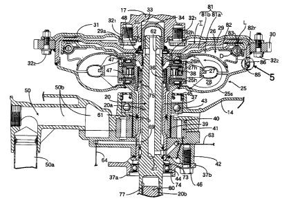
In FIG. 1 and FIG. 2, the above casing 1 includes the
extension case 10, the mount case 11 bolt-coupled to an upper
end of the extension case 10, and a gear case 12 bolt-coupled
to a lower end of the extension case 10. The extension case
includes an upper case 10a and a lower case 10b bolt-
coupled to the upper case 10a. The mount case 11 is jointed
to an upper end surface of the upper case 10a by a plurality
of bolts 163.
The casing 1 further includes annular lower distance
members 13, an bearing bracket 14, and annular upper distance
members 15, which are sequentially superimposed on the upper
end of the mount case 11. The engine E is mounted to the
upper distance member 15 with the crankshaft 17 being
vertically or perpendicularly arranged and the cylinder block
18 facing rearward. The bearing bracket 14 and upper distance
member 15 are secured to the cylinder block 18 and a bottom
wall of the crankcase 19 of the engine E by a plurality of
bolts 161. The lower distance member 13, the bearing bracket
14, and the upper distance member 15 are secured to one
another by a plurality of bolts 162.
The torque converter T is vertically arranged in the
annular upper distance member 15, and the output shaft 20
coupled to the crankshaft 17 via the torque converter T is
vertically arranged in the extension case 10.
The gear case 12 horizontally supports the propeller
shaft 3 having the propeller 2 at its rear end, and houses a
CA 02590088 2007-05-24
13 -
forward-reverse shifting gear mechanism 21 connecting the
propeller shaft 3 to the output shaft 20.
In operation of the engine E, the power thereof is
transmitted from the crankshaft 17 to the output shaft 20 via
the torque converter T, and further to the propeller shaft 3
via the forward-reverse shifting gear mechanism 21, thereby
driving the propeller 2. The rotational direction of the
propeller 2 is controlled and switched by the forward-reverse
shifting gear mechanism 21.
In the extension case 10, an oil tank 22 (see FIG. 1 and
FIG. 4) open to the mount case 11 is integrally formed with
the upper case 10a of the extension case 10. The oil tank 22
stores oil 23 which is used in both lubrication of the engine
E and operation of the torque converter T.
As clearly shown in FIG. 3, the torque converter T
includes a pump impeller 25, a turbine runner 26 arranged
above the pump impeller 25 and opposed to the pump impeller
25, a stator 27 arranged between the inner peripheral
portions of the pump impeller 25 and the turbine runner 26,
and a circulation circuit 28 of working oil which is defined
between these three impellers 25 to 27. The three impellers
25 to 27 are arranged to have a common vertical axis, as in
the case of the crankshaft 17 and the output shaft 20.
The pump impeller 25 integrally includes a transmission
cover 29 for covering an upper surface of the turbine runner
3. A ring gear 30 for starting operation is secured to an
outer peripheral surface of the transmission cover 29. A
steel drive plate 31 is secured to the ring gear 30 by a
plurality of annularly-arranged second bolts 322. The drive
CA 02590088 2007-05-24
14
plate 31 is also secured to a lower end of the crankshaft 17
by plurality of annularly-arranged first bolts 321. The
torque converter T is suspended from the crankshaft 17 via
the drive plate 31. In this structure, a dish-shaped recess
29a is formed in a central portion of the transmission cover
29 so as to receive a head portion of the first bolts 321, and
the drive plate 31 is arranged close to the transmission
cover 29.
A cup-shaped supporting cylinder 34 is secured to a
central part of the transmission cover 29. The supporting
cylinder 34 is slidably fitted into a supporting hole 33
which is open to the central part of the lower end surface of
the crankshaft 17. The output shaft 20 has an upper end which
extends to the inside of the supporting cylinder 34 and is
supported in the supporting cylinder 34 via a bearing bush 35.
A hub 26h of the turbine runner 26 is spline-coupled to the
output shaft 20. A hollow stator shaft 37 is arranged around
the outer periphery of the output shaft 20 so as to be
supported by the output shaft 20 via a needle bearing 36. A
known free wheel 38 is interposed between the stator shaft 37
and a hub 27h of the stator 27.
A hollow pump shaft 39 is arranged at the outer periphery
of the stator shaft 37. The hollow pump shaft 39 is
integrally coupled to the pump impeller 25 and extends
downward. The pump shaft 39 is supported by the bearing
bracket 14 via an upper ball bearing 43 on the side of the
outer periphery. An oil pump 41 driven at the lower end
portion of the pump shaft 39 is attached to a pump housing 40
formed at a lower surface of the bearing bracket 14. A pump
CA 02590088 2007-05-24
- 15 -
cover 42 covering a lower surface of the oil pump 41 is bolt-
coupled to a lower surface of the bearing bracket 14. In this
structure, the pump shaft 39 is slidably fitted to an inner
lace of an upper ball bearing 43, and is also slidably
spline-fitted to a rotor of the oil pump 41. With this
arrangement, the lower end of the torque converter T can be
freely moved in the axial direction.
An oil seal 45 is attached to an upper end portion of the
bearing bracket 14 such that its lip is in close contact with
an outer peripheral surface of the pump shaft 39 at a
position immediately above the ball bearing 43.
The stator shaft 37 has a large diameter portion 37a at
its lower end. A flange 37b is integrally formed on an outer
periphery of the large diameter portion 37a. The flange 37b
is secured to the pump cover 42 by a bolt 46. A lower ball
bearing 44 is mounted to its inner periphery of the flange
37b so as to support the output shaft 20.
Therefore, the pump shaft 39 is supported by the bearing
bracket 14 via the upper ball bearing 43, and the output
shaft 20 is supported by the large diameter portion 37a of
the stator shaft 37 via the lower ball bearing 44, thereby
reasonably supporting the pump shaft 39, the stator shaft 37,
and the output shaft 20 and downsizing the vertical fluid
power transmission including the torque converter T and
output shaft 20.
Because the oil pump 41 is mounted to the bearing bracket
14 in a space between the upper and lower ball bearings 43
and 44, thereby downsizing the vertical fluid power
transmission having the oil pump 41.
CA 02590088 2007-05-24
- 16 -
Thrust needle bearings 47 and 47' are interposed between
the hubs 25h, 27h and 26h of the pump impeller 25, stator 27
and turbine runner 26. Also, a thrust needle bearing 48 is
interposed between the hub 26h of the turbine runner 26 and
the transmission cover 29.
In FIGS. 2 to 4, the oil pump 41 draws up oil stored in
the oil tank 22 through the oil suction passage 50, and
discharges the oil to a first oil supply passage 51. The oil
discharged to first oil supply passage 51 is filtered by an
oil filter 53 provided in the middle of the first oil supply
passage 51, and supplied to a lubricated portion of the
engine E. After the lubrication, the oil flows downward to
the bottom portion of the crankcase 19 of the engine E, and
returns to the oil tank 22 via a first oil return passage 54.
An oil relief passage 55 is a branch from the first oil
supply passage 51 upstream of the oil filter 53, and leads to
the oil suction passage 50. The oil relief passage 55 has a
pressure relief valve 56 which opens when an oil pressure of
the first oil supply passage 51 exceeds a specified value.
A second oil supply passage 52 is connected to the first
oil supply passage 51 so as to supply the working oil to the
torque converter T. A second oil return passage 59 is
connected to an intake side of the oil pump 41 so as to guide
the oil returning from the torque converter T.
As shown in FIG. 3, a clutch oil chamber 81 is defined
between the turbine runner 26 and the transmission cover 29.
The clutch oil chamber 81 communicates at its outer
peripheral portion with the circulation circuit 28. A
cylindrical peripheral wall portion 86 is integrally formed
CA 02590088 2007-05-24
- 17 -
in the transmission cover 29 so as to surround the turbine
runner 26. A enlarged diameter wall 85 is integrally formed
in the shell 25s of the pump impeller 25 so as to radially
extend from the outer peripheral end of the shell 25s. The
peripheral wall portion 86 and the enlarged diameter wall 85
are joined to each other to define a circular outer
peripheral portion of the clutch chamber 81 which has a
diameter larger than that of the circulation circuit 28. The
clutch chamber 81 is provided with a lock-up clutch L which
is capable of providing a direct connection between the
turbine runner 26 and the transmission cover 29.
The lock-up clutch L comprises a disc-shaped clutch
piston 82 having a diameter larger than that of the
circulation circuit 28. The clutch piston 82 is disposed in
the clutch oil chamber 81 so that the clutch oil chamber 81
is divided into an inside chamber 81a on the side of the
turbine runner 26, and an outside chamber 81b on the side of
the transmission cover 29. The clutch piston 82 has an
annular friction lining 83 having a diameter larger than that
of the circulation circuit 28 on its side surface which is
opposed to the inner wall of the transmission cover 29. The
clutch piston 82 also has a hub 82h slidably supported on the
outer peripheral surface of the hub 26h of the turbine runner
26 so that the hub 82h is movable between a connected
position where the friction lining 83 is pressure-pressed on
the inner wall of the transmission cover 29 and a non-
connected position where the friction lining 83 is separated
from the inner wall. In this way, the lock-up clutch L is
formed to have a diameter larger than that of the circulation
CA 02590088 2007-05-24
- 18 -
circuit 28. As shown in FIG. 2, the torque converter T is
arranged such that the pump impeller 25 and the turbine
runner 26 are positioned close to the swivel case 7 and such
that the lock-up clutch L is positioned above the swivel case
7.
An annular rim portion 82r is integrally formed at an
outer peripheral end of the clutch piston 82, and bends
toward the turbine runner 26. A known torque damper D is
disposed within the rim portion 82r, and shock-absorbingly
provides a connection between the clutch piston 82 and the
turbine runner 26.
Now, with reference to FIG. 3 and FIG. 5, a coupling
structure between the enlarged diameter wall 85 and the
peripheral wall portion 86 will be described below.
Formed on an outer periphery of the enlarged diameter
wall 85 are a male mating surface 85a and an annular
positioning stepped portion 85b which radially extends from
an inner end of the male mating surface 85a. The transmission
cover 29 has a thickness larger than that of the shell 25s.
Formed on an inner periphery of the peripheral wall portion
86 which is formed on an outer periphery of the transmission
cover 29, are a female mating surface 86a which is connected
to the outer periphery of the peripheral wall portion 86, and
an annular recess 86b which is adjacent to an inner end of
the female mating surface 86a.
Thus, in coupling together the shell 25s and the
transmission cover 29, the male mating surface 85a of the
enlarged diameter wall 85 of the shell 25s and the female
mating surface 86a of the peripheral wall portion 86a of the
CA 02590088 2007-05-24
- 19 -
transmission cover 29 are mated with each other, and the
positioning stepped portion 85b of the enlarged diameter wall
85 is brought into contact with a tip surface of the
peripheral wall portion 86. Then, a fillet weld 87 is formed
along the entire mated portion between the tip end surface of
the peripheral wall portion 86 and the outer peripheral
surface of the enlarged diameter wall 85. In this way, the
shell 25s and the transmission cover 29 are coupled to each
other.
A thin and cylindrical extension wall 88 is integrally
formed on the enlarged diameter wall 85 such that the
extension wall 88 rises from the inner peripheral edge of the
enlarged diameter wall 85 to cover the annular recess 86b
from the inner peripheral side, whereby the annular recess
86b serves as a bag-shaped foreign material trap 89 having an
upper end open to the interior of the transmission cover 29.
In this way, the annular foreign material trap 89 which is
open upward is formed between the pump impeller 25 and the
inner periphery of the largest diameter portion of the
transmission cover 29.
Referring again to FIG. 2 and FIG. 3, the output shaft 20
comprises: a bottomed vertical hole 61 positioned at a
central portion of the output shaft 20; and a horizontal hole
62 which communicates the vertical hole 61 with the outside
chamber 81b of the clutch oil chamber 81 via the thrust
needle bearing 48. A cylindrical oil passage 69 is defined
between the output shaft 20 and the stator shaft 37. The
cylindrical oil passage 69 communicates with the inner
periphery of the circulation circuit 28 via the horizontal
CA 02590088 2007-05-24
- 20 -
hole 62 of the stator shaft 37, the thrust needle bearings 47,
47', and the needle bearing 36. First and second oil control
passages 63 and 64 are connected to the vertical hole 61 and
the cylindrical oil passage 69, respectively. As shown in FIG.
4, the first and second oil control passages 63 and 64 are
alternately connected to the second oil supply passage 52 and
a second oil return passage 59 by a lockup control valve 65.
As shown in FIG. 2, the oil suction passage 50 is
suspended from the bearing bracket 14, and includes a suction
tube 50a having a lower end portion extending into the oil
tank 22, and a lateral oil passage 50b which is provided in
the bearing bracket 14 so as to communicate the upper end
portion of the suction tube 50a with a suction port 41a of
the oil pump 41.
Further as shown in FIG. 2, an opening 66 is provided in
a bottom wall of the crankcase 19 of the engine E. The oil
having completed the lubrication of the engine E is
discharged through the opening 66. The opening 66 is opened
in the upper surface of the mount case 11 through a series of
vertical through holes 67 which are formed in the upper
distance member 15 and the peripheral portion of the bearing
bracket 14, and through the inner side portion of the annular
lower distance member 13. The mount case 11 has an opening 68
which is open to the oil tank 22. Therefore, the oil which
flows into the bottom portion of the crankcase 19 after
completing the lubrication of the engine E flows onto the
mount case 11 through the opening 66, through holes 67 and
opening 68, and returns through the opening 68 of the mount
case 11 into the oil tank 22. The opening 66, the through
CA 02590088 2007-05-24
21 -
holes 67, and the opening 68 form the first oil return
passage 54 (see FIG. 4).
As shown in FIG. 2 and FIG. 3, the output shaft 20 is
divided into an upper output shaft 20a having the vertical
hole 61 and supported by the lower ball bearing 44, and a
lower output shaft 20b coupled to the forward-reverse
shifting gear mechanism 21 (see FIG. 1). A flange 73 is
integrally formed in the upper output shaft 20a so as to
support the upper end surface of an inner lace of the lower
ball bearing 44 which is attached to the inner periphery of
the large diameter portion 37a of the stator shaft 37. A
stopper collar 74 is locked to the inner peripheral surface
of the large diameter portion 37a so as to support the lower
end surface of an outer lace of the lower ball bearing 44.
Therefore, unless the stopper collar 74 is removed, the upper
output shaft 20a cannot be pulled out downward from the
central portion of the torque converter T.
A spline shaft 80 is formed at the upper end portion of
the lower output shaft 20b. The spline shaft 80 is fitted
into the spline hole 77 to couples the upper and lower output
shafts 20a and 20b to each other.
Next, operation of this embodiment will be described
below.
During idling operation or extremely low speed range
operation of the engine, as shown in FIG. 4, the lockup
control valve 65 is controlled by an electronical control
unit (not shown) to connect the first oil control passage 63
to the second oil supply passage 52, and to connect the
CA 02590088 2007-05-24
22 -
second oil control passage 64 to the second oil return
passage 59.
The output torque of the crankshaft 17 of the engine is
transmitted to the drive plate 31, the transmission cover 29,
and the pump impeller 25 to drive these components to rotate,
and also drives the oil pump 41. The driven oil pump 41 draws
up the oil 23 in the oil tank 22 through the oil suction
passage 50, and discharge the oil 23 to the first supply
passage 51 and the second oil supply passage 52. The oil
discharged to the first supply passage 51 is supplied to the
portion to be lubricated in the engine E as described above.
Meanwhile, the oil supplied to the second oil supply
passage 52 passes, as a working oil, through the lockup
control valve 65, the first oil control passage 63, the
vertical hole 61, and the horizontal hole 62, and
sequentially flows through the outside chamber 81b and the
inside chamber 81a of the clutch oil chamber 81 into the
circulation circuit 28. After filling the circuit 28, the oil
passes through the horizontal hole 75 and the cylindrical oil
passage 69 to enter the second oil control passage 64, and
returns to the second oil return passage 59 via the lockup
control valve 65.
In the clutch oil chamber 81, the pressure in the outside
chamber 81b is higher than that in the inside chamber 81a due
to the flow of the working oil as described above, and the
pressure difference pushes the clutch piston 82 in the
direction away from the inner wall of the transmission cover
29. Therefore, the lock-up clutch L is in a non-connected
state, and allows the pump impeller 25 and the turbine runner
CA 02590088 2007-05-24
- 23 -
26 to be relatively rotated. Thus, the rotation of the pump
impeller 25 by the crankshaft 17 causes the working oil
filled in the circulation circuit 28 to circulate within the
circulation circuit 28 as shown by an arrow in FIG. 3,
thereby transmitting the rotation torque of the pump impeller
25 to the turbine runner 26 to drive the output shaft 20. At
this time, if the torque is amplified between the pump
impeller 25 and the turbine runner 26, the reaction force due
to the amplification is borne by the stator 27, whereby the
stator 27 is fixed by the locking operation of the free wheel
38. Such a torque amplification effect of the torque
converter T strongly drives the propeller 2, thereby
effectively improving start and acceleration of the ship.
After the amplification of the torque, the stator 27
starts to rotate with the pump impeller 25 and the turbine
runner 26 in the same direction while running idle the free
wheel 38, because of reversal of the torque direction which
the stator 27 receives.
When the torque converter T is in a coupled-state as
described above, the lockup control valve 65 is switched by
the electronical control unit. As a result, the working oil
supplied to the second oil supply passage 52 flows through
the lockup control valve 65 and the second oil control
passage 64 into the circulation circuit 28, as opposed to the
case described above. After filling the circuit 28, the oil
enters the inside chamber 81a of the clutch oil chamber 81 to
fill the inside chamber 81a. Meanwhile, the outside chamber
81b of the clutch oil chamber 81 is open to the second oil
return passage 59 via the first oil control passage 63 and
CA 02590088 2007-05-24
- 24 -
the lockup control valve 65, and thus in the clutch oil
chamber 81, the pressure in the inside chamber 81a is higher
than that in the outside chamber 81b. Therefore, the pressure
difference pushes the clutch piston 82 toward the
transmission cover 29, which causes the friction lining 83 to
be pressure-pressed onto the inner wall of the transmission
cover 29, whereby the lock-up clutch L enters a connected
state. Then, the rotation torque transmitted from the
crankshaft 17 to the pump impeller 25 is mechanically
transmitted from the transmission cover 29 to the turbine
runner 26 via the clutch piston 82 and the torque damper D,
resulting in that the pump impeller 25 and the turbine runner
26 are directly coupled to each other. Therefore, it is
possible to effectively transmit the output torque of the
crankshaft 17 to the output shaft 20, thereby reducing fuel
consumption.
In particular, because the lock-up clutch L is formed to
have a diameter larger than that of the circulation circuit
28 of the torque converter T, a large torque is efficiently
transmitted from the crankshaft 17 to the output shaft 20 via
the lock-up clutch L by bringing the lock-up clutch L into
the connected state, without particularly enlarging the pump
impeller 25 and the turbine runner 26. Further, because the
lock-up clutch L having a diameter larger than that of the
circulation circuit 28 is arranged above the pump impeller 25
and the turbine runner 26, the pump impeller 25 and the
turbine runner 26 can be arranged close to the swivel case 7
by arranging the lock-up clutch L above the swivel case 7,
thereby downsizing the outboard engine system 0.
CA 02590088 2007-05-24
- 25 -
The outer peripheral portion of the clutch chamber 81 is
defined by coupling together the peripheral wall portion 86
of the transmission cover 29 and the enlarged diameter wall
85 of the shell 25s of the pump impeller 25. Therefore, it is
possible to easily form the clutch chamber 81 having a
diameter larger than that of the circulation circuit 28, and
also to easily dispose, on the outer peripheral portion of
the clutch chamber 81, the frictionally engaging portions of
the lock-up clutch L having a diameter larger than that of
the circulation circuit 28, that is, the friction lining 83
of the clutch piston 82 and the inner wall portion of the
transmission cover 29 which is opposed to the friction lining
83. Further, the enlarged diameter wall 85 radially extends
from the outer peripheral end of the shell 25s of the pump
impeller 25 so as to reinforce the outer peripheral portion
of the pump impeller 25, thereby contributing to an
improvement of the durability of the pump impeller 25.
The oil circulates between the circulation circuit 28 of
the torque converter T and the oil tank 22 arranged below the
torque converter T through the second oil supply passage 52
and the second oil return passage 54. Therefore, it is
possible to downsize the torque converter T, and promote the
cooling of the circulating oil to prevent degradation of the
oil.
In particular, since the oil tank 22 arranged below the
torque converter T is separated from the engine E, the oil
tank 22 is not much heated by the engine E, the oil tank 22
can have a relatively large capacity without any interference
by the engine E and the torque converter T, and thus can
CA 02590088 2007-05-24
- 26 -
increase the amount of oil flowing into the circulation
circuit 28, thereby further promoting the cooling of the
circulating oil. Further, the engine E, the torque converter
T, and the oil tank 22 are sequentially arranged from top to
bottom, and the torque converter T can be downsized without
any interference by the oil tank 22, thereby reducing the
size and weight of the outboard engine system 0 including
these components.
The oil discharged from the oil pump 41 for lubricating
the engine E is also supplied to the circulation circuit 28,
which eliminates any addition/expansion of the oil tank 22
and the oil pump 41 for supplying the oil to the circulation
circuit 28, thereby avoiding an increase of size and a
complication of the outboard engine system 0.
In the torque converter T, the turbine runner 26 is
arranged above the pump impeller 25; the transmission cover
29 covering the turbine runner 26 is integrally connected to
the shell 25s of the pump impeller 25; and the central
portion of the drive plate 31 is fastened to the lower end of
the crankshaft 17 by the first bolt 321 and the outer
peripheral portion thereof is fastened to the transmission
cover 29 by the second bolt 322, whereby the torque converter
T is suspended from the crankshaft 17 via the drive plate 31
such that a lower end portion of the torque converter T
becomes free. Therefore, the overall weight of the torque
converter T is borne by the crankshaft 17 which is firmly
supported by the crank case 19 of the engine E. Thus, it is
not necessary to use a dedicated bearing for supporting the
overall weight of the torque converter T, thereby reducing
CA 02590088 2007-05-24
- 27 -
the cost. Also, even when the torque converter T thermally
expands in its axial direction, it is possible to prevent an
excessive thrust load from acting on the torque converter T
and the crankshaft 17. Further, because the steel drive plate
31 has an appropriate elasticity, elastic deformation of the
drive plate 31 alleviates shocks to the torque converter T
due to up-and-motion of the ship, thereby contributing to an
improvement of durability, thereby contributing to an
improvement of durability.
The output shaft 20 is divided into the upper output
shaft 20a which is spline-fitted to the hub 26h of the
turbine runner 26, and the lower output shaft 20b which is
spline-fitted to the lower end portion of the upper output
shaft 20a and is connected to the forward-reverse shifting
gear mechanism 21; and the flange 73 formed on the upper
output shaft 20a is supported by the lower ball bearing 44 so
as to support the downward load of the upper output shaft 20a.
Therefore, it is possible to prevent the weight of the output
shaft 20 from acting on the torque converter T, drive plate
31 and crankshaft 17, and also prevent the axial thermal
expansion of the torque converter T from affecting the output
shaft 20. Also, the axial thermal expansions of the torque
converter T, upper output shaft 20a and lower output shaft
20b are respectively absorbed by their spline-fitted portions,
thereby preventing generation of overstress. Further, because
the lower ball bearing 44 supports only the downward load
including the weight of the upper output shaft 20a, the load
is relatively small, thereby improving the durability of the
lower ball bearing 44.
CA 02590088 2007-05-24
- 28 -
Moreover, because the thrust needle bearing 47 is
disposed between the respective hubs 25h and 27h of the pump
impeller 25 and the stator 27, the weights of the turbine
runner 26 and the stator 27 are reasonably borne by the pump
impeller 25 via the thrust needle bearing 47, thereby
improving the durability of the torque converter T.
Furthermore, because the dish-shaped recess 29a is formed
in the central portion of the transmission cover 29 so as to
receive the head portion of the first bolt 321r the drive
plate 31 and the transmission cover 29 can be arranged close
to each other without interference by the head of the first
blot 321 by causing the head of the first bolt 321 to be
received in the dish shaped recess 29a in the transmission
cover 29, thereby downsizing the power unit including the
engine E and the torque converter T.
Even if a foreign material flows in the torque converter
T and the lock-up clutch L, the foreign material is separated
from the working oil by centrifugation, while circulating in
the circulation circuit 28 along with the working oil, and
the foreign material is efficiently received in the upwardly
opened annular foreign material trap 89 which is formed
between the pump impeller 25 and the inner peripheral surface
of the largest diameter portion of the transmission cover 29.
Further, because the torque converter T is vertically
arranged with its axis extending in the vertical direction,
and the foreign material trap 89 is formed into a bag-shape,
the foreign materials once received in the foreign material
trap 89 are reliably kept to be captured therein, thereby
CA 02590088 2007-05-24
- 29 -
preventing any clogging of the oil filter 53 and the control
valve 65 due to the foreign materials.
Because the foreign material trap 89 is formed from the
annular recess 86b which is formed in the enlarged diameter
wall 85 of the pump impeller 25 and the extension wall 88
which is formed on the peripheral wall portion 86 of the
transmission cover 29, the enlarged diameter wall 85 and the
peripheral wall portion 86 being fitted and welded to each
other, it is possible to easily form the foreign material
trap 89.
Also, in the present invention, the extension wall 88
rises from the inner peripheral edge of the enlarged diameter
wall 85 and has a small wall thickness. Therefore, it is
possible to increase the capacity of the foreign material
trap 89 without increasing the outer diameter of the torque
converter T.
Moreover, the engine E is mounted to the mount case 11
via the bearing bracket 14 supporting the pump shaft 39 of
the torque converter T, the upper distance member 15
connected to the upper end of the bearing bracket 14 to
surround the torque converter T, and the lower distance
member 13 connected to the lower end of the bearing bracket
14. Therefore, it is possible to easily mount the engine E to
the mount case 11 without any interference by the torque
converter T, thereby providing an excellent assemblability.
FIG. 6 is a view showing a modification of the foreign
material trap 89. This modified foreign material trap
includes a thin steel annular extension wall 88 which forms
the inner peripheral wall of the foreign material trap 89,
CA 02590088 2007-05-24
- 30 -
and the extension wall 88 is welded to the inner peripheral
surface of the enlarged diameter wall 85 of the shell 25s.
With this structure, the enlarged diameter wall 85 facing the
foreign material trap 89 has a thickness which provides the
lateral width of the foreign material trap 89, whereby the
foreign material trap 89 can have a larger capacity.
FIG. 7 is a view showing another modification of the
foreign material trap 89. This modified foreign material trap
includes: a radially inwardly reduced diameter portion 851 of
the enlarged diameter wall 85 of the shell 25s, forming the
inner peripheral wall of the foreign material trap 89; and a
radially outwardly increased diameter portion 861 of the
peripheral wall portion 86 of the transmission cover 29,
forming the outer peripheral wall of the foreign material
trap 89. With this structure, the capacity of the foreign
material trap 89 is increased, and also the portions 851 and
861 function as reinforcing ribs to increase the strength of
the shell 25s and the transmission cover 29, thereby
improving the durability of these elements against
centrifugal force.
The present invention is not limited to the above
described embodiment, and various modifications in design can
be made without departing from the subject matter of the
present invention. For example, the oil tank 22 may be
divided into a section for storing working oil for the torque
converter T and a section for storing lubrication oil for the
engine E, and oil suitable for each purpose is stored in each
section.