Note: Descriptions are shown in the official language in which they were submitted.
CA 02590397 2007-06-28
ONE TRIP MILLING SYSTEM
Background of the Invention
1. Field of the Invention
This invention relates to an apparatus and method for cutting a window
through a tubular casing so as to drill a deviated borehole from an existing
casing
through geologic formations.
2. Description of the Related Art
It is known, for example, from US-A-6648068 to have a well bore casing from
which it is desired to "side track", and to lower a whipstock and tapered mill
combination into the casing, anchor the whipstock to the casing when the
whipstock
has been appropriately oriented, break a link connecting the mill to the
whipstock and
to rotate the mill whilst moving it downwardly against the whipstock to cut a
window
through the casing wall and, thence, to continue cutting through formation in
the
desired direction.
As disclosed in US-A-6648068, a whipstock may have ramps for moving the
mill radially outwardly against an inside wall of the casing and there may be
two
ramps of about 15 interspaced by a further ramp having an angle of about 3
to a
longitudinal axis of the casing. The mill is formed of plural
circumferentially
disposed radially extending blades, each having a taper of about 150 and the
mill
blades are faced with cutting material. Located upstream from the tapered mill
may
be sequentially positioned in the drill string a teardrop mill and a
watermelon mill.
It will be understood that in the operation of cutting a window in the casing
and sidetracking through formation to a new exploration site that energy
production is
ceased, thereby leading to a loss of revenue. Thus, it is desired to perform
the milling
and sidetracking operations as quickly as possible.
Summary of the Invention
The present invention seeks to provide an apparatus and method which will
achieve this object.
-1-
CA 02590397 2007-06-28
According to a first aspect of this invention there is provided a sidetracking
system including a pair of axially connected mills located along a
longitudinal axis,
each mill having a plurality of tapered circumferentially disposed radially
extending
blades each having a tapered portion, at least some of the blades having a
cutting
surface thereon for cutting a window in a casing and then sidetracking in a
formation,
and a whipstock having at least three axially spaced ramps thereon, each ramp
interspaced by a substantially axially extending portion, each said ramp being
substantially the same angle of inclination to the longitudinal axis and also
having the
same angle of inclination as the taper on said tapered portion of the blades,
the
distance between the ramps being substantially the same as the distance
between the
tapered portions on the blades of the serially connected pair of mills,
wherein the
ramps support both mills before the mills cut the casing in which said system
is
located.
Preferably, an upstream mill has a larger diameter than a downstream mill and
the upstream mill is arranged to cut the casing before the downstream mill.
Advantageously, a button element of hardened material is located toward a
smaller diameter end of at least some of said blades on each of said mills for
acting
against the ramps to assist in preventing the mill from milling the whipstock
ramps
and to assist in moving the mills radially outwardly to cut said window.
Preferably, all said blades have a button element provided thereon.
Conveniently, said cutting surface is provided by one or more of natural
diamond, polycrystalline diamond and tungsten carbide.
Preferably, said button elements each have a convex outer surface for abrading
said whipstock.
Advantageously, said button elements are formed of natural diamond or
polycrystalline diamond.
Advantageously, said angle of inclination of each ramp and the taper of said
tapered portion on the blades is in the range 7 to 30 to the longitudinal
axis and,
preferably, 18 to the longitudinal axis.
In a feature of this invention there is provided a one trip milling system for
cutting a window through tubular casing including a mill having a plurality of
-2-
CA 02590397 2007-06-28
circumferentially disposed radially extending blades each having a tapered
portion, at
least some of said blades having a cutting surface thereon for cutting said
window,
and a button element of hardened material located toward a smaller diameter
end of
said blades and located on at least some of said blades for acting against a
taper of a
whipstock to move said mill radially outwardly to cut said window.
Preferably, all said blades have a cutting surface thereon.
Advantageously, said button element is provided on all said blades.
Conveniently, said cutting surface is one or more of natural diamond,
polycrystalline diamond and tungsten carbide.
Preferably, said button elements each have a convex outer surface for abrading
said whipstock.
In a preferred embodiment, two serially connected mills are provided, an
upstream mill, in use, having a larger diameter than a downstream mill.
Advantageously, the taper on said tapered portion is in the range of 7 to 30
to
a longitudinal axis of said system and, preferably, 18 to the longitudinal
axis of said
system.
According to a second aspect of this invention there is provided a method of
sidetracking including the steps of:
lowering a pair of serially connected mills, releasably connected to a
whipstock into a borehole casing, said mills each having a plurality of
circumferentially disposed radially extending blades each having a tapered
portion
and said whipstock having at least three axially spaced ramps provided
thereon, each
said ramp being interspaced by a substantially axially extending portion, each
ramp
having substantially the same angle of inclination to the longitudinal axis
and the
taper on said tapered portion of said blades having a similar angle of
inclination, the
distance between the ramps being substantially the same as the distance
between the
tapered portion of blades,
orienting the whipstock so that the ramps are angled toward a desired
orientation for cutting a window in the casing and cutting through said
formation to a
desired new location,
-3-
CA 02590397 2007-06-28
releasing the connection between the mills and the whipstock,
rotating the mills and moving said mills downwardly so that the tapered blades
of each respective mill abrade a respective ramp, downward movement of said
mills
against said ramps causing an upstream one of the mills to first cut the
casing and
continued downward movement causing the downstream mill to cut the casing,
continued downward movement causing a window to be cut into the casing and
sidetracking operations to be performed through formation.
Because the downstream mill has a smaller diameter than the upstream mill,
so the rate of penetration is increased, thereby leading to faster
sidetracking.
Brief Description of the Drawino
The invention will now be described, by way of example, with reference to the
accompanying drawings, in which:
Figure 1 shows a sidetracking system in accordance with this invention
located in a longitudinal cross-section of a casing,
Figures 2, 3 and 4 show partial views of different operational positions of
the
mill along a whipstock during window cutting operations within the casing, and
Figure 5 shows a partial view of an internal surface of the whipstock.
In the Figures like reference numerals denote like parts.
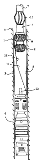
Referring to Figure 1, a borehole formed in a formation 1 is lined by a
tubular,
usually steel, casing 2. Positioned inside the casing is a whipstock 3 which,
once the
whipstock is appropriately oriented, is set in position within the casing by
an anchor
assembly 4 operated, for example, by a hydraulic guideline 5 or,
alternatively, the
anchor may be mechanically set. A one trip milling system 6 having a
longitudinal
axis is formed on a drill string collar 7 by the series connection of a first
mill 8 having
plural circumferentially disposed radially extending blades, a second mi119
also
having plural circumferentially disposed radially extending blades, and a so-
called
melon mill 10. At least some of the tapered blades and, preferably, all the
blades each
have a cutting surface formed of one or more of natural diamond,
polycrystalline
diamond and tungsten carbide. The first mill has a smaller diameter than the
second
-4-
CA 02590397 2007-06-28
mill as explained hereinafter.
Initially, as shown in Figure 2, the milling system 6 is secured to the
whipstock 3 by a releasable connection 21. Usually the releasable connection
is a
frangible bolt 21 secured to the whipstock and, initially, also to the milling
system, for
example the first mill 8.
The whipstock 3 has an outer surface which is arcuately formed to
approximately conform with the inside surface of the casing 2 and the
whipstock has
an internal arcuately formed concave surface for cooperating with mills of the
milling
system 6. The whipstock is provided with ramps 31, 32 and 33 longitudinally
spaced
along the whipstock, the ramps presenting an angle in the range 7 to 30 to
the casing
longitudinal axis and, preferably, 18 to the casing longitudinal axis. Three
ramps are
shown, although more ramps could be provided if desired. The ramps are
interspaced
by a substantially straight section 34, 35 presenting an angle of 0 - 5 to
the casing
longitudinal axis.
As shown in Figure 5, the ramp surfaces may be coated with diamond
elements or tungsten carbide elements 36 to provide abrasion resistance to the
milling
systems 6. The elements are, preferably, brazed to the whipstock and may have
flat or
domed outer surfaces. More or fewer elements than shown may be employed.
Each of the first mi118 and second mill 9 have plural blades 81, 91 having,
for
example, a parabolic shape with a substantially flat tapered portion 82, 92,
which are
each tapered in a direction in use to the bottom of the borehole to provide an
angle of
inclination to the longitudinal axis of the milling system of 7 to 30 ,
preferably 18 ,
and which is desirably conformed with the angle of the ramps 31, 32, 33 on the
whipstock. Located on a lower portion of some or, preferably, each of the
tapered
portions 82, 92 is a button element 83, 93 of hardened material, for example
natural
diamond or polycrystalline diamond. The button element 83, 93 is recessed in
an
aperture in at least some of the blades, preferably all the blades, such that
only 5% -
10% of the button element protrudes from the blade. Typically, the amount of
button
element protruding is approximately 0.8mm and the button element may have a
flat
or, preferably, convex outer surface to reduce abrasion against the ramps 31,
32, 33 of
-5-
CA 02590397 2007-06-28
the whipstock. Preferably, the button elements are provided on all of the
blades.
Both the blades 81, 91 have the tapered portion 82, 92 connected at a lower
end thereof to a more angled cutting surface 84, 94 and at the upper end of
the tapered
portion is a substantially vertically extending cutting surface 85, 95,
respectively
which, in turn, is connected to an inwardly inclined cutting portion 86, 96,
respectively. A lower end of the mill 8 is provided with an approximately
horizontal
cutting surface 87.
In operation, to perform sidetracking, the combination of whipstock and one
trip milling system are connected together by the bolt 21 in the position
shown in
Figure 2 and are lowered into the casing 2. When at the appropriate positional
height
within the casing, the anchor assembly 4, which is connected to the whipstock
by a
spigot 22, is oriented by rotation to have the desired polar coordinates to
sidetrack to a
new borehole location. The anchor assembly 4 is hydraulically set, in the
preferred
embodiment, via the hydraulic line 5 and the bolt 21 connection between the
whipstock and milling system 6 is released, preferably frangibly, to sheer the
bolt by
moving the milling system vertically, upwardly or downwardly. In this respect,
unlike the system shown in US-A-6648068, because the lower, first mi118 is not
connected against one of the ramps 31, 32, but is located in an intermediate
position,
so it is possible to sheer the bolt 21 in a downwards direction.
When the milling system 6 is released from the whipstock, so the milling
system is rotated and moved longitudinally downwardly within the casing 2 so
that
the button elements 83, 93 abrade the elements 36 on the ramps 31, 32. Because
of
the button elements 83, 93 and the elements 36, so the cutting milling
surfaces of the
mills 8, 9 are generally prevented from milling the ramps of the whipstock,
which is a
disadvantage of the prior art. Moreover, because it is arranged that the
distance
between the tapered portions of the first and second mills is the same as the
distance
between the ramps on the whipstock, so each mill 8, 9 has blades which engage
a
respective ramp, thereby sharing the downward force that is applied to the
milling
system. Thus, the cutting load is shared approximately evenly between the
ramps 31,
32 and it is, therefore, possible to increase the downward force using the
present
-6-
CA 02590397 2007-06-28
invention over the prior art where a single tapered mill engages a ramp. The
button
elements 83, 93 also reduce the risk of cutting into the whipstock rather than
the
casing.
In the position shown in Figure 3, the axially, longitudinally lower, first
mill 8
has an outer diameter which is smaller than that of the upstream second mill 9
and is
of such a diameter that it is able to be located alongside straight section 34
and the
second mill 9 has a diameter which is slightly less than the internal diameter
of the
casing 2. It is desirable that the cutting surface at least starts to cut the
window before
the button element touches the casing wall. With the mill blades moving
longitudinally down the respective ramps 31, 32, so the milling system is
deflected off
axis toward the right (as shown in the Figures) with the result that the
cutting surface
of the blades 91 starts to cut a window in the casing 2. With continued
movement
along the ramps 31, 32, so the first mill cutting surfaces are also brought
into contact
with the casing wall and commence milling a further window.
When the mills 8, 9 have traversed the straight section 35, 34, so the window
being milled by the upstream mil19 opens into the window milled by the first
mill 8.
Further downward movement of the mills 8, 9 causes them to move along ramps
32,
33 and for the milling system to be further deflected until as the blades of
mill 9
abrade ramp 33, so mill 8 is no longer in contact with the whipstock, but is
moved
into cutting formation as it then travels along a further straight section 36
and a
tapered section 37 having an angle typically in the range 3 to 15 to the
longitudinal
axis.
Because the leading mill, i.e. downstream, first mill 8 has a smaller diameter
than the mill 9, so greater rate of penetration is achievable particularly
through
formation. Continued downward movement of the milling system causes the mills
to
exit the casing 2 and to cut through formation 1 toward a new drilling
location.
It is to be understood that modifications could be made and that all such
modifications falling within the spirit and scope of the appended claims are
intended
to be included in the present invention.
-7-