Note: Descriptions are shown in the official language in which they were submitted.
CA 02590559 2007-06-12
WO 2006/065754 PCT/US2005/044949
1
SENSOR-DISPENSING INSTRUMENTS
FIELD OF THE INVENTION
[0001] The present invention generally relates to sensor-dispensing
instruments and,
more particularly, to sensor-dispensing instruments that are used in
determining the
concentration of an anayte (e.g., glucose) in a fluid.
BACKGROUND OF THE INVENTION
[0002] The quantitative determination of analytes in body fluids is of great
importance in
the diagnoses and maintenance of certain physiological abnormalities. For
example, lactate,
cholesterol and bilirubin should be monitored in certain individuals. In
particular,
determining glucose in body fluids is important to diabetic individuals who
must frequently
check the glucose level in their body fluids to regulate the glucose intake in
their diets.
[0003] The results of such tests can be used to determine what, if any,
insulin or other
medication needs to be administered. In one type of blood glucose testing
system, test
sensors are used to test a fluid such as a sample of blood. The test sensor
typically contains
biosensing or reagent material that will react with blood glucose. The testing
end of the
sensor is adapted to be placed into the fluid being tested, for example, blood
that has
accumulated on a person's finger after the finger has been pricked. The fluid
is drawn into a
capillary channel that extends in the sensor from the testing end to the
reagent material by
capillary action so that a sufficient amount of fluid to be tested is drawn
into the sensor. The
fluid then chemically reacts with the reagent material in the sensor. This
results in an
electrical signal indicative of the glucose level in the fluid being supplied
to contact areas
located near the rear or contact end of the test sensor.
[0004] The test sensors may be stored in the instrument (also referred to as a
meter) or,
alternatively, may be stored in a separate container from the instrument. Each
of such
embodiments have advantages and disadvantages. For example, it is desirable
for the test
sensors to be stored in the instrument such that all of the needed items are
located within one
device. There, however, are disadvantages in these systems such as the
instruments being
larger, more difficult for the user to operate and selected components having
reliability
issues.
CA 02590559 2007-06-12
WO 2006/065754 PCT/US2005/044949
2
[0005] It would be desirable to overcome the above-noted shortcoming of
existing
systems, while providing a simple, easy and user-friendly mechanism for
testing the
concentration of a desired analyte.
SUMMARY OF THE INVENTION
[0006] According to one embodiment, a sensor-dispensing instrument is adapted
to
determine an analyte concentration of a fluid and comprises a body, a cap, a
cartridge, a test-
sensor receptacle, a sensor-advancement mechanism, and a lancing device
including a lancet.
The cap is adapted to move between an open position and a closed position. The
cap and
body are' adapted to correspond with each other to form the closed position.
The cartridge
contains a plurality of test sensors. The cartridge is located substantially
within the cap. The
sensor-advancement mechanism is adapted to advance the plurality of test
sensors, one at a
time, to a position that allows a user to manually remove the test sensor and
place the test
sensor in the test-sensor receptacle.
[0007] According to another embodiment, a sensor-dispensing instrument is
adapted to
determine an analyte concentration of a fluid and comprises a body, a cap, a
cartridge, a test-
sensor receptacle, and a sensor-advancement mechanism. The cap is adapted to
move
between an open position and a closed position. The cap and body are adapted
to correspond
with each other to form the closed position. The cartridge contains a
plurality of test sensors.
The cartridge is located substantially within the cap. The sensor-advancement
mechanism is
adapted to advance the plurality of test sensors, one at a time, to a position
that allows a user
to manually remove the test sensor and place the test sensor in the test-
sensor receptacle.
[0008] According to a further embodiment, a sensor-dispensing instrument is
adapted to
determine an analyte concentration of a fluid and comprises a body, a cap, a
cartridge, a test-
sensor receptacle, a sensor-advancement mechanism, and a lancing device
including a lancet.
The cap is adapted to move between an open position and a closed position. The
cap and
body are adapted to correspond with each other to form the closed position.
The cartridge
contains a plurality of test sensors. The cartridge is located substantially
within the cap. The
sensor-advancement mechanism is adapted to automatically advance the plurality
of test
sensors, one at a time, to the test-sensor receptacle.
[0009] According to another embodiment, a sensor-dispensing instrument is
adapted to
determine an analyte concentration of a fluid and comprises a body, a cap, a
cartridge, a test-
CA 02590559 2007-06-12
WO 2006/065754 PCT/US2005/044949
3
sensor receptacle, and a sensor-advancement mechanism. The cap is adapted to
move
between an open position and a closed position. The cap and body are adapted
to correspond
with each other to form the closed position. The cartridge contains a
plurality of test sensors.
The cartridge is located substantially within the cap. The sensor-advancement
mechanism is
adapted to automatically advance the plurality of test sensors, one at a time,
to the test-sensor
receptacle.
[0010] According to one method, a sensor-dispensing instrument is provided
that
includes a body, a cap, a cartridge, a test-sensor-receptacle, a sensor-
advancing mechanism,
and a lancing device including a lancet. The cap is adapted to move between an
open
position and a closed position. The cap and body are adapted to correspond
with each other
to form the closed position. The cartridge contains a plurality of test
sensors. The cartridge
is located substantially within the cap. The sensor-advancement mechanism is
activated such
that the plurality of test sensors is advanced one at a time. The test sensor
is manually
removed and placed in the test-sensor receptacle. A fluid is generated using
the lancet and
placed on the test sensor. The analyte concentration of the fluid is
determined.
[0011] According to another method, a sensor-dispensing instrument is provided
that
includes a body, a cap, a cartridge, a test-sensor-receptacle, and a sensor-
advancing
mechanism. The cap is adapted to move between an open position and a closed
position.
The cap and body are adapted to correspond with each other to form the closed
position. The
cartridge contains a plurality of test sensors. The cartridge is located
substantially within the
cap. The sensor-advancement mechanism is activated such that the plurality of
test sensors is
advanced one at a time. The test sensor is manually removed and placed in the
test-sensor
receptacle. A fluid is placed on the test sensor. The analyte concentration of
the fluid is
determined.
[0012] According to a further method, a sensor-dispensing instrument is
provided that
includes a body, a cap, a cartridge, a test-sensor-receptacle, a sensor-
advancing mechanism,
and a lancing device including a lancet. The cap is adapted to move between an
open
position and a closed position. The cap and body are adapted to correspond
with each other
to form the closed position. The cartridge contains a plurality of test
sensors. The cartridge
is located substantially within the cap. The sensor-advancement mechanism is
activated such
that the sensor-advancement mechanism automatically advances the plurality of
test sensors,
CA 02590559 2007-06-12
WO 2006/065754 PCT/US2005/044949
4
one at a time, to the test-sensor receptacle. A fluid is generated using the
lancet and placed
on the test sensor. The analyte concentration of the fluid is determined.
[0013] According to another method, a sensor-dispensing instrument is provided
that
includes a body, a cap, a cartridge, a test-sensor-receptacle, and a sensor-
advancing
mechanism. The cap is adapted to move between an open position and a closed
position.
The cap and body are adapted to correspond with each other to form the closed
position. The
cartridge contains a plurality of test sensors. The cartridge is located
substantially within the
cap. The sensor-advancement mechanism is activated such that the sensor-
advancement
mechanism automatically advances the plurality of test sensors, one at a time,
to the test-
sensor receptacle. A fluid is placed on the test sensor. The analyte
concentration of the fluid
is determined.
BRIEF DESCRIPTION OF THE DRAWINGS
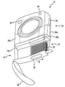
[0014] FIG. 1a is a front view of a sensor-dispensing instrument in a closed
position
according to one embodiment.
[0015] FIG. lb is a side view of the sensor-dispensing instrument of FIG. 1 a.
[0016] FIG. 1 c is a bottom view of the sensor-dispensing instrument of FIG. I
a.
[0017] FIG. 1d is a bottom perspective view of the sensor-dispensing
instrument of FIG.
I a in an open position.
[0018] FIG. 1 e is a front view of the sensor-dispensing instrument of FIG. I
a in an open
position with a test sensor being inserted.
[0019] FIG. 2a is a front view of a sensor-dispensing instrument in a open
position
according to another embodiment.
[0020] FIG. 2b is a top perspective view of the sensor-dispensing instrument
of FIG. 2a.
[0021] FIG. 3a is a front view of a sensor-dispensing instrument with a cap in
an open
position according to a further embodiment.
[0022] FIG. 3b is a side view of the sensor-dispensing instrument of FIG. 3a
with the cap
in a closed position.
[0023] FIG. 3c is an opposing side view of the sensor-dispensing instrument of
FIG. 3a
with the cap in a closed position.
[0024] FIG. 3d is a front view of the sensor-dispensing instrument of FIG. 3a
with the
cap in a closed position.
CA 02590559 2007-06-12
WO 2006/065754 PCT/US2005/044949
[0025] FIG. 4a is a front view of a sensor-dispensing instrument in an open
position
according to yet another embodiment.
[0026] FIG. 4b is a side view of the sensor-dispensing instrument of FIG. 4a.
[0027] FIG. 5 is a front view of a cartridge according to one embodiment.
[0028] While the invention is susceptible to various modifications and
alternative forms,
specific embodiments are shown by way of example in the drawings and are
described in
detail herein. It should be understood, however, that the invention is not
intended to be
limited to the particular forms disclosed. Rather, the invention is to cover
all modifications,
equivalents, and alternatives falling within the spirit and scope of the
invention.
DETAILED DESCRIPTION OF THE ILLUSTRATED EMBODIMENTS
[0029] The sensor-dispensing instruments of the present invention such as
shown in
FIGS. 1-4 are used to determine analyte concentrations. Analytes that may be
measured
using the present invention include glucose, lipid profiles (e.g.,
cholesterol, triglycerides,
LDL and HDL), microalbumin, hemoglobin A1C, fructose, lactate, or bilirubin.
The present
invention is not limited, however, to these specific analytes and it is
contemplated that other
analyte concentrations may be determined. The analytes may be in, for example,
a whole
blood sample, a blood serum sample, a blood plasma sample, or other body
fluids like ISF
(interstitial fluid) and urine.
[0030] Referring to FIGS. la-e, a sensor-dispensing instrument 10 is shown
according to
one embodiment. The sensor-dispensing instrument 10 comprises a cap 12, a body
14, a
cartridge 16 that includes a plurality of test sensors 18, and a sensor-
advancement mechanism
20.
[0031] The cap 12 is adapted to move between an open and a closed position. In
the
closed position, the cap 12 of FIG. 1 a corresponds to the body 14 and
desirably forms a snug
fit that prevents or inhibits contamination from entering into the sensor-
dispensing instrument
10. The cap 12 assists in protecting the cartridge 16, electrical connections
in the sensor-
dispensing instrument, and a lancing device 24 that includes a lancet 30. The
cap 12 may be
adapted to correspond to either the top surface 14a of the body 14 (see FIG. 1
a) or the bottom
surface 14b of the body 14 (see FIG. ld) as shown in this embodiment.
[0032] It is advantageous for a cap to be adapted to attach to the top and
bottom surface
of the body so as to provide a convenient location to place the cap when the
user is
CA 02590559 2009-10-22
6
performing operations with the sensor-dispensing instrument such as, for
example, drawing a
bodily fluid, handling a test sensor, or waiting for the determination of an
analyte
concentration. In such an embodiment, the cap and body are typically not
attached or are
detachably connected.
[0033] The cartridge 16 is located substantially within the cap 12. The
cartridge 16 is
desirably located entirely within the cap 12, such as shown in FIGS. la, Id.
The cartridge 16
contains the plurality of test sensors 18 that is adapted to assist in
determining the analyte
concentration of the fluid sample. In one embodiment, the plurality of test
sensors 18 is
stacked horizontally within the cap 12, as shown in FIGS. 1 a, 1 d. The
plurality of test sensors
may also be stacked vertically within the cap (see, e.g., plurality of test
sensors 118 in FIGS.
2a, 2b). The plurality of test sensors 18 may be adapted for either
electrochemical or optical
measurement.
[0034] Referring to an alternate embodiment of the present invention as
exhibited in FIG.
5, a cartridge 50 is shown that may be used in the sensor-dispensing
instrument 10. The
cartridge 50 includes a housing 52 and a plurality of test sensors 54. The
plurality of test
sensors 54 are moved in the direction of arrow A via a spring 56. The
cartridge 50 also
includes a plurality of moveable seals 58a,b that protects the plurality of
test sensors 54 from
the humidity. More specifically, the seals 58a,b prevent or inhibit air and
moisture from
entering into the interior of the cartridge 50 that contains the plurality of
test sensors 54. The
plurality of test sensors 54, one at a time, exit the cartridge 50, via an
opening 60. The
plurality of test sensors 54 may be removed one at a time by using, for
example, a pusher
assembly to penetrate the moveable seals, contact one of the plurality of test
sensors 54 and
push or extract one of the test sensors 54 from the cartridge 50 via the
opening 60. Such a
cartridge, as well as other embodiments of cartridges, are disclosed in
published U.S.
Application No. 2008/0131322 that was filed on June 24, 2004, and entitled
"Cartridge and
Sensor-Dispensing Instrument." It is contemplated that other cartridges, which
contain the
plurality of test sensors, may be used in the sensor-dispensing instrument.
The test sensors in
other cartridges may be dispensed in a different manner than depicted in FIG.
5.
[0035] Referring back to FIGS. 1 a-e, the cap 12 includes a flip-lid mechanism
22 that is
adapted to move between an open and a closed position. When the flip-lid
mechanism 22 is
in the open position (see FIG. l d), the cartridge 16 and the sensor-
advancement mechanism
20 are exposed. When the flip-lid mechanism 22 is in an open position, the
cartridge can be
CA 02590559 2009-10-22
7
accessed. It is contemplated that the flip-lid mechanism in the open position
may only
expose the sensor-advancement mechanism and not the cartridge. The flip-lid
mechanism 22
desirably has a snug fit that prevents or inhibits contamination from entering
into the sensor-
dispensing instrument 10. The flip-lid mechanism may have a seal instead of or
in addition
to the cartridge for preventing or inhibiting the atmosphere (i.e., moisture)
from entering into
the cartridge.
100361 The sensor-advancement mechanism 20 is adapted to advance the plurality
of test
sensors 18 from the cartridge 16 one at a time. The sensor-advancement
mechanism 20 of
FIG. 1 d is moved in the direction of arrow B to advance the plurality of test
sensors 18 from
the cartridge 16 one at a time. The sensor-advancement mechanism 20 may, for
example, be
a variety of mechanisms able to extract the plurality of test sensors 18, one
at a time, from the
cartridge 16. The plurality of test sensors 18 may be pulled or pushed from
the cartridge 16.
100371 To assist in positioning the next one of the plurality of test sensors
to be extracted,
at least one spring 42 may be used that moves the plurality of test sensors 18
in the direction
of arrow C in FIG. I a.
[00381 When the flip-lid mechanism 22 is in the open position, the user may
advance one
of the plurality of test sensors 18, or replace the cartridge 16. In the
closed position, the flip-
lid mechanism 22 protects (a) against inadvertent advancement of one the
plurality of test
sensors 18, and (b) the plurality of test sensors 18 from being exposed to the
environment.
100391 To protect the plurality of test sensors, desiccant material 44 is
desirably added to
the cartridge 16 to assist in maintaining an appropriate humidity level within
the interior
thereof that contains the plurality of test sensors 18. By maintaining an
appropriate humidity
level, reagent material in the test sensors, if used, is protected. The amount
of desiccant
material 44 should be sufficient to obtain the desired shelf-life (the time
period before any of
the plurality of test sensors are used). The amount of desiccant material 44
should also be
sufficient to obtain the desired use-life (the time period after first use of
one of the plurality
of test sensors).
[00401 The desiccant may be in the form of several shapes including balls,
tablets,
granular, or paper. For example, the desiccant may be molecular sieve spheres
or thick
desiccant paper. The desiccant may be placed within the cartridge 16 as shown
with
desiccant material 44. The desiccant may be molded into an interior surface of
the housing of
the cartridge 16 so as to absorb moisture within the same. One non-limiting
example of
CA 02590559 2007-06-12
WO 2006/065754 PCT/US2005/044949
8
desiccant material may be purchased from Multisorb of Buffalo, New York in the
form of,
for example, molecular sieve beads.
[0041] To allow viewing of the remaining ones of the test sensors 18, the cap
12 of the
sensor-dispensing instrument 10 is typically translucent. The cap 12, however,
may be
adapted to allow viewing of the plurality of test sensors 18 by having the cap
12 form a
window.
[0042] The cartridge 16 also includes a calibration information device 26 (see
FIG. 1 a)
that contains information about the plurality of test sensors 18 and is used
to assist in
calibrating the sensor-dispensing instrument 10. The calibration information
device 26 is
typically connected to a calibration read mechanism 27 of the instrument 10.
The calibration
information device 26 may contain calibration information such as sensitivity
to the reagent
or temperature profiles, date of manufacture, and date of expiration. The
device 26 may be in
the form of a memory device such as an EPROM, an electrical barcode-type
label, an optical
barcode-type label, an RF label or other forms that are adapted to store or
convey calibration
information. The electrical barcode-type label may be a plurality of
electrical contacts that is
connected to the calibration read mechanism and conveys information about the
calibration
based on a programmed conductive pattern. Using a calibration information
device such as
an optical barcode-type label or an RF label does not require the use of a
physical connection
to a calibration read mechanism.
[0043] The information may be read optically or electronically. The sensor-
dispensing
instrument 10 may be adapted to calibrate upon closure of the cap 12.
[0044] The cap 12 may be disposable such that the user disposes of the cap 12
after each
of the plurality of test sensors 18 has been used. Subsequently, a user would
typically place a
second identical cap that includes a cartridge with a plurality of unused test
sensors.
Alternatively, the cap 12 may be reusable with only the cartridge 16 being
disposed of after
the plurality of test sensors has been used. In such an embodiment, after each
of the plurality
of test sensors 18 has been used, the user removes the cartridge 16 from the
cap 12 of the
sensor-dispensing instrument 10 and replaces it with a second identical
cartridge that includes
a plurality of unused test sensors.
[0045] The body 14 of the sensor-dispensing instrument 10 includes a test-
sensor
receptacle 28. To prepare the sensor-dispensing instrument 10 for testing,
according to one
method, the cap 12 is placed in the open position, which exposes the lancing
device 24 and
CA 02590559 2007-06-12
WO 2006/065754 PCT/US2005/044949
9
the test-sensor receptacle 28. The cap 12 may then be attached to the bottom
surface 14b of
the body 14 for convenience. The flip-lid mechanism 22 (see FIG. Id) is opened
to expose
the sensor-advancement mechanism 20 and the plurality of test sensors 18.
[0046] The user slides the sensor-advancement mechanism 20 causing one of the
plurality of test sensors 18 to advance from the cartridge 16. It is
contemplated that the user
may activate the sensor-advancement mechanism 20 by other methods such as
pressing a
button or pulling the plurality of test sensors 18 from the stack by hand.
[0047] The user then manually grasps and places the test sensor in the test-
sensor
receptacle 28. The test-sensor receptacle 28 may be situated at an angle, such
as in FIGS. la,
le to facilitate alternate site testing and easier loading. For example, a
test sensor 18a is
shown situated at an angle in the test-sensor receptacle 28 in FIG. le. It is
contemplated,
however, that the test-sensor receptacle 28 may be generally perpendicular or
perpendicular
to the top surface 14a of the body 14.
[0048] Referring to FIGS. la, le, the body 14 of the sensor-dispensing
instrument 10
depicts the lancing device 24 that includes (a) the lancet 30, (b) a lancing
portion 24a that
holds the lancet 30, and (c) a lancing endcap 24b that protects the user from
inadvertently
contacting the lancet 30. The lancet 30 is adapted to obtain a fluid sample
from the user. The
lancet 30 is typically retractable. The lancing device 24 is adjacent to the
test-sensor
receptacle 28 for convenient side-by-side lancing and testing that reduces the
required level
of component manipulation by the user. It is contemplated, however, that the
lancing device
and the test-sensor receptacle may be located in different positions with
respect to each other.
[0049] As shown in FIGS. 1a, lb, the body 14 includes a cocking device 32 and
a firing
mechanism 34. According to one embodiment, the cocking device 32 is used to
prepare the
lancing device 24 for firing, and the firing mechanism 34 fires the lancet 30
via the lancing
device 24. The cocking device 32 and firing mechanism 34 may be separate, as
shown in
FIGS. la, lb, or combined together.
[0050] To provide enhanced storage options to a user, the body 14 may form a
storage
compartment 36 such as shown in FIG. lc that is adapted to store a plurality
of lancets,
additional cartridges, test sensors and/or other items. Thus, the user may
conveniently carry a
sensor-dispensing instrument that includes replacement components of the
system.
[0051] The storage compartment 36 may be referred to as self-contained storage
since the
storage compartment 36 is located within the sensor-dispensing instrument 10.
Additionally,
CA 02590559 2007-06-12
WO 2006/065754 PCT/US2005/044949
the components to be stored in the storage compartment 36 may be used
components or
replacement components such as lancets, cartridges and test sensors. This
allows for easier
transport and/or storage of necessary testing supplies as well as a discrete
way to dispose of
used supplies until permanent discarding is desired. The used components are
typically
stored until a more permanent waste container is accessible. The storage
compartment 36
may further include additional items such as desiccant if, for example, test
sensors are being
stored. To prevent or inhibit contamination, it is desirable to have separate
storage areas for
the used and replacement components. It is also desirable to have a hygienic
sleeve for the
storage compartment or portion thereof that is adapted to contain used
components.
[0052] The storage compartment 36 shown in FIG. Ic is permanently formed by
the body
14. It is contemplated that a storage compartment may be detachably added to
the body.
Thus, in such an embodiment, the storage compartment is removable by the user.
Such a
storage compartment may include used components or replacement components such
as
lancets, cartridges and test sensors as discussed above.
[0053] Furthermore, the storage compartment does not need to be in the exact
location
depicted in FIG. 1c. For example, the storage compartments may be formed in
other
locations within the body 14 or even the cap 12. As shown in FIG. 1 a, storage
compartments
60a-c are shown as being formed within the body 14. As discussed above, the
storage
compartments 60a-c may include used components or replacement components such
as
lancets, cartridges and test sensors as discussed above. It is contemplated
that there may be
less or more of the storage compartments than shown in FIG. 1a. The storage
compartments
60a-c may be used in addition to, or instead of, the storage compartment 36.
[0054] The sensor-dispensing instrument 10 may include a detection mechanism
that
detects whether the cap and/or flip lid is in a closed position. For example,
the sensor-
dispensing instrument may include a detection mechanism 46 such as a contact
switch that
alerts the user when the cap is not in the closed position. This alert may be
provided to the
user via an audible signal. This is especially desirable if the cap in the
closed position
provides the main source of protecting the test sensors from being exposed to
humidity from
the environment. The cap 12 may also be designed to provide a seal that
assists in preventing
or inhibiting moisture from being exposed to the plurality of test sensors 18.
[0055] The sensor-dispensing instrument 10, as shown in FIG. Id, includes a
navigation
control 38 that is adapted to navigate the testing and test-result options
available to the user.
CA 02590559 2007-06-12
WO 2006/065754 PCT/US2005/044949
11
Additionally, referring to FIGS. la, ld, the sensor-dispensing instrument 10
includes an
ejection mechanism 40 that is adapted to release one of the plurality of test
sensors 18 after
testing.
[0056] Ejection may be accomplished by several methods. In one method, the
sensor-
dispensing instrument may include an ejection mechanism that ejects the used
test sensor
from the sensor-dispensing instrument. In such an embodiment, the test sensor
is released
forcefully. In another method, the test sensors may be ejected by (a)
releasing a grip of the
test sensors, and (b) tipping the sensor-dispensing instrument such that the
test sensor falls
from the test-sensor receptacle via gravity. In a further method, the test
sensor may also be
removed manually from the sensor-dispensing instrument by grasping and pulling
the test
sensor from the sensor-dispensing instrument.
[0057] The plurality of test sensors utilized by the sensor-dispensing
instrument is
typically provided with a capillary channel that extends from the front or
testing end of the
sensors to biosensing or reagent material disposed in the sensor. When the
testing end of the
sensor is placed into fluid (e.g., blood that is accumulated on a person's
finger after the finger
has been pricked by the lancet), a portion of the fluid is drawn into the
capillary channel by
capillary action. The fluid then chemically reacts with the reagent material
in the test sensor
so that an electrical signal indicative of the analyte concentration (e.g.,
glucose concentration)
in the fluid is supplied and subsequently transmitted to an electrical
assembly.
[0058] The results of the analysis may then be displayed such as on a liquid
crystal
display of the sensor-dispensing instrument. Some of the information that may
be displayed
when the sensor-dispensing instrument include the following: a battery
indication, a
numerical display, an indication of the number of sensors remaining, an
indication to load a
cartridge into the sensor-dispensing instrument, apply blood indication, a
temperature
indication, or various combinations thereof. It is contemplated that other
types of displays
may be used.
[0059] According to one testing process, a whole blood sample may be prepared
for
testing by (a) advancing one of the test sensors and manually placing the test
sensor in the
test-sensor receptacle to receive a whole blood sample; (b) generating a whole
blood sample
via the lancing device; and (c) bringing the test sensor and the whole blood
sample into
contact wherein the blood is generally drawn into the sensor by capillary
action.
CA 02590559 2007-06-12
WO 2006/065754 PCT/US2005/044949
12
[0060] FIGS. 2a, 2b illustrate a sensor-dispensing instrument according to
another
embodiment. The sensor-dispensing instrument 110 of FIGS. 2a, 2b includes some
similar
features to the sensor-dispensing instrument 10 of FIGS. la-e. The sensor-
dispensing
instrument 110 comprises a cap 112, a body 114, a cartridge 116 that includes
the plurality of
test sensors 118, and a sensor-advancement mechanism 120. The sensor-
dispensing
instrument 110 of FIGS. 2a, 2b, however, does not include, for example, a
lancing device,
cocking device, firing mechanism, or storage space for a plurality of lancets
as depicted in the
sensor-dispensing instrument 10 of FIGS. 1 a-e.
[0061] The cap 112 is adapted to move between an open and a closed position.
In the
closed position, the cap 112 corresponds to the body 114 and desirably forms a
snug fit that
prevents or inhibits contamination from entering into the sensor-dispensing
instrument 110.
As shown in FIG. 2a, the cap 112 is attached to the body 114 of the sensor-
dispensing
instrument 110 via a hinge 115. It is advantageous for a cap to be attached to
the body via a
hinge so as to secure the cap when the user is performing operations with the
sensor-
dispensing instrument such as, for example, handling the test sensor or
waiting for the analyte
concentration to be determined. Since the cap 112 and the body 114 are
attached via the
hinge 115, it may be desirable for the cap 112 to be reused and the cartridge
to be disposable.
It is contemplated, however, that the cap and the body may be detachable
connected via the
hinge such that the cap may be disposable.
[0062] The cap 112 of FIGS. 2a, 2b includes the sensor-advancement mechanism
120,
the cartridge 116, a flip-lid mechanism 122, and a window 142 adapted to allow
viewing of
the remaining plurality of test sensors 118. The cap, however, may also be
opaque, or
adapted to allow viewing of the plurality of test sensors by other methods.
The plurality of
test sensors 118 is adapted for either electrochemical or optical measurement.
As shown in
FIGS. 2a, 2b, the plurality of test sensors 118 is stacked vertically in the
cap 112. The
cartridge 116 includes a calibration information device 126 that is adapted to
store or convey
calibration information to a calibration read mechanism 127 of the instrument
110. It is
contemplated that other cartridges may be used in the sensor-dispensing
instrument 110.
[0063] The body 114 of the sensor-dispensing instrument 110 of FIGS. 2a, 2b
includes a
test-sensor receptacle 128, an ejection mechanism 140, and a navigation
control 138. To
prepare the sensor-dispensing instrument 110 for testing, according to one
method, the user
slides the sensor-advancement mechanism 120 causing one of the plurality of
test sensors 118
CA 02590559 2007-06-12
WO 2006/065754 PCT/US2005/044949
13
to advance from the cartridge 116. It is contemplated that the user may
activate the sensor-
advancement mechanism 120 by other methods such as pressing a button. The user
then
manually places the test sensor in the test-sensor receptacle 128. It is
contemplated that the
body 114 may be designed to include a storage space for lancets, such as
storage
compartment 36 and storage compartments 60a-c discussed above in FIGs. la, lc.
[0064] Referring to FIGS. 3a-d, a sensor-dispensing instrument is shown
according to a
further embodiment. A sensor-dispensing instrument 210 of FIGS. 3a-d comprises
a cap 212,
a body 214, a cartridge 216 that includes a plurality of test sensors 218, and
a sensor-
advancement mechanism 220.
[0065] The cap 212 is adapted to move between an open and a closed position.
In the
closed position of FIG. 3d, the cap 212 corresponds to the body 214 and
desirably forms a
snug fit that prevents or inhibits contamination from entering the sensor-
dispensing 210. The
cap 212 of FIG. 3a is removable from the body 214 and may be adapted to
correspond to
either a top surface 214a or a bottom surface 214b of the body 214.
[0066] It is advantageous for a cap to be adapted to attach to the top and
bottom surfaces
of the body so as to provide a convenient location to place the cap when the
user is
performing operations with the sensor-dispensing instrument such as, for
example, drawing a
bodily fluid or waiting for the analyte concentration to be determined. In
such an
embodiment, the cap and body are typically not attached or are detachably
connected.
[0067] The cartridge 216 is located substantially within the cap 212. The
cartridge 216 is
desirably located entirely within the cap 212 as shown, for example, in FIG.
3a. The
cartridge 216 contains the plurality of test sensors 218 that is adapted to
assist in determining
the analyte concentration of the fluid sample. As shown in the embodiment of
FIG. 3a, the
plurality of test sensors 218 is stacked vertically in the cap 212. The
plurality of test sensors
218 is adapted for either electrochemical or optical measurement.
[0068] As noted previously, the cap 212 is adapted to move between an open and
a closed
position. When the cap 212 is detached from the body 214 (i.e., in an open
position), a
lancing device 224, the cartridge 216, and a test-sensor receptacle 228 are
exposed and
accessible. The cartridge 216 (see FIG. 3a) includes a calibration information
device 226 as
discussed above that is adapted to store or convey calibration information to
a calibration
read mechanism 227 of the instrument 210. The sensor-advancement mechanism 220
is
adapted to advance the plurality of test sensors 218 from the cartridge 216
one at a time. In
CA 02590559 2007-06-12
WO 2006/065754 PCT/US2005/044949
14
the open position, the user may replace the cartridge 216 according to one
embodiment. In
the closed position, the cap 212 protects the test-sensor receptacle 228, the
calibration read
mechanism 227 and the lancing device 224. The cap 212 may also be designed to
provide a
seal that assists in preventing or inhibiting moisture from being exposed to
the plurality of
test sensors 218.
[0069] To allow viewing of the remaining ones of the plurality of test sensors
218, the
cap 212 of the sensor-dispensing instrument 210 of FIGS. 3a-d is typically
translucent. The
cap 212, however, may be adapted to allow viewing of the plurality of test
sensors 218 by
having the cap 212 form a window. The sensor-dispensing instrument 210 may be
adapted to
calibrate upon closure of the cap 212.
[0070] The cap 212 may be disposable such that the user disposes of the cap
212 after
each of the plurality of test sensors 218 has been used. Subsequently, a user
would typically
place a second identical cap that includes a cartridge with a plurality of
unused test sensors.
Alternatively, the cap 212 may be reusable with only the cartridge 216 being
disposed after
the plurality of test sensors has been used. In such an embodiment, after each
of the plurality
of test sensors 218 has been used, the user removes the cartridge 216 from the
cap 212 of the
sensor-dispensing instrument 210 and replaces it with a second identical
cartridge that
includes a plurality of unused test sensors.
[0071] The body 214 of the sensor-dispensing instrument 210 includes the test-
sensor
receptacle 228. To prepare the sensor-dispensing instrument 210 for testing,
according to one
method, the sensor-dispensing instrument 210 is placed in a closed position
(see FIG. 3d).
During the closed position, the user slides the sensor-advancement mechanism
220 causing
one of the plurality of test sensors 218 to advance from the cartridge 216.
The plurality of
test sensors 218 is moved one at a time in the direction of arrow D. The
sensor-dispensing
instrument 210 automatically moves one of the test sensors 218 into the test-
sensor receptacle
228 without any manual handling of the test sensor. It is advantageous for the
sensor-
advancement mechanism 220 to place the test sensors 218, one at a time,
directly into the
test-sensor receptacle 228 so as to reduce the requisite amount of user
manipulation. To
continue the testing process, the user removes the cap 212 from the body 214
(see open
position of FIG. 3a). FIG. 3a shows the automatically placed test sensor 218a
in the test-
sensor-receptacle 228.
CA 02590559 2007-06-12
WO 2006/065754 PCT/US2005/044949
[0072] Referring still to FIG. 3a, the body 214 of the sensor-dispensing
instrument 210
includes the lancing device 224 that includes (a) a lancet 230, (b) a lancing
portion 224a that
holds the lancet 230, and (c) a lancing endcap 224b that covers and protects
the user from
inadvertently contacting the lancet 230. In the sensor-dispensing instrument
210 of FIG. 3a,
the lancing device 224 is adjacent to the test-sensor receptacle 228 for
convenient side-by-
side lancing and testing that reduces the required level of component
manipulation by the
user. It is contemplated, however, that the lancing device and the test-sensor
receptacle may
be located in different positions with respect to each other.
[0073] As shown in FIGS. 3a, 3b, the body 214 includes a cocking device 232
and a
firing mechanism 234. According to one embodiment, the cocking device 232 is
used to
prepare the lancing device 224 for firing, and the firing mechanism 234 fires
the lancet 230
via the lancing device 224. Before the firing mechanism 234 fires the lancet
230, the lancing
endcap 224b is removed from the lancing portion 224a to expose the lancet 230.
The cocking
device 232 and firing mechanism 234 may be separate, as shown in FIGS. 3a, 3b,
or
combined together.
[0074] To provide enhanced storage options to a user, the body 214 forms a
storage
compartment 236 (see FIGS. 3b, 3c) that is adapted to store a plurality of
lancets, additional
cartridges, test sensors and/or other items. Thus, the user may conveniently
carry a sensor-
dispensing instrument that includes replacement components of the system.
[0075] The storage compartment 236 may be referred to as self-contained
storage.
Additionally, the components to be stored in the storage compartment 236 may
be used
components or replacement components such as lancets, cartridges and test
sensors. The
storage compartment 236 may further include additional items such as desiccant
if, for
example, test sensors are being stored. To prevent or inhibit contamination,
it is desirable to
have separate storage areas for the used and replacement components. It is
also desirable to
have a hygienic sleeve for the storage compartment or portion thereof that is
adapted to
contain used components. The used components are typically stored until a more
permanent
waste container is accessible.
[0076] The storage compartment 236 shown in FIGs. 3b, 3c is permanently formed
by the
body 214. It is contemplated that a storage compartment may be detachably
added to the
body. Thus, in such an embodiment, the storage compartment is removable by the
user.
CA 02590559 2007-06-12
WO 2006/065754 PCT/US2005/044949
16
Such a storage compartment may include used components or replacement
components such
as lancets, cartridges and test sensors as discussed above.
[0077] Furthermore, the storage compartment does not need to be in the exact
location
depicted in FIGs. 3b, 3c. For example, the storage compartments may be formed
in other
locations within the body 214 or even the cap 212. As shown in FIG. 3a,
storage
compartments 260a, 260b are shown as being formed within the body 14. As
discussed
above, the storage compartments 260a, 260b may include used components or
replacement
components such as lancets, cartridges and test sensors as discussed above. It
is
contemplated that there may be less or more of the storage compartments than
shown in FIG.
3a. The storage compartments 260a, 260b may be used in addition to, or instead
of, the
storage compartment 236.
[0078] The sensor-dispensing instrument 210 may include a detection mechanism
that
detects whether the cap is in a closed position. For example, the sensor-
dispensing
instrument may include a detection mechanism 246 such as a contact switch that
alerts the
user when the cap is not in the closed position. This alert may be provided to
the user via an
audible signal. This is especially desirable if the cap in the closed position
provides the main
source of protecting the test sensors from being exposed to humidity from the
environment.
[0079] The sensor-dispensing instrument 210 includes a navigation control 238
(see FIG.
3c) that is adapted to navigate the testing and test-result options available
to the user.
Additionally, referring to FIG. 3a, the sensor-dispensing instrument 210
includes an ejection
mechanism 240 that is similar to described above with the ejecting mechanism
40. Ejection
of a test sensor from the sensor-dispensing instrument may be accomplished in
a similar
manner as discussed above with respect to the sensor-dispensing instrument 10
of FIG. 1.
[0080] FIGS. 4a, 4b illustrate a sensor-dispensing instrument according to
another
embodiment. The sensor-dispensing instrument 310 includes some similar
features to the
sensor-dispensing instrument 210 of FIGS. 3a-d. The sensor-dispensing
instrument 310 of
FIGS. 4a, 4b comprises a cap 312, a body 314, a cartridge 316 that includes a
plurality of test
sensors 318, and a sensor-advancement mechanism 320. The sensor-dispensing
instrument
310 of FIGS. 4a, 4b, however, does not include, for example, a lancing device,
cocking
device, or firing mechanism as depicted in the sensor-dispensing instrument
210 of FIGS. 3a-
d.
CA 02590559 2007-06-12
WO 2006/065754 PCT/US2005/044949
17
[0081] The cap 312 is adapted to move between an open and a closed position.
In the
closed position, the cap 312 corresponds to the body 314 and desirably fonns a
snug fit that
prevents or inhibits contamination from entering into the sensor-dispensing
instrument 310.
As shown in FIG: 4a, the cap 312 is attached to the body 314 of the sensor-
dispensing
instrument 310 via a hinge 315. It is advantageous for a cap to be attached to
the body via a
hinge so as to secure the cap when the user is performing operations with the
sensor-
dispensing instrument such as, for example, waiting for the analyte
concentration to be
determined.
[0082] The cap 312 includes the sensor-advancement mechanism 320, the
cartridge 316
and a window 342 adapted to allow viewing of the plurality of test sensors
318. The plurality
of test sensors 318 is adapted for either electrochemical or optical
measurement. The
cartridge 316 (see FIG. 4a) includes a calibration information device 326 as
discussed above
that is adapted to store or convey calibration information to a calibration
read mechanism 327
of the instrument 310.
[0083] The body 314 of the sensor-dispensing instrument 310 of FIGS. 4a-b
includes a
test-sensor receptacle 328, a storage compartment 336, an ejection mechanism
340, and a
navigation control 338. The storage compartment 336 is adapted to store a
plurality of
lancets, additional cartridges, test sensors and/or other items. It is
contemplated that other
storage compartments may be used instead of, or in addition to storage
compartment 336.
Some non-limiting examples of other storage compartments may be storage
compartments
60a-c of FIG. I a.
[0084] To prepare the sensor-dispensing instrument 310 for testing, according
to one
method, the sensor-dispensing instrument 310 is placed in an closed position.
The user slides
the sensor-advancement mechanism 320 causing one of the plurality of test
sensors 318 to
advance from the cartridge 316. It is contemplated that the user may activate
the sensor-
advancement mechanism 320 by other methods such as pressing a button. The
sensor-
dispensing instrument 310 automatically moves one of the test sensors 318 into
the test-
sensor receptacle 328 without any manual handling of the test sensor. This is
shown in FIG.
4a where a test sensor 318a is located in the test-sensor receptacle 328. It
is advantageous for
the sensor-advancement mechanism 320 to place the test sensors 318, one at a
time, directly
into the test-sensor receptacle 328 so as to reduce the requisite amount of
user manipulation.
CA 02590559 2007-06-12
WO 2006/065754 PCT/US2005/044949
18
The sensor-dispensing instrument 310 may be moved to open position to continue
the testing
process by moving the cap 312 with respect to the body 314 via the hinge 315.
[0085] Alternate Embodiment A
A sensor-dispensing instrument adapted to determine an analyte concentration
of a
fluid, the instrument comprising:
a body;
a cap being adapted to move between an open position and a closed position,
the cap
and body being adapted to correspond with each other to form the closed
position;
a cartridge' containing a plurality of test sensors, the cartridge being
located
substantially within the cap;
a test-sensor receptacle;
a sensor-advancement mechanism being adapted to advance the plurality of test
sensors, one at a time, to a position that allows a user to manually remove
the test sensor and
place the test sensor in the test-sensor receptacle; and
a lancing device including a lancet.
[0086] ALTERNATE EMBODIMENT B
The sensor-dispensing instrument of Alternate Embodiment A further including a
cocking device adapted to prepare the lancet for firing.
[0087] ALTERNATE EMBODIMENT C
The sensor-dispensing instrument of Alternate Embodiment A further including a
firing mechanism adapted to fire the lancet.
[0088] ALTERNATE EMBODIMENT D
The sensor-dispensing instrument of Alternate Embodiment A wherein the lancing
device is adjacent to the test-sensor receptacle.
[0089] ALTERNATE EMBODIMENT E
The sensor-dispensing instrument of Alternate Embodiment A wherein the lancing
device includes a lancing endcap.
[0090] ALTERNATE EMBODIMENT F
The sensor-dispensing instrument of Alternate Embodiment A wherein the body
forms a storage compartment adapted to store a plurality of lancets, test
sensors or a
cartridge.
CA 02590559 2007-06-12
WO 2006/065754 PCT/US2005/044949
19
[0091] ALTERNATE EMBODIMENT G
The sensor-dispensing instrument of Alternate Embodiment A wherein the
plurality of
sensors is electrochemical sensors.
[0092] ALTERNATE EMBODIMENT H
The sensor-dispensing instrument of Alternate Embodiment A wherein the
plurality of
sensors is optical sensors.
[0093] ALTERNATE EMBODIMENT I
The sensor-dispensing instrument of Alternate Embodiment A wherein the cap is
adapted to be removable from the body.
[0094] ALTERNATE EMBODIMENT J
The sensor-dispensing instrument of Alternate Embodiment A wherein the body
has a
top surface and a bottom surface, the cap being adapted to correspond with the
top surface
and the bottom surface of the body.
[0095] ALTERNATE EMBODIMENT K
The sensor-dispensing instrument of Alternate Embodiment A wherein the cap is
connected to the body via a hinge.
[0096] ALTERNATE EMBODIMENT L
The sensor-dispensing instrument of Alternate Embodiment A further including a
detection mechanism that alerts a user when the cap is not in the closed
position.
[0097] ALTERNATE EMBODIMENT M
The sensor-dispensing instrument of Alternate Embodiment A wherein the cap in
the
closed position allows viewing of the plurality of test sensors.
[0098] ALTERNATE EMBODIMENT N
The sensor-dispensing instrument of Alternate Embodiment M wherein the cap
forms
a window.
[0099] ALTERNATE EMBODIMENT 0
The sensor-dispensing instrument of Alternate Embodiment A wherein the
cartridge
further includes a calibration information device that contains calibration
information about
the plurality of test sensors.
[00100] ALTERNATE EMBODIMENT P
The sensor-dispensing instrument of Alternate Embodiment A wherein the
plurality of
test strips is stacked horizontally within the cap.
CA 02590559 2007-06-12
WO 2006/065754 PCT/US2005/044949
[00101] ALTERNATE EMBODIMENT Q
The sensor-dispensing instrument of Alternate Embodiment A wherein the
plurality of
test strips is stacked vertically within the cap.
[00102] ALTERNATE EMBODIMENT R
The sensor-dispensing instrument of Alternate Embodiment A wherein the
cartridge is
located entirely within the cap.
[00103] ALTERNATE EMBODIMENT S
The sensor-dispensing instrument of Alternate Embodiment A further including
an
ejection mechanism adapted to eject one of the plurality of test sensors from
the test-sensor
receptacle.
[00104] ALTERNATE EMBODIMENT T
The sensor-dispensing instrument of Alternate Embodiment A wherein the cap
includes a flip-lid mechanism.
[00105] ALTERNATE EMBODIMENT U
A sensor-dispensing instrument adapted to determine an analyte concentration
of a
fluid, the instrument comprising:
a body;
a cap being adapted to move between an open position and a closed position,
the cap
and body being adapted to correspond with each other to form the closed
position;
a cartridge containing a plurality of test sensors, the cartridge being
located
substantially within the cap;
a test-sensor receptacle;
a sensor-advancement mechanism being adapted to advance the plurality of test
sensors, one at a time, to a position that allows a user to manually remove
the test sensor and
place the test sensor in the test-sensor receptacle.
[00106] ALTERNATE EMBODIMENT V
The sensor-dispensing instrument of Alternate Embodiment U wherein the
plurality of
sensors is electrochemical sensors.
[00107] ALTERNATE EMBODIMENT W
The sensor-dispensing instrument of Alternate Embodiment U wherein the
plurality of
sensors is optical sensors.
CA 02590559 2007-06-12
WO 2006/065754 PCT/US2005/044949
21
[00108] ALTERNATE EMBODIMENT X
The sensor-dispensing instrument of Alternate Embodiment U wherein the cap is
adapted to be removable from the body.
[00109] ALTERNATE EMBODIMENT Y
The sensor-dispensing instrument of Alternate Embodiment U wherein the body
has a
top surface and a bottom surface, the cap being adapted to correspond with the
top surface
and the bottom surface of the body.
[00110] ALTERNATE EMBODIMENT Z
The sensor-dispensing instrument of Alternate Embodiment U wherein the cap is
connected to the body via a hinge.
[00111] ALTERNATE EMBODIMENT AA
The sensor-dispensing instrument of Alternate Embodiment U further including a
detection mechanism that alerts a user when the cap is not in the closed
position.
[00112] ALTERNATE EMBODIMENT BB
The sensor-dispensing instrument of Alternate Embodiment U wherein the cap in
the
closed position allows viewing of the plurality of test sensors.
[00113] ALTERNATE EMBODIMENT CC
The sensor-dispensing instrument of Alternate Embodiment BB wherein the cap
contains a window.
[00114] ALTERNATE EMBODIMENT DD
The sensor-dispensing instrument of Alternate Embodiment U wherein the
cartridge
further includes a calibration information device that contains calibration
information about
the plurality of test sensors.
[00115] ALTERNATE EMBODIMENT EE
The sensor-dispensing instrument of Alternate Embodiment U wherein the
plurality of
test strips is stacked horizontally within the cap.
[00116] ALTERNATE EMBODIMENT FF
The sensor-dispensing instrument of Alternate Embodiment U wherein the
plurality of
test strips is stacked vertically within the cap.
[00117] ALTERNATE EMBODIMENT GG
The sensor-dispensing instrument of Alternate Embodiment U wherein the
cartridge is
located entirely within the cap.
CA 02590559 2007-06-12
WO 2006/065754 PCT/US2005/044949
22
[00118] ALTERNATE EMBODIMENT HH
The sensor-dispensing instrument of Alternate Embodiment U further including
an
ejection mechanism adapted to eject one of the plurality of test sensors from
the test-sensor
receptacle.
[00119] ALTERNATE EMBODIMENT II
The sensor-dispensing instrument of Alternate Embodiment U wherein the cap
includes a flip-lid mechanism.
[00120] ALTERNATE EMBODIMENT JJ
A sensor-dispensing instrument adapted to determine an analyte concentration
of a
fluid, the instrument comprising:
a body;
a cap being adapted to move between an open position and a closed position,
the cap
and body being adapted to correspond with each other to form the closed
position;
a cartridge containing a plurality of test sensors, the cartridge being
located
substantially within the cap;
a test-sensor receptacle;
a sensor-advancement mechanism being adapted to automatically advance the
plurality of test sensors, one at a time, to the test-sensor receptacle; and
a lancing device including a lancet.
[00121] ALTERNATE EMBODIMENT KK
The sensor-dispensing instrument of Alternate Embodiment JJ further including
a
cocking device adapted to prepare the lancet for firing.
[00122] ALTERNATE EMBODIMENT LL
The sensor dispensing instrument of Alternate Embodiment JJ further including
a
firing mechanism adapted to fire the lancet.
[00123] ALTERNATE EMBODIMENT MM
The sensor-dispensing instrument of Alternate Embodiment JJ wherein the
lancing
device is adjacent to the test-sensor receptacle.
[00124] ALTERNATE EMBODIMENTNN
The sensor-dispensing instrument of Alternate Embodiment JJ wherein the
lancing
device includes a lancing endcap.
CA 02590559 2007-06-12
WO 2006/065754 PCT/US2005/044949
23
[00125] ALTERNATE EMBODIMENT 00
The sensor-dispensing instrument of Alternate Embodiment JJ wherein the body
forms a storage compartment adapted to store a plurality of lancets, test
sensors or a
cartridge.
[00126] ALTERNATE EMBODIMENT PP
The sensor-dispensing instrument of Alternate Embodiment JJ wherein the
plurality
of test sensors is electrochemical sensors.
[00127] ALTERNATE EMBODIMENT QQ
The sensor-dispensing instrument of Alternate Embodiment JJ wherein the
plurality
of sensors is optical sensors.
[00128] ALTERNATE EMBODIMENT RR
The sensor-dispensing instrument of Alternate Embodiment JJ wherein the cap is
adapted to be removable from the body.
[00129] ALTERNATE EMBODIMENT SS
The sensor-dispensing instrument of Alternate Embodiment JJ wherein the body
has a
top surface and a bottom surface, the cap being adapted to correspond with the
top surface
and the bottom surface of the body.
[00130] ALTERNATE EMBODIMENT TT
The sensor-dispensing instrument of Alternate Embodiment JJ wherein the cap is
connected to the body via a hinge.
[00131] ALTERNATE EMBODIMENT IJU
The sensor-dispensing instrument of Alternate Embodiment JJ wherein the cap in
the
closed position allows viewing of the plurality of test sensors.
[00132] ALTERNATE EMBODIMENT VV
The sensor-dispensing instrument of Alternate Embodiment UU wherein the cap
forms a window.
[00133] ALTERNATE EMBODIMENT WW
The sensor-dispensing instrument of Alternate Embodiment JJ wherein the
cartridge
further includes a calibration information device that contains calibration
information about
the plurality of test sensors.
CA 02590559 2007-06-12
WO 2006/065754 PCT/US2005/044949
24
[00134] ALTERNATE EMBODIMENT XX
The sensor-dispensing instrument of Alternate Embodiment JJ wherein the
plurality
of test strips is stacked vertically within the cap.
[00135] ALTERNATE EMBODIMENT YY
The sensor-dispensing instrument of Alternate Embodiment JJ further including
an
ejection mechanism adapted to eject one of the plurality of test sensors from
the test-sensor
receptacle.
[00136] ALTERNATE EMBODIMENT ZZ
A sensor-dispensing instrument adapted to determine an analyte concentration
of a
fluid, the instrument comprising:
a body;
a cap being adapted to move between an open position and a closed position,
the cap
and body being adapted to correspond with each other to form the closed
position;
a cartridge containing a plurality of test sensors, the cartridge being
located
substantially within the cap;
a test-sensor receptacle; and
a sensor-advancement mechanism being adapted to automatically advance the
plurality of test sensors, one at a time, to the test-sensor receptacle.
[00137] ALTERNATE EMBODIMENT AAA
The sensor-dispensing instrument of Alternate Embodiment ZZ wherein the
plurality
of test sensors is electrochemical sensors.
[00138] ALTERNATE EMBODIMENT BBB
The sensor-dispensing instrument of Alternate Embodiment ZZ wherein the
plurality
of sensors is optical sensors.
[00139] ALTERNATE EMBODIMENT CCC
The sensor-dispensing instrument of Alternate Embodiment ZZ wherein the cap is
adapted to be removable from the body.
[00140] ALTERNATE EMBODIMENT DDD
The sensor-dispensing instrument of Alternate Embodiment ZZ wherein the body
has
a top surface and a bottom surface, the cap being adapted to correspond with
the top surface
and the bottom surface of the body.
CA 02590559 2007-06-12
WO 2006/065754 PCT/US2005/044949
[00141] ALTERNATE EMBODIMENT EEE
The sensor-dispensing instrument of Alternate Embodiment ZZ wherein the cap is
connected to the body via hinge.
[00142] ALTERNATE EMBODIMENT FFF
The sensor-dispensing instrument of Alternate Embodiment ZZ wherein the cap in
the
closed position allows viewing of the plurality of test sensors.
[00143] ALTERNATE EMBODIMENT GGG
The sensor-dispensing instrument of Alternate Embodiment FFF wherein the cap
forms a window.
[00144] ALTERNATE EMBODIMENT HHH
The sensor-dispensing instrument of Alternate Embodiment ZZ wherein the
cartridge
further includes a calibration information device that contains calibration
information about
the plurality of test sensors.
[00145] ALTERNATE EMBODIMENT III
The sensor-dispensing instrument of Alternate Embodiment ZZ wherein the
plurality
of test strips is stacked vertically in the cap.
[00146] ALTERNATE EMBODIMENT JJJ
The sensor-dispensing instrument of Alternate Embodiment ZZ further including
an
ejection mechanism adapted to eject one of the plurality of test sensors from
the test-sensor
receptacle.
[00147] ALTERNATE PROCESS KKK
A method of using a sensor-dispensing instrument adapted to determine an
analyte
concentration of fluid, the method comprising the acts of:
providing a sensor-dispensing instrument including a body, a cap, a cartridge,
a test-
sensor-receptacle, a sensor-advancing mechanism, a lancing device including a
lancet, the
cap being adapted to move between an open position and a closed position, the
cap and body
being adapted to correspond with each other to form the closed position, the
cartridge
containing a plurality of test sensors, the cartridge being located
substantially within the cap;
activating the sensor-advancement mechanism such that the plurality of test
sensors is
advanced one at a time;
manually removing the test sensor and placing the test sensor in the test-
sensor
receptacle;
CA 02590559 2007-06-12
WO 2006/065754 PCT/US2005/044949
26
generating fluid using the lancet;
placing the fluid on the test sensor; and
determining the analyte concentration of the fluid.
[00148] ALTERNATE PROCESS LLL
The method of Alternate Process KKK wherein generating the fluid using the
lancet
includes preparing a cocking device and firing a firing mechanism.
[00149] ALTERNATE PROCESS MMM
The method of Alternate Process KKK wherein the cap is adapted to be removable
from the body.
[00150] ALTERNATE PROCESS NNN
The method of Alternate Process KKK wherein the body has a top surface and a
bottom surface, the cap being adapted to correspond with the top surface and
the bottom
surface of the body.
[00151] ALTERNATE PROCESS 000
The method of Alternate Process KKK wherein the cap is connected to the body
via a
hinge.
[00152] ALTERNATE PROCESS PPP
The method of Alternate Process KKK wherein the sensor-dispensing instrument
includes a detection mechanism that alerts a user when the cap is not in the
closed position.
[00153] ALTERNATE PROCESS QQQ
The method of Alternate Process KKK wherein the plurality of test strips is
advanced
horizontally from the cap.
[00154] ALTERNATE PROCESS RRR
The method of Alternate Process KKK wherein the plurality of test strips is
advanced
vertically from the cap.
[00155] ALTERNATE PROCESS SSS
The method of Alternate Process KKK further including ejecting the test sensor
from
the test-sensor receptacle via an ejection mechanism.
[00156] ALTERNATE PROCESS TTT
The method of Alternate Process KKK wherein the cap includes a flip-lid
mechanism.
CA 02590559 2007-06-12
WO 2006/065754 PCT/US2005/044949
27
[00157] ALTERNATE PROCESS UUU
A method of using a sensor-dispensing instrument adapted to determine an
analyte
concentration of fluid, the method comprising the acts of.
providing a sensor-dispensing instrument including a body, a cap, a cartridge,
a test-
sensor-receptacle, a sensor-advancing mechanism, the cap being adapted to move
between an
open position and a closed position, the cap and body being adapted to
correspond with each
other to form the closed position, the cartridge containing a plurality of
test sensors, the
cartridge being located substantially within the cap;
activating the sensor-advancement mechanism such that the plurality of test
sensors is
advanced one at a time;
manually removing the test sensor and placing the test sensor in the test-
sensor
receptacle;
placing the fluid on the test sensor; and
determining the analyte concentration of the fluid.
[00158] ALTERNATE PROCESS VVV
The method of Alternate Process UUU wherein the body has a top surface and a
bottom surface, the cap being adapted to correspond with the top surface and
the bottom
surface of the body.
[00159] ALTERNATE PROCESS WWW
The method of Alternate Process UUU wherein the cap is connected to the body
via a
hinge.
[00160] ALTERNATE PROCESS XXX
The method of Alternate Process UUU wherein the sensor-dispensing instrument
includes a detection mechanism that alerts a user when the cap is not in the
closed position.
[00161] ALTERNATE PROCESS YYY
The method of Alternate Process UUU wherein the plurality of test strips is
advanced
horizontally from the cap.
[00162] ALTERNATE PROCESS ZZZ
The method of Alternate Process UUU wherein the plurality of test strips is
advanced
vertically from the cap.
CA 02590559 2007-06-12
WO 2006/065754 PCT/US2005/044949
28
[00163] ALTERNATE PROCESS AAAA
The method of Alternate Process UUU further including ejecting the test sensor
from
the test-sensor receptacle via an ejection mechanism.
[00164] ALTERNATE PROCESS BBBB
The method of Alternate Process UUU wherein the cap includes a flip-lid
mechanism.
[00165] ALTERNATE PROCESS CCCC
A method of using a sensor-dispensing instrument adapted to determine an
analyte
concentration of fluid, the method comprising the acts of.
providing a sensor-dispensing instrument including a body, a cap, a cartridge,
a test-
sensor-receptacle, a sensor-advancing mechanism, a lancing device including a
lancet, the
cap being adapted to move between an open position and a closed position, the
cap and body
being adapted to correspond with each other to form the closed position, the
cartridge
containing a plurality of test sensors, the cartridge being located
substantially within the cap;
activating the sensor-advancement mechanism such that the sensor-advancement
mechanism automatically advances the plurality of test sensors, one at a time,
to the test-
sensor receptacle;
generating fluid using the lancet;
placing the fluid on the test sensor; and
determining the analyte concentration of the fluid.
[00166] ALTERNATE PROCESS DDDD
The method of Alternate Process CCCC wherein generating the fluid using the
lancet
includes preparing a cocking device and firing a firing mechanism.
[00167] ALTERNATE PROCESS EEEE
The method of Alternate Process CCCC wherein the cap is adapted to be
removable
from the body.
[001681 ALTERNATE PROCESS FFFF
The method of Alternate Process CCCC wherein the body has a top surface and a
bottom surface, the cap being adapted to correspond with the top surface and
the bottom
surface of the body.
[00169] ALTERNATE PROCESS GGGG
The method of Alternate Process CCCC wherein the cap is connected to the body
via
a hinge.
CA 02590559 2007-06-12
WO 2006/065754 PCT/US2005/044949
29
[00170] ALTERNATE PROCESS HHHH
The method of Alternate Process CCCC wherein the sensor-dispensing instrument
includes a detection mechanism that alerts a user when the cap is not in the
closed position.
[00171] ALTERNATE PROCESS IIII
The method of Alternate Process CCCC further including ejecting the test
sensor from
the test-sensor receptacle via an ejection mechanism.
[00172] ALTERNATE PROCESS JJJJ
A method of using a sensor-dispensing instrument adapted to determine an
analyte
concentration of fluid, the method comprising the acts of:
providing a sensor-dispensing instrument including a body, a cap, a cartridge,
a test-
sensor-receptacle, a sensor-advancing mechanism, the cap being adapted to move
between an
open position and a closed position, the cap and body being adapted to
correspond with each
other to form the, closed position, the cartridge containing a plurality of
test sensors, the
cartridge being located substantially within the cap; and
activating the sensor-advancement mechanism such that the sensor-advancement
mechanism automatically advances the plurality of test sensors, one at a time,
to the test-
sensor receptacle;
placing the fluid on the test sensor; and
determining the analyte concentration of the fluid.
[00173] ALTERNATE PROCESS KKKK
The method of Alternate Process JJJJ wherein the body has a top surface and a
bottom
surface, the cap being adapted to correspond with the top surface and the
bottom surface of
the body.
[00174] ALTERNATE PROCESS LLLL
The method of Alternate Process JJJJ wherein the cap is connected to the body
via a
hinge.
[00175] ALTERNATE PROCESS MMMM
The method of Alternate Process JJJJ wherein the sensor-dispensing instrument
includes a detection mechanism that alerts a user when the cap is not in the
closed position.
[00176] ALTERNATE PROCESS NNNN
The method of Alternate Process JJJJ further including ejecting the test
sensor from
the test-sensor receptacle via an ejection mechanism.
CA 02590559 2007-06-12
WO 2006/065754 PCT/US2005/044949
[00177] While the invention has been described with reference to details of
the illustrated
embodiment, these details are not intended to limit the scope of the invention
as defined in
the appended claims. For example, the sensor-dispensing instruments may be
used for testing
fluids other than blood glucose. In fact, the sensor-dispensing instruments
may be used in
connection with the analysis of any type of chemistry fluid that can be
analyzed using reagent
material.