Note: Descriptions are shown in the official language in which they were submitted.
CA 02590897 2007-05-22
WO 2006/047381 PCT/US2005/038117
DRY SUCTION FITTING ASSEMBLY
CROSS-REFERENCE TO RELATED PATENT APPLICATIONS
This application claims benefit to provisional patent
application serial no. 60/621,137, filed 22 October 2004, which
is hereby incorporated by reference in its entirety.
BACKGROUND OF THE INVENTION
1. Technical Field
The present invention relates to spas and whirlpools
generally and suction fittings or assemblies specifically located
on the bottom or sides of the spa or whirlpool bathtub through
which water flows either by gravity while draining or by a pump
that sucks water through the suction fittings and returns to the
spa or whirlpool bath via plumbing and other fittings.
2. Description of Related Art
Spas and whirlpool tubs are designed to offer a therapeutic
effect on users by circulating and forcing water or a water/air
mixture into the enclosure. A pump pulls water through the
suction fitting and forces the water through jets where air may
be mixed, attached to the bottom or sides of the spa or whirlpool
bathtub. There is a problem in the known spas and whirlpools
related to the dangers associated with hair entanglement or body
entrapment in the aforementioned system, in particular in some
1
CA 02590897 2007-05-22
WO 2006/047381 PCT/US2005/038117
known spas or whirlpools which include overlapping coaxial tubes
that form an air flow path. The space between tubes p=mits easy
clogging. In operation, the pump pulls water from the spa or
bathtub through the suction fitting creating a force that
attracts free-flowing objects such as hair and other obj ects that
are nearby such as part of a person's body. When an obj ect
blocks the flow, the vacuum pressure approaches 29.9 inches Hg
(14.7 psi) and may remain high if there is no means to fr-ee the
object or disable the pump. This could result in panic,
discomfort, pain or death of the user.
There is also a problem with known spas and whirlpo ols
related to water retention. For example, in the Whirlpo ol
Bathtub Industry there is a desire to reduce the amount of water
that a plumbing system and all its components will retain after
the bathtub is drained. This desire is linked to the fa ct that
water left stagnant for a period of time is a ripe breed ing
ground for growing bacteria of varying types. Some are harmful
to humans and some just noxious. Therefore, the effort to reduce
retention of water after drawing in a whirlpool bathtub
environment is very important to the manufacturers of wh i.rlpool
bathtubs and also to the end user.
2
CA 02590897 2007-05-22
WO 2006/047381 PCT/US2005/038117
SUMMARY OF THE INVENTION
The present invention provides a solution to the "hair
entanglement" problem by using a pressure equilibrium tube having
three openings. The first opening acts as a water flow inlet.
The second opening is open to the atmosphere via, for example, a
connected hose. The third opening is a safety orifice open to a
suction inlet of the pump. In operation, when the flow stops due
to blockage, the water pressure decreases. Water in the tube
evacuates and air is drawn from the atmospheric opening and out
the safety orifice. The pump cavitates, the suction force goes to
zero, the blockage may be removed, and normal operation may
resume seconds later. The present invention eliminates the need
for overlapping coaxial tubes and the face tube entirely that are
used in the prior art. During normal operation, the conical
feature allows a high pressure at the safety opening where
otherwise a Venturi effect can draw air prematurely at high flow
rates. In normal operation, water may flow through the
equilibrium tube and out the safety orifice.
The present invention provides a solution to the "water
retention" problem by using an elbow fitting with angled surfaces
that connects from the inside of the tub, thus eliminating the
need of a screw-type wall fitting used in other models that
prohibits complete drainage. The fitting is secured with a nut
that attaches from the outside of the wall and is sealed with an
3
CA 02590897 2007-05-22
WO 2006/047381 PCT/US2005/038117
o-ring rather than the flat or L-gasket commonly used in the
present technology.
One advantage of the present invention is that it eliminates
the need for a spring, level sensors, switches, other moving or
electrical devices, overlapping coaxial tubes and a face tube all
together. Moreover, the present invention allows for nearly
complete drainage by eliminating the screw-type wall fitting
associated with all other known suction devices. The fitting
extends from an exterior tub wall approximately 0.43 inches 1 ess
than the known HydraBaths and 0.36" less than the known GG
device. In the present invention, the suction cover is molded
with simple cavity-core mold - no slides required. In comparison,
the known GG device requires extra fittings, connectors and
tubing, which mean a longer assembly time, and more potential
failure modes or leak paths. The present invention also util izes
an 0-ring rather than a flat or L-gasket. The 0-ring seal recfiuces
the force required to tighten the nut, which decreases assembly
time. Also, it is more robust than the flat or L-gasket becau.se
for a given force and material the compression is greater for a
circular cross-sectional seal than for a rectangular cross-
section seal such as flat or L-gasket.
4
CA 02590897 2007-05-22
WO 2006/047381 PCT/US2005/038117
BRIEF DESCRIPTION OF THE DRAWING
Figure 1 is a cross-sectional view of the dry suctiora
fitting assembly according to the present invention.
Figure 2 is an exploded isometric view of the dry suction
fitting assembly according to the present invention.
Figure 3 is an isometric view of a dry suction cover shown
in Figures 1-2.
Figure 4 is an isometric view of a dry suction elbow shown
in Figures 1-2.
Figure 5, including Figures 5(a) , (b) and (c) , show raew male
and female alignment features on the cover and elbow of an
alternative embodiment of the present invention.
Figure 6, including Figures 6(a) , (b) , (c) and (d) , show
other new features on the alternative embodiment of the present
invention, including a rib shape change to allow for water
drainage, a hose retainer feature and 0-ring retainer rib--G that
prevent the 0-rings from falling off during installation.
Figure 7 shows an alternative embodiment of the present
invention.
5
CA 02590897 2007-05-22
WO 2006/047381 PCT/US2005/038117
BEST MODE FOR CARRYING OUT THE INVENTION
The present invention provides a new and unique dry suction
fitting assembly generally indicated as 10 for drawing water from
a spa, whirlpool bathtub or other suitable water tub (not shown)
to a pump (not shown).
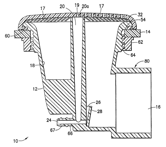
As shown in Figs. 1-2, the dry suction fitting assernbly 10
features a suction body 12 for arranging in relation to a wall 14
of the spa, whirlpool bathtub or other suitable water tub (not
shown), having a socket or suction inlet 16 for coupling to the
pump (not shown), and having an internal surface 18 with an
equilibrium tube 20 arranged therein with three openings 20a, 24,
26, including a first opening 20a that acts as a water flow
inlet, a second opening 24 that is open to the atmosphere via a
connection hose or other suitable connection device (for example,
see element 68 in Fig. 7) and that is filled with water during
normal operation, and a third opening 26 that is a safety orifice
coupled to the suction inlet 16. During normal operation, water
flows from the first opening 20a, through the equilibriurn tube
20, and out the third opening 26. In comparison, during a
blockage when water stops flowing through the suction body 12 to
the suction inlet 16 and water pressure decreases, water in the
equilibrium tube 20 evacuates out the third opening 26, and air
is drawn from the atmosphere through the second opening 24 and
out the third opening 26, causing the pump (not shown) to
6
CA 02590897 2007-05-22
WO 2006/047381 PCT/US2005/038117
cavitate so the blockage (not shown) may be r-emoved.
The internal surface 18 has a conical member 28 arranged in
relation to the third opening 26 that allows a high pressure at
the third opening 26 to prevent premature air- flow through the
third opening 26 during normal operation. The conical member 28
has about a 10 degree slope to prevent water retention in the
equilibrium tube 20, although embodiments are envisioned using
slopes having different degrees. As shown, the internal surface
18 has a conical shape that allows water to drain by gravity once
the water has left the main pipe area of the suction body 12, for
example, when the water in the spa, whirlpool bathtub or other
suitable water tub is drained. However, the scope of the
invention is intended to include the internal surface 18 having
other shapes to achieve the desired draining functionality.
The dry suction fitting assembly 10 includes a tube or hose
68 (see Fig. 7) coupled to the second opening 24 whose opposite
end is above the maximum water level . By way of example, the
tube 68 may be arranged inside the housing of the spa, whirlpool
bathtub or other suitable water tub and affixed so that its
opposing end (end not coupled to the opening 24) is arranged
above the water level of the spa, whirlpool bathtub or other
suitable water tub.
The dry suction fitting assembly 10 may also have a suction
cover 32 shown in Figs 1-3 arranged on an ann-ular rim 42 of the
CA 02590897 2007-05-22
WO 2006/047381 PCT/US2005/038117
suction body 12. The suction cover 32 has a multiplicity of
holes, openings or orifices 17 for allowing water to pass into
the suction body 12. The suction cover 32 may also incl-ude an
internal groove 34 (see Fig. 3) for coupling to an annu 1ar rim
20b (see Fig. 3) of the equilibrium tube 20. The suction cover
32 may be made of acrylonitrile-butadiene-styrene (ABS), although
the scope of the invention is not intended to be limited to any
particular type or kind of material. For example, embodiments
are envisioned using other materials either now known or later
developed in the future, including any of a class of plastics
based on ABS copolymers. The dry suction fitting assemb:Ly 10 may
also include one or more fasteners 36, each for passing through a
respective opening 38 (Fig. 3) in the suction cover 32 and into a
corresponding opening 40 (Fig. 4) in the annular rim 42 of the
suction body 12, for coupling the suction cover 32 to the suction
body 12. The fasteners 36 may take the form of one or rnore
stainless steel screws, although the scope of the invent ion is
not intended to be limited to any particular type or kind of
fastener or the material from which the fastener is made.
As shown in Fig. 5, the suction cover 32 may include one or
more male alignment members 50, each for coupling to a respective
female alignment member 52 in the annular rim 42 of the suction
body 12 for orienting the suction cover 32 in relation to-the
suction body 12.
8
CA 02590897 2007-05-22
WO 2006/047381 PCT/US2005/038117
As best shown in Figs. 1, 2, 5 and 6, the suction body 12
may also include one or more annular rims 54 for seating the
suction body 12 in relation to the wall 14 of the spa, whirlpool
bathtub or other suitable water tub (not shown) , as well as an 0-
ring 58 or other suitable gasket for arranging be:tween an annular
rim or groove 60 of the suction body 12 and the vvall 14 of the
spa, whirlpool bathtub or other suitable water tub. The dry
suction fitting assembly 10 also includes a nut c>r other suitable
fastening device 62 for cooperating with threads or other
suitable retaining member 64 of the suction body 12 for coupling
the suction body 12 to the wall 14 of the spa, wlairlpool bathtub
or other suitable water tub (not shown) . The nut 62 may be made
of PVC, although the scope of the invention is not intended to be
limited to any particular type or=kind of materia 1. For example,
embodiments are envisioned using other materials either now known
or later developed in the future, including any cf a class of PVC
copolymers. The suction body 12 also has a barb 66 forming the
second opening 24 and adapted for receiving the t ube 68 (Fig. 7)
thereto. The barb 66 also has ribs 67 for stretching and
gripping the tube 68 when it is affixed on the ba rb 66. As best
shown in Figs. 6c and 7, the suction body 12 also has one or more
hose retaining member 70, that may take the form of knife-like
teeth, arranged in relation to the barb 66 for fr-ictionally
engaging the tube 68 and preventing the same frorn pulling away
9
CA 02590897 2007-05-22
WO 2006/047381 PCT/US2005/038117
from the barb 66, as best shown in the assembly 10' shown in Fig.
7. The suction body 12 also has a barb protecting rnember 72
arranged in relation to the barb 66 for protecting the same.
As shown in Fig. 1, the axis of the internal surface is
arranged perpendicular to the axis of the suction dnlet so as to
form an L-shaped suction body generally indicated as 80.
By way of example, the 0-ring may be made of Buna N, EPDM or
Viton, and the suction body may be made of polyvinylchloride
(PVC), although embodiments are envisioned using other types and
kinds of materials.
As shown in Figure 6d, the annular rim 60 of the suction
body 12 has one or more 0-ring retainer ribs 82 for preventing
the 0-ring 58 from falling off during installation_ In Fig. 6b,
the suction body 12 is shown to include a rib 92 shaped to allow
for water drainage.
When assembled, the suction cover 32 is attached to the
elbow 80 with the screws 36 through the holes 38 into the holes
40. See Figures 2-4. The pressure equilibrium tube 20 is
aligned with the cover 32 by means of the groove 34. The o-ring
58 is placed in the groove 60. The elbow 80 with the cover 32
assembly is inserted through a hole generally indicated as 90
(Fig. 2) in the tub or spa wall 14. The assembly 10 is attached
to the tub or spa wall 14 by a nut 62. The present invention
overcomes the water retention problem by incorporat ing the
CA 02590897 2007-05-22
WO 2006/047381 PCT/US2005/038117
conical shape for the internal flow surface 18 once the water has
left the main pipe area so that all the wat--er will drain by
gravity. The fitting or assembly 10 may bc inclined up to about
degrees before having horizontal surface s that will retain
5 standing water. This allows for complete drainage. The cover 32
has numerous orifices 17 allowing water to pass through. The
conical feature 28 has about a 10 degrees s lope to prevent water
retention in the pressure equilibrium tube 20. Under normal
operation the pump (not shown) pulls water through one or more
10 suction devices or assemblies 10 in the spc-:::i, whirlpool bathtub or
other suitable water tub (not shown) . The water enters the
suction fitting or assembly 10 through the many orifices 17 and
continues through a pipe (not shown) typicaally cemented to the
socket 16 to the pump (not shown). The watrer is then discharged
through the pump and re-enters the tub or --:~pa (not shown) through
jets or other devices (not shown) thus creating a water cycle.
Water also enters the equilibrium tube 20 t/hrough one or more
holes 19. One end of a length of flexible tubing is connected to
the equilibrium tube 20,,while the opposite end is connected such
that it is always above the maximum water 3 evel. At any given
flow up to the maximum allowable flow rate. a pressure
equilibrium is created in tube 20 such that/ the pump (not shown)
is incapable of drawing air through the tulDe 68 (see Fig. 7)
connected to the inlet 24 whose opposite end is above the maximum
11
CA 02590897 2007-05-22
WO 2006/047381 PCT/US2005/038117
water level , as discussed above. When the suction cover 32 is
blocked, the flow rate will approach zero within a few seconds,
the vacuum pressure approaches 29.9 inches Hg, water is drawn out
of tube 20 and inlet 24, through opening 26 an.d into the pipe
connected to the pump and socket 16. Air is pulled in after the
water evacuates the tube 20 and inlet 24. The air cavitates the
pump (not shown) reducing the vacuum pressure to 0 inches Hg
within a few seconds. The object that is blocking the suction
cover 32 may then be easily removed. The quick drop in vacuum
force prevents hair entanglement, which may scriously harm a user
of the spa or hot tub. Experiments have showrn that a pump vacuum
pressure of about 22 inches Hg can be reached with no air being
drawn through the second opening until the uni..t is obstructed.
Finally, the other tubing material in the dry suction
fitting assembly 10 may be made of PVC or other suitable
material, although the scope of the invention is not intended to
be limited to any particular type or kind of material. For
example, embodiments are envisioned using other materials either
now known or later developed in the future, ix-icluding any of a
class of PVC copolymers.
The Scope of the Inventiori
It should be understood that, unless stated otherwise
herein, any of the features, characteristics, alternatives or
12
CA 02590897 2007-05-22
WO 2006/047381 PCT/US2005/038117
modifications described regarding a particular embodiment herein
may also be applied, used, or incorporated with any other
embodiment described herein.
Although the invention has been descri.bed and illustrated
with respect to exemplary embodiments thereof, the foregoing and
various other additions and omissions may be made therein without
departing from the spirit and scope of the present invention.
1:3