Note: Descriptions are shown in the official language in which they were submitted.
CA 02590994 2007-06-07
THERMO PUMP SUPPORT
FIELD OF THE INVENTION
The present invention relates to supports and more particularly, relates to a
triangular
support.
BACKGROUND OF THE INVENTION
Supports are used for many different objects and different types of supports
are
customized for the particular application for which it is intended. The use of
supports
having a triangular configuration is well known as the forces are engineered
such that they
generally support a load and transfer the load force to a vertical member
which is secured to
a substrate. One particular use for such support is in mounting thermo devices
such as
thermo pumps, air conditioners, heaters, and the like.
SUMMARY OF THE INVENTION
It is an object of the present invention to provide a triangular support which
can be
shipped in a knock down condition and be easily assembled using a minimum of
tools.
BRIEF DESCRIPTION OF THE DRAWINGS
Having thus generally described the invention, reference will be made to the
accompanying drawings illustrating an embodiment thereof, in which:
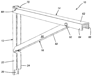
Figure 1 is a perspective view of a triangular support according to one
embodiment of
the present invention;
Figure 2 is a side elevational view thereof;
Figure 3 is a front elevational view thereof,
Figure 4A is a side elevational view showing securement of the top horizontal
member and diagonal brace;
-1-
CA 02590994 2007-06-07
Figure 4B is a view similar to Figure 4A; and
Figure 4C is a view showing the ends of the horizontal and diagonal brace
being in an
assembled position with respect to the vertical member.
DETAILED DESCRIPTION OF THE INVENTION
Referring to the drawings in greater detail and by reference characters
thereto, there
is illustrated in Figures 1 to 3 a triangular support generally designated by
reference
numeral 10.
Triangular support 10 has a vertical member 12 which is designed to be secured
to a
substrate; a horizontal member 14 which will support a load; and a diagonal
brace 16.
Vertical member 12 has a back wall 20, a first side wall 22 and a second side
wall 24.
Vertical member 12 is symmetrical about a vertical axis and thus, only
reference will be
made to side wall 22, being understood that side wall 24 has a like
configuration. Where
appropriate, similar reference numerals with a prime are employed for side
wall 24.
At its upper end, side wall 22 has an upper tab 26 and a side tab 28. A notch
30 is
provided at the juncture of upper tab 26 and side tab 28.
A recess generally designated by reference numeral 32 is formed at the upper
end
wall of side wall 22. Recess 32 is defined by a plurality of wall segments as
follows.
A first horizontal wall segment 34 forms the upper edge of upper tab 26. A
first
vertical wall segment 36 is formed to extend downwardly from upper tab 26 with
an arcuate
segment 40 being contiguous therein.
Situated lower down on vertical member 12 and being designed to receive an end
of
diagonal brace 16 is a second recess 44. Recess 44 is defined by a bottom
upwardly
extending diagonal wall 46 and a downwardly extending diagonal wall 48. The
upper
-2-
CA 02590994 2007-06-07
portion of recess 44 is defined by a downwardly extending top diagonal wall 50
and an
upwardly extending diagonal wall 52. A notch 54 is formed adjacent to wall 52.
At its
inward extremity, recess 44 has an arcuate wall 60.
Horizontal member 14 has a back wall 62, and first and second side walls 64
and 66
respectively. At one end thereof, there are provided a pair of cut outs 68 and
70 which are
formed at the joinder of back wall 62 with a respective side wal164, 66.
Apertures are
located in side wa1164, 66 respectively.
Diagonal brace 16 also has a back wall 78 and a pair of side walls 80, 82. Cut
outs
84 and 86 are provided at the point of joinder of back wall 78 with side walls
80 and 82
respectively. A first aperture is provided in side wall 80 and a second
aperture in side
wall 82.
For assembly, vertical member 12 may be secured to a suitable substrate S by
any
suitable means (not shown). Subsequently, an end of horizontal member 14 is
inserted in a
diagonal manner into recess 32. The undercut arrangement permits the end walls
of
horizontal member 14 to rotate such that back wall 20 rests against horizontal
segment 34
and with tabs 26, 26' fitting within cut outs 68 and 70. The position is that
shown in
Figures 4B and 4C.
Subsequently, as shown in Figure 4A, end of diagonal brace 16 is inserted into
recess 44 and brace 16 pivoted upwardly as shown in Figure 4B. In this
sequence, the
extended portion formed by top diagonal walls 50 and 52 extends through cut
out 68.
Subsequently, a nut 90 and bolt 92 will pass through the apertures in side
walls 64, 66, 80
and 82 to secure the diagonal brace in position.
It will be understood that the above described embodiment is for purposes of
-3-
CA 02590994 2007-06-07
illustration only and that changes and modifications may be made thereto
without
departing from the spirit and scope of the invention.
-4-
