Note: Descriptions are shown in the official language in which they were submitted.
CA 02591108 2007-06-08
THEFT DETERRENT SYSTEM HOOK
BACKGROUND OF THE INVENTION
1. Field of the Invention
The invention relates generally to theft deterrent devices for dispensing
products. More specifically, the invention relates to dispensing devices that
incorporate theft deterrent measures, such as knobs and time delays.
2. General Background
Theft of small items in retail stores is an all too common problem.
Items that are in high demand by thieves include over-the-counter (OTC)
products such as analgesics and cough and cold medications, razor blades,
camera film, batteries, videos, DVDs, smoking cessation products and infant
formula. Shelf sweeping is a particular problem for small items. It occurs
when someone removes all the shelf stock (and in some instances, removes
the hook on which the merchandise is hanging), and exits the store, similar to
a "smash and grab" shoplifting technique. Shelf sweeping relies on excessive
quantities of product being available on the shelf. However, retailers need to
keep substantial inventory on shelf or incur the cost of constantly
restocking.
In addition to preventing theft, retail stores may want to limit the
purchase of certain items. For example, to make methamphetamine, large
quantities of cold medication are needed. Pseudoephedrine, the sole active
ingredient in many cold medicines and decongestants, is also a key ingredient
in methamphetamine, a powerful and highly addictive stimulant.
1
CA 02591108 2007-06-08
Retailers are constantly challenged to balance the needs of legitimate
consumers' access to high theft items with measures to minimize the
incidence of theft. It has long been known to place items such as cigarettes,
sodas and newspapers in vending machines. Such machines require
complete self-service by the customer. The customer places money into the
vending machine and the machine dispenses the desired item. However,
vending machines may be inconsistent with the way that people currently
purchase items; many people prefer to use credit or debit cards instead of
cash. Vending machines may also be inconvenience and occupy a great deal
of space. Finally, typical vending machines do not employ any time delay
mechanism to prevent a purchaser from quickly dispensing all the items in the
vending machine.
Because theft has become so rampant in certain product categories,
such as razors, infant formula, and cold medicine, many retail stores are
taking the products off the shelves and placing them behind the counter or
under lock-and-key. Customers must request the products in order to make a
purchase. This requires additional labor costs to provide individual service
to
customers who would normally not require it. It also makes it difficult for
customers to compare products. Furthermore, it may be impossible where
the space behind the counter is limited and is needed for prescription
medications. In some cases, some products are simply unavailable due to
high pilferage rates.
Therefore, a device or dispensing apparatus that minimizes the
incidence of product theft, particularly sweeping, is needed. The device or
2
CA 02591108 2007-06-08
dispensing apparatus should also be able to fit within common grocery, drug
store or other retail environment shelves. It is also desirable that the
device
or dispensing apparatus effectively display the products so consumers can
easily identify the products. It is also preferable that the dispensing
apparatus
be easy to use.
Additionally, studies have shown that in addition to preventing
sweeping, another desirable form of theft deterrence is to cause a time delay
between the dispensing of multiple products. Would-be thieves are less likely
to steal products if there is a substantial delay between the dispensing of
individual products. It is also desirable to achieve time delayed dispensing
of
products in a cost effective manner.
BRIEF SUMMARY OF THE INVENTION
In certain embodiments of the invention, the apparatus for dispensing
products includes a theft deterrent retail product-dispensing hook. In certain
embodiments, the hook prevents product "sweeping" (where a thief quickly
empties a conventional retail hook of product) and also delivers a time-
delayed delivery of product per hook.
For example, a specific embodiment of a time-delay display hook
system, comprises a two-prong system having an upper member and a lower
member, the upper member adapted to support a dispensing system and the
lower member adapted to support product to be dispensed; a dispensing
system associated with the upper member that comprises a motor, a blocking
member, and an activation member, wherein the activation member is
adapted to be triggered to release a product to be dispensed from the lower
3
CA 02591108 2007-06-08
member. Upon triggering of the activation member, the blocking member is
activated to prevent further product from being dispensed and the motor is
activated to prevent further turning of the activation member until the motor
times out, providing a time-delay between dispending of individual products.
According to an aspect of the present invention, there is provided a
time-delay display hook system, comprising:
(a) a two-prong system having an upper member and a lower
member, the upper member adapted to support a dispensing system and the
lower member adapted to support product to be dispensed;
(b) a dispensing system associated with the upper member, the
dispensing system comprising a motor, a blocking member, and an activation
member,
wherein the activation member is adapted to be triggered to release a
product to be dispensed from the lower member, wherein upon triggering of
the activation member (i) the blocking member is activated to prevent further
product from being dispensed and (ii) the motor is activated to prevent
further
turning of the activation member until the motor times out, providing a time-
delay between dispending of individual products.
BRIEF DESCRIPTION OF THE DRAWINGS
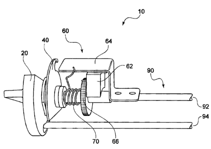
FIG. 1 shows a side perspective view of one embodiment of a theft
deterrent hook system.
FIG. 2 shows an exemplary mounting system and a two-prong for a
theft deterrent hook system.
4
CA 02591108 2007-06-08
FIGS. 3A and 3B show one embodiment of an activation member or
knob for a theft deterrent hook system.
FIG. 4 shows one embodiment of a blocking member for a theft
deterrent hook system.
FIG. 5 shows an exploded perspective view of an alternate
embodiment of a theft deterrent system.
FIG. 6 shows the system of FIG. 5 in a partially assembled position,
with the activation member being put into place.
DETAILED DESCRIPTION
As shown in FIG. 1 and described in more detail below, embodiments
of the invention provide a two-prong system with a dispensing system on the
upper member of the hook. The dispensing system is a spring-loaded rotary
gate system, actuated by a customer turning an activation member or a knob,
allowing one gate (which may be a part of knob or a separate element) to
permit the forward-most product to be vended while the second gate (which
may be a blocking member) prevents a subsequent product from being
vended until the spring-loaded timing device re-sets itself.
Thus, the time-delay of the dispensing system provides a theft
deterrent feature. In addition to the product-dispensing aspect of the device,
there is provided a key/lock provision on the activation member or knob that
allows a retailer to re-position the forward gate (activation member or knob)
and allow product to be loaded on to the hook by a retail attendant and then
locked in the position that allows for vending. The key/lock may also be used
to completely lock the device during high theft times.
5
CA 02591108 2007-06-08
First, as shown in FIG, 2, there is provided a two-prong system 90.
Hook 90 includes an upper member 92 and a lower member 94. Members
may be attached to a mounting member 96, which may in turn, mount
member to a display board, a cross bar 98, or any other structure. If
provided,
cross-bar 98 may be attached to an in-store shelf backing by a hanger 100 or
any other appropriate attachment mechanism. One advantage of a cross-bar
mounting system is that it allows adjustability to the left to right. Another
advantage is that it ensures that the connection of the hook 90 to the cross-
bar 98 is sound. Present devices rely on pegboard backer which can easily
be broken. Another advantage is that incorporating a mounting member 96 to
the hook can help connect the hook to a pre-existing in-store retail fixture.
Additionally, mounting systems according to various embodiments help impart
strength and lower the risk of would-be-thieves from easily removing the
system from a shelf. (An additional built-in theft deterring mechanism is a
time delay between the dispensing of products, discussed below.) This
system may be constructed of tubular steel or any other conventional
materials.
The embodiment of theft-deterring device 10 shown in FIG. 1 includes
a two-prong system 90 associated with a dispensing system 60. The
dispensing system 60 may be associated with the upper member 92, so that
the lower member 94 can support product to be dispensed. Dispensing
system 60 is a spring-loaded rotary gate system that allocates only one
product at a time, with a time delay between each product dispensing action.
6
CA 02591108 2007-06-08
Each of these elements will be discussed in more detail below, but in a
specific embodiment, the dispensing system 60 is actuated by the activation
of an activation member 20 (which may a knob, a lever, a push button, a pull
button, or any other device that may be used to activate a motor), which
releases the lower member 94 from the knob 20 and allows a single product
to be removed. That motion also rotates a blocking disc 40 or gate that
prevents all other products on the member from being removed. The turning
motion also loads a spring 70 that will begin to rotate and actuate a motor 62
once the activation member 20 (which is shown as a knob in the figures) is
released. As the spring-loaded system begins to unwind (guided by a gear
and resistance motor), there is a point at which the blocking disc 40 will
allow
another product to gravity feed forward to a position between the blocking
disc
40 and the activation member 20. This product, and only this product, is in a
position to be accessed by another rotation of the activation member 20.
Turning now to the other specific components of the system, one
embodiment of activation member 20 is shown in FIGS. 3A and 3B as a knob
20. FIG. 3A shows the side of knob 20 that faces consumer, which has a
portion 22 to be grasped. As shown in FIG. 3B, knob 20 also has a
dispensing groove 24, which generally follows at least a portion of
circumference 26 of knob 20. In use, dispensing groove 24 releases the end
of lower member 94, which allows the consumer to remove the product. Knob
20 also has a connecting member 28, which allows it to be connected to
upper member 92 and/or the spring-loaded system 60. Connecting member
28 is shown as a circular opening, but it should be understood that any
7
CA 02591108 2007-06-08
connection mechanism of any shape and size that will allow knob to connect
to the rest of device 10 (e.g., a peg, a ratcheted system, etc.) is considered
within the scope of this invention.
Once knob 20 is turned, blocking member 40 moves into a position that
blocks product from sliding down member 94. As shown in FIG. 4, blocking
member 40 has a shape similar to the shape of knob 20. Its groove 42 moves
to the position to release product only after the motor has timed out. In one
embodiment, the motor action may slowly rotate blocking portion 44 around in
order to allow groove 42 to release product once motor has timed out. In
another embodiment, blocking portion 44 remains stationary during the motor
action, and the groove 42 snaps back into place once the motor times out,
allowing product to gravity feed.
Knob 20 and blocking member 40 are attached to a spring/motor
combination. As shown in FIG. 1, one end of spring 70 is preferably attached
to the motor mount 62 (which provides resistance for spring's action) and the
other end is attached to a resistance motor 62 and gear 66 system. The
turning of knob 20 tightens and loads spring 70, while the motor and gear
system are allowed to freewheel. Once the knob 20 is released, the spring
tension activates motor 62. In a certain embodiment, the motor 62 is of the
type commonly used in toy cars, so that is can be wound up and then un-
wound to create energy or movement. The resistance motor 62 may
incorporate a series of gears 66 which prevent the blocking member 40 and
knob 20 from returning to the dispensing mode until a period of time has
passed, such as approximately 15 or 30 seconds. thus, one advantage of the
8
CA 02591108 2007-06-08
devices described is that in addition to preventing sweeping of multiple
products do to the single item dispending, they also provide a time-delay in
between each dispensing step. This time delay may be any desired time, for
example from 5 to about 60 seconds. (Much longer may prevent legitimate
consumers from purchasing product, although any time limit is possible.)
As the spring loaded dispensing system 60 begins to unwind, there
becomes a point at which the blocking member allows a product to gravity fed
forward to a position in between the blocking member 40 and the knob 20.
This is the only product that is allowed to move forward to the staging
position
to be accessed by another rotation of the knob 20.
FIG. 5 shows an exploded perspective view of an alternate
embodiment of device 10. This embodiment includes activation member 20,
blocking member 40, spring 70, motor 62, and gear 66. It also features a
motor mount 64, which covers motor 62, prevents contaminants from entering
the dispensing system 60, and gives the device 10 a more polished look. This
embodiment also has a dispensing bar system 120 that can hold and support
product, if desired. The system 120 includes a support bar 122 and a support
pusher 124. In addition to providing a supportive back for product, support
pusher 124 is spring loaded and helps to push product forward. In one
embodiment, upper member 92 has a spring-coiled member 91 on its
underneath portion and support pusher 124 has an engaging system 126 that
cooperates with upper member 92. The engaging system 126 may feature
outer arms 128 that are adapted to receive ends 93 of upper member 92.
Engaging system 126 may also have an inner track 129 track that engages
9
CA 02591108 2007-06-08
with a presses against a spring coiled-member 91 on the underneath side of
upper member 92. As product is allowed to move forward due to the action of
the motor, spring coiled-member 91 forces support pusher 124 forward.
Support pusher 124 also has an opening 125 that receives lower member 94
in use. Support pusher is particularly useful is systems that are not gravity
feed systems, although gravity feed systems may also use the theft deterrent
hook features described herein.
Also, in this embodiment, rather than being a circular rod, upper
member 92 is shown as a flat bar 112. Flat bar 112 may be integrally
connected to a mounting member or it may be formed as a separate piece,
depending upon display requirements. As shown in FIGS. 5 and 6, flat bar
112 may have an opening 114 that receives lower member 94, which may
hold the elements more securely and conveniently together.
Another beneficial feature of device 10 is that support bar 122 may be
adjusted to receive variously-sized product. As shown in FIG. 5, a support
member 140 may be provided that can be mounted onto flat bar 122. Support
member 140 has adjustable openings on its underneath side that allow
prongs 123 of support bar 122 to be received at different locations to provide
more or less space for product in the area between support pusher 124 and
support bar 122. (This can be seen more clearly on FIG. 6.)
A further feature of device 10 is that dispensing system 60 may be
removed from the two-prong system 90 for restocking purposes. Once
assembled, dispensing system 60 may be a self-contained unit having the
activation member (shown as a knob) and motor connected to one another.
CA 02591108 2007-06-08
The system 60 can have a key lock 150 that allows system 60 to removed
from and replaced onto two-prong system 90. Dispensing system 60 can also
be completely locked during busy, high-theft times.
Alternatively, the key lock 150 may be associated with knob 20 to
allows a retailer to re-position the forward gate (turning knob) and allow
product to be loaded onto the hook by a retail attendant and then locked in
the
position that allows for vending.
During use of the system shown in FIGS. 5 and 6, when the consumer
turns knob 20, a single product is released from lower member 92, and the
groove 42 of blocking member engages lower member 92 to prevent further
product from being released. The turning of knob 20 also winds the motor,
which controls the movement of blocking member 40. As discussed above,
blocking member 40 may be slowly rotated by the movement of motor (so that
once motor times out, blocking member allows another product to be
released), or blocking member 40 may remain in a blocked position and then
be released in a single, snapping motion once motor times out or reaches a
pre-determined point in its progress.
While a preferred embodiment of the invention has been described, it
should be understood that alternate versions may be developed that would fall
with in the scope and sprit of the attached claims. For example, it may be
possible to use two gates, rather than a knob and a blocking member. The
gates could retain products when in the closed position and may be opened
by activating a push-button or lever. The spring loaded motor could still be
engaged by a spring, although it could also be operated by a circuit board, an
11
CA 02591108 2007-06-08
electric motor, or any other appropriate device. In this instance, when a
consumer presses a dispensing button or activates a dispensing lever, an
electric motor could cycle, opening a first gate, allowing a product to be
removed, but activating a second gate to prevent more than one product from
being dispensed. Once the product has been removed, the spring can snap
back to its original position and pushes the gates closed. In the snap-back
embodiment, there may be provided a trigger 152 that snaps and locks when
the activation member 20 is turned. When the motor unwinds, it pulls the
trigger 152 out from its locked position. Additionally, the time delay may be
controlled by a circuit board or a built-in timer, rather than the motor and
spring concept.
To further deter theft, device 10 may include a sound to alert store
employees that a product is being dispensed. For example, device may
include a clicker for providing an audible clicking sound. The clicker may be
incorporated into the spring 70 so that the sound is heard when the spring is
recoiled when the knob, button or lever is triggered. Additionally or
alternatively, device 10 may include an audible beeping sound or an audible
message when a product is dispensed. These sounds may alerts people in
the vicinity that a product is in the position to be removed, attracting the
attention of a store clerk and deterring thieves.
While the invention has been described in detail with particular
reference to the disclosed embodiments, it will be understood that variations
and modifications can be affected within the spirit and scope of the invention
as described herein.
12