Note: Descriptions are shown in the official language in which they were submitted.
CA 02591263 2009-06-11
1
POST IN POST PRODUCT PACKAGING AND DISPLAY STRUCTURE
BACKGROUND
Field Of The Invention
This patent relates to the packaging arts. More
particularly, this patent relates to a post in post type
packaging and display system wherein outer posts are
attached to each other by short inner post segments.
Description of the Related Art
Retailers such as mass merchandisers sometimes display
their products in the same packaging that the products were
shipped in from the vendors. One form of such packaging
comprises vertically arranged trays held apart by support
posts.
Sonoco Development, Inc., the assignee of the present
invention, has developed a proprietary post in post system
for the packaging, shipping and displaying of products in
a mass merchandising or general retail environment. The
system, described in United States Patent No. 7,066,342,
comprises a plurality of vertically spaced corrugated
trays for holding the products, tubular outer support
posts that support the trays and space them apart, and
inner guide posts that key inside the support posts
(thus "post in post") to lock the system together and
provide axial compression strength. The tray and post
structure may be carried on a standard pallet and wrapped
in an outer wrap to protect the products from dust
CA 02591263 2007-06-19
WO 2006/078478 PCT/US2006/000543
2
and damage during shipment.
Each corrugated tray has die-cut openings large enough
to accommodate the inner guide posts but smaller than the
outer support posts. To assemble the system, the inner
guide posts may be inserted through the tray openings and
the outer support posts slipped over the inner guide posts.
The outer support posts evenly space apart the trays and
provide a platform for the tray above.
In the original design, the sum of the lengths of the
inner guide posts is substantially the same as the sum of
the lengths of the outer support posts. In other words,
both the inner guide posts and outer support posts extend
substantially the entire height of the system, providing a
double post support frame. This configuration can be an
unnecessary use of post material if the outer support posts
themselves are strong enough to support the system.
It is therefore an object of the present invention to
provide a post in post packaging and display system in which
the inner guide posts are substantially shorter then the
outer guide posts.
Another object of the invention is to provide a post in
post packaging and display system in which the inner guide
posts are attached to the insides of the outer guide posts.
Further and additional objects will appear from the
description, accompanying drawings, and appended claims.
CA 02591263 2009-06-11
3
SUMMARY OF THE INVENTION
The present invention is a post in post structure for
shipping products and displaying them in a retail
environment. The structure comprises a pair of vertically
aligned outer posts having hollow interiors and a short
inner post segment inserted within the hollow interiors of
the outer posts and affixed to both outer posts. Preferably
the outer posts are in end to end contact. The inner posts
need only be long enough to enable each pair of adjacent
outer posts to be adequately secured to each other.
In a further embodiment, the post in post structure
also comprises a tray having at least one opening therein,
wherein an inner post segment is inserted partway through
the opening and two outer support posts are attached to
either end of the inner post segment.
The invention is particularly suitable for use with the
post in post packaging and display system described in
United States Patent No. 7,066,342. That system comprises
vertically spaced apart trays, inner posts inserted through
openings in the trays, and hollow outer posts slipped over
the inner posts. The posts space the trays apart and lock
them together in vertical alignment.
CA 02591263 2007-06-19
WO 2006/078478 PCT/US2006/000543
4
THE DRAWINGS
Figure 1 is a perspective view of the post in post
structure of the present invention.
Figure 2 is an exploded view of the post in post
structure of Figure 1.
Figure 3 is a perspective view of a packaging and
display assembly incorporating the post in post structure of
Figure 1.
Figure 4 is an exploded view of the packaging and
display assembly Figure 3.
Figure 5 is a perspective view of two corrugated blanks
used to make a corrugated inner post segment and a
corrugated outer post.
Figure 6 is a perspective view of the corrugated blanks
of Figure 5 shown partially assembled.
Figure 7 is a perspective view of a corrugated inner
post segment and a corrugated outer post.
Figure 8 is a top view of a corrugated inner post
segment and a corrugated outer post.
Figure 9 is an exploded view of an alternative
embodiment of a post in post structure according to the
invention.
CA 02591263 2009-06-11
DETAILED DESCRIPTION OF THE INVENTION
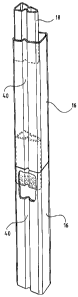
As shown in Figures 1 and 2, the present invention is a
post in post structure comprising a pair of vertically
aligned outer posts 16 having hollow interiors and a short
5 inner post segment 18 inserted within the hollow interiors
of the outer posts 16, the inner post segment 18 being
affixed to both outer posts 16. The inner post segment 18
may be affixed to the outer posts 16 by glue, adhesive,
staples, friction fit or any other suitable means. The posts
may also be connected by mechanical means. For example, as
shown in Figure 9, D-shaped tabs 26 formed in the inner post
segment 18 can be inserted into slots 28 formed in the outer
posts 16 to connect the posts together. Preferably the outer
posts 16 are in end to end contact.
In a further embodiment, the structure also comprises
at least one tray 12 having at least one opening 24 in the
bottom 36 of the tray 12, wherein one of the outer posts 16
is aligned over the opening 24 and the other outer post 16
is aligned under the opening 24 such that their hollow
interiors communicate with the opening 24. The inner post
segment 18 is inserted inside the outer posts 16 and through
the tray opening 24 and is affixed to the outer posts 16 as
before.
The invention is particularly suitable for use with
the post in post packaging, shipping and display assembly
described in United States Patent No. 7,066,342. As shown
in Figures 3 and 4, the packaging and display assembly 10
CA 02591263 2009-06-11
6
comprises vertically spaced trays 12 for holding products
(e.g. snack food containers), hollow outer posts 16 arranged
over openings 24 die-cut into the bottom 36 of each product
tray 12, and inner post segments 18 keyed (inserted) inside
the outer posts 16 and through the tray openings 24 to lock
the system together. The outer posts 16 provide a platform
for each tray 12 and evenly space the trays 12 apart.
Unlike the post in post system described in United
States Patent No. 7,066,342, the inner post segments 18 are
not at least as long as the outer posts 16 and they are not
placed end to end. Rather, the inner post segments 18 are
substantially shorter than the outer posts 16 and they are
spaced apart. The inner posts segments 18 need only be long
enough to enable each pair of adjacent outer posts 16 to be
adequately secured to each other.
The product trays 12 preferably are formed from
corrugated board, although any suitable material may be
used. Each tray 12 comprises a bottom panel 36 and short
sidewalls 38 extending upward from the periphery of the
bottom panel 36. The bottom panel 36 and/or side panels 38
may be printed or otherwise decorated in any desirable
fashion to increase the aesthetic appeal of the display.
The bottom panel 36 has die-cut openings 24 disposed
in void spaces around the product containers 14. These
openings 24 are large enough to accommodate the inner post
segments 18 but smaller than the outer posts 16 or at least
configured such that the outer posts 16 cannot fit within
the openings 24. The number of openings 24 required in each
CA 02591263 2009-06-11
7
tray 12 is a function of the number of post columns. As
shown in Figures 3 and 4, a typical assembly 10 will have
four columns of posts and thus four openings 24 in each tray
12. The die-cut openings 24 may be arranged on the trays 12
in any suitable fashion, although it is preferred that there
be an opening 24 near each corner of the trays 12.
The height of the outer posts 16 is determined by the
height of the product containers or, more particularly, the
desired spacing between trays 12. The outer posts 16 may be
attached to the trays 12 in some fashion or simply held in
place by the inner post segments 18.
Preferably, the outer posts 16 are hollow paper tubes
formed into a desired shape, such as those manufactured by
Sonoco Products Company of Hartsville, South Carolina and
described in U.S. Patent Nos. 4,482,054; 5,593,039;
6,059,104 and 6,186,329. In the embodiment illustrated
in the figures, the outer posts 16 have a substantially
rectangular cross-sectional profile with beads or grooves 40
running longitudinally along two opposing walls, although
any suitable cross-sectional shape may be used, including
but not limited to circular and triangular. Since the outer
posts 16 are visible to the consumer, they too may be
printed or otherwise decorated in any desirable fashion to
increase the aesthetic appeal of the display.
The inner post segments 18 must be small enough in
cross-section to be inserted through the openings 24 in the
trays 12 and inside the ends of the outer posts 16. Like
CA 02591263 2009-06-11
8
the outer posts 16, the inner post segments 18 may be wound
paper tubes such as those manufactured by Sonoco Products
Company. The inner post segments 18 may have any suitable
cross-sectional shape, including but not limited to
triangular, and should fit snugly inside the outer posts 16.
Thus there has been described a post in post structure
for use in the packaging, shipping and displaying of
products. The structure features a pair of outer posts 16
connected together by a short inner post segment 18. The
inner post segment 18 is affixed to the outer posts 16 and
need only be long enough to enable the outer posts 16 to be
adequately secured to each other.
In one alternative embodiment of the invention, the
outer posts and inner post segments are made from folded
corrugated rather than wound paper tubes. As shown in
Figures 5-8, each post is formed from a corrugated blank 42,
44 that is folded into a cylinder having a polygonal cross
section. The corrugated inner post segments 44 are sized to
fit snugly within the corrugated outer posts 42 and, as in
the preferred embodiment, need only be long enough to secure
two outer posts 42 placed end to end.
Other modifications and alternative embodiments of the
invention are contemplated that do not depart from the scope
of the invention as defined by the foregoing teachings and
appended claims. It is intended that the claims cover all
such modifications that fall within their scope.