Note: Descriptions are shown in the official language in which they were submitted.
CA 02591353 2007-06-06
- 1 -
"A method for mounting an auxiliary member on a door or window
frame"
***
The present invention relates to accessories for door and
window frames and it pertains to a method for mounting an
auxiliary member on a door or window already installed.
A door or window comprises a frame and a drive assembly
constituted by the devices and components that enable to
transmit the opening/closing motion from the handle to various
closure elements. The devices and components of the drive
assembly are mounted, regulated and fastened to the frame when
installing the window or door.
In some cases, after the window or door is installed, it is
necessary to add an auxiliary member to the window or door. For
example, it can be necessary to add one or more additional
closure members to enhance the security of the closure.
In prior art solutions, the addition of auxiliary members in
a window or door already installed is a long and complex
operation, that entails cutting one or more transmission rods to
measure and forming holes on the rods for fastening the
auxiliary members. These operations require equipment available
in the workshops of the manufacturers but that is not easily
transportable on the site where the window or door is installed.
The object of the present invention is to provide a method
for mounting an auxiliary member on a window or door already
installed, that is simple and does not require the use of
special equipment.
According to the present invention, said object is achieved
by a method having the characteristics set out in claim 1.
The present invention shall now be described in detail with
reference to the accompanying drawings provided purely by way of
non limiting example, in which:
- figure 1 is a perspective view of a window or door whereon
an auxiliary member is to be mounted,
- figure 2 is a perspective view of the part designated by
CA 02591353 2007-06-06
- 2 -
the arrow II in figure 1,
- figure 3 is a section in enlarged scale according to the
line III-III of figure 2,
- figures 4 through 8 are perspective views showing the
sequence of the fastening operation between the auxiliary member
and a transmission rod,
- figures 4a and 5a are sections according to the lines IV-
IV and V-V of figures 4 and 5,
- figures 4b and 5b are enlarged details of the parts
indicated by the arrows IV and V in figures 4a and 5a,
- figures 6a, 7a and 8a are sections according to the lines
VIa - VIa, VIIa-VIIa and VIIIa-VIIIa of Figures 6, 7 and 8,
- figures 6b, 7b and 8b are sections according to the lines
VIb-VIb, VIIb-VIIb, VIIIb-VIII of Figures 6, 7 and 8, and
- figures 9 through 16 are perspective views showing the
mounting sequence of an auxiliary member on a window or door
whereon a drive assembly has already been previously mounted.
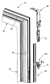
With reference to figure 1, the number 10 designates the
frame of a tilt-and-turn opening window. The frame 10 comprises
two vertical uprights 12 joined together by a lower cross member
14 and by an upper cross member 16. The uprights 12 and the
cross members 14, 16 are provided on their outer longitudinal
side with slots 18, 20 (figure 2) able to receive the components
of a drive assembly 22 that enables to select, by means of a
handle 31, a closed position, a turn opening position and a tilt
opening position.
The drive assembly 22 comprises a plurality of actuating
members 24, 25, 26, 27, 28, and a plurality of transmission rods
30, 32. The actuating members shown in figure 1 are,
respectively, a vertical fulcrum 24, a cremone bolt 25, an
angled transmission element 26, a cursor 27 and a scissors arm
28. The frame 10 is also provided with a control handle 31. The
general structure and the operation of the actuating members 24,
25, 26, 27, 28 are known in themselves and they are outside the
scope of the present invention.
CA 02591353 2007-06-06
- 3 -
The actuating members 24, 25, 26, 27, 28 are mounted on the
frame 10 as described in a contemporaneous patent application by
the same applicant with the title: "A method for mounting a
drive assembly for door and window frames".
With reference to figures 1 and 2, the number 130 designates
an auxiliary member to be mounted on the frame 10 after the
actuating members 24, 25, 26, 27, 28 have already been mounted
definitively on the frame 10.
The auxiliary member 130 is for example constituted by,a
closure member destined to co-operate with an abutment (not
shown) fastened to the fixed frame of the window or door. The
auxiliary member 130 is destined to be mounted on one of the
transmission rod 30, 32.
As shown in figures 4 and 4a, each transmission rod is
constituted by an extruded, drawn or profiled element having
constant cross section along its own longitudinal axis.
Each transmission rod 30, 32 comprises a central portion 34
and two lateral portions 36, 38 situated at opposite parts
relative to the central portion 34. The two lateral portions 36,
38 have respective mutually co-planar bases 40, 42. The central
portion 34 has a base 44 that is parallel and distanced from the
bases 40, 42 of the lateral portions 36, 38. The base 44 of the
central portion 34 is connected to the respective bases 40, 42
of the lateral portions 36, 38 by means of two longitudinal ribs
46. The base 44 of the central portion 34 and the ribs 46 form a
"U" shaped longitudinal groove 48 that extends along the central
portion 34 and that separates the two lateral portions 36, 38.
The central portion 34 has two lateral extensions 50 and 60 that
extend exteriorly beyond the ribs 46. The two bases 40, 42 of
the lateral portions 36, 38 have at their outer ends respective
longitudinal ribs 52, 54. The height of the rib 52 of the
lateral portion 36 is about half the height of the ribs 46. The
rib 54 of the lateral portion 38 ends at the same height as the
base 44 of the central portion 34 and it has a laterally
projecting edge 56.
CA 02591353 2007-06-06
- 4 -
The two lateral portions 36, 38 form respective channel-
shaped guides 58, 61. Each of the two guides 58, 61 has an upper
surface 62 and two lateral surfaces 64, 66. The central portion
34 has an upper surface 68 that is parallel to the upper
surfaces 62 of the guides 58, 61. The lateral extensions 50, 60
of the central portion 34 have lower surfaces 70 inclined at an
acute angle relative to the lateral surfaces 64 of the ribs 46.
The thickness of the bases 40, 42 of the lateral portions 36, 38
of the ribs 46 and of the base 44 of the central portion 34 is
substantially constant. The rods 30, 32 are preferably made of
metallic material (e.g., aluminium alloy) or plastic material
(e.g., polyamide).
With reference to figure 3, the auxiliary member 130 has a
coupling portion 72 for coupling with the transmission rod 30,
32. Similar coupling portions 72 are provided on each actuating
member 24, 25, 26, 27, 28. Each coupling portion 72 comprises a
body 74 wherefrom project two parallel longitudinal ribs 78, 80.
The ends of the longitudinal ribs 78, 80 are shaped in such a
way as to establish a sliding coupling in longitudinal direction
with the guides 58, 61 of the transmission rod 30, 32 and
fastened in any direction orthogonal to the direction of
sliding.
With reference to figure 3, the coupling portion 72 has a
flat lower surface 82 wherefrom extend the ribs 78, 80. The
lower ends of the ribs 78, 80 have respective coplanar flat
surfaces 84, parallel to the flat surface 82. When cross
sectioned, the longitudinal rib 78 has at its end an outer
lateral extension 86 and an inner lateral extension 88. The two
lateral extensions 86, 88 have respective lateral parallel walls
90, 92, orthogonal relative to the surfaces 82, 84. The inner
lateral extension 88 has an upper surface 94 inclined at an
acute angle relative to the lateral wall 92. The longitudinal
rib 80 has, in cross section, an inner lateral extension 96 with
a lateral wall 98 parallel to the wall 92 and an upper surface
100 inclined at an acute angle relative to the lateral wall 98.
CA 02591353 2007-06-06
- 5 -
The coupling portion 72 of the auxiliary member 130 has a
section 102 provided with a threaded through hole 104 with
orthogonal axis relative to the inner surface 82 of the body 74.
A screw 106 is engaged in the threaded hole 104. The screw 106
has a threaded body 108 and a tip 110 that projects from the
threaded body 108. The tip 110 has a cylindrical lateral wall
with a smaller diameter than the diameter of the threaded body
108. The tip ends with a flat wall orthogonal to the
longitudinal axis of the screw.
The screw 106 has a hexagonal slot 112 and an arresting edge
114 at one end of the threaded body 108. The length of the
threaded body 108 is substantially equal to the length of the
threaded hole 104, so that when the screw 106 is completely
screwed into the hole 104 the tip 110 projects from the lower
surface 82 of the body 74.
With reference to Figures 4, 4a and 4b, the coupling portion
72 of each auxiliary member 130, 30 couples in sliding fashion
on the transmission rod 30. At the time of the coupling between
the auxiliary member 130 and the transmission rod 30, the screw
106 is only partially screwed into the hole 104 and the front
end of the tip is recessed in the hole 104 relative to the lower
surface 82 of the coupling portion 72. The coupling portion 72
and the transmission rod 30 are therefore free to slide with
respect to one another in longitudinal direction. To allow
telescopic sliding between the two components, the respective
cross-sections are so dimensioned as to leave a constant play
along the entire cross-section, e.g. in the order of 0.1 mm, as
shown in particular in figures 4a and 4b.
Hereafter, the sequence will be described for the mounting
of the auxiliary member 130 starting from the configuration in
which the actuating members 24, 25, 26, 27 and 28 are already
mounted on the frame 10.
With reference to figure 9, the angled transmission element
26 is provided with a coupling portion 72 similar to the
coupling portion 72 of the auxiliary member 130 described above.
CA 02591353 2007-06-06
- 6 -
The coupling portion 72 is provided with a screw 106 that
engages a through hole of the transmission rod 30. In the
configuration of figure 9, the screw 106 is screwed all the way
and the transmission rod is connected to the angled transmission
element.
To mount the auxiliary member 130, the screw 106 of the
angled transmission element 26 (figure 10) is unscrewed.
Hence, as shown in figure 11, the transmission rod 30 is
made to slide downwards within the slot 18 of the upright 12, in
such a way as to leave a free space in the slot 18 between the
upper end of the rod 30 and the lower end of the angled
transmission element 26.
With reference to figure 12, the auxiliary member 130 is
then inserted into the slot 18 of the upright 12 in the
direction of the arrow.
As shown in figure 13, after insertion into the slot 18 the
auxiliary member 130 is made to slide longitudinally along the
direction of the arrow.
With reference to figure 14, by effect of the movement in
the longitudinal direction, the auxiliary member 130 couples
with the rod 30. At this point, the rod is made to slide upwards
(in the direction indicated by the arrow) within the slot 18.
With reference to figure 15, the rod 30 is brought back to
the initial position, in which it is coupled with the coupling
portion 72 of the angled transmission element 26.
At this point, as shown in figure 16, the screw 106 of the
angled transmission element 26 is screwed again. Said screw
engages the through hole 118 already present on the rod 30.
The auxiliary member 130 is positioned on the rod 30 in the
desired position where it is fastened by screwing the respective
screw 106 all the way.
With reference to figures 5, 5a and 5b, in the initial
position the tip 110 of the screw 106 is slightly distanced from
the upper surface 68 of the transmission rod 30, 32 and there is
a play between the inclined surfaces 94, 100 of the coupling
CA 02591353 2007-06-06
- 7 -
portion 72 and the corresponding surfaces 70 of the transmission
rod 30. In this configuration, the auxiliary member 130 is free
to slide relative to the transmission rod 30.
Figures 5 through 8 show the way in which the auxiliary
member is fastened to the rod 30 by tightening the screw 106.
Beginning from the position shown in Figures 5, 5a and 5b,
starting to tighten the screw 106 the tip 110 comes in contact
with the upper surface 68 of the transmission rod 30, 32. This
contact allows to eliminate the play of the telescopic coupling,
bringing the inclined surfaces 94, 100 of the coupling portion
72 in contact with the corresponding surfaces 70 of the
transmission rod 30, 32.
With reference to Figures 6, 6a and 6b, continuing to
tighten the screw 106 the tip 110 starts to penetrate into the
base 44 of the transmission rod 30, shearing the material
constituting the base 44. Said shearing forms a disc-shaped
scrap 116 that projects in the channel 48 situated below the tip
110. The diameter of the tip 110 is slightly greater than the
width of the groove 48, so that the scrap remains wedged in the
groove 48. The tip 110 is situated with its own axis aligned to
the median vertical axis of the groove 48. The shearing
performed by the tip 110 of the screw 106 affects only the
thickness of the base 44 between the two lateral walls of the
longitudinal groove 48.
With reference to figures 7, 7a and 7b, the screw 106 is
screwed until the head 114 of the screw 106 abuts against the
respective seat formed at the end of the section 102. The length
of the tip 110 is determined in such a way that the screw 106
performs a complete shearing of the base 44, hence forming a
through hole 118 in the base 44. The scrap 116 detaches from the
base 44 and is held by interference between the walls of the
groove 48.
With reference to figures 8, 8a and 8b, after the complete
shearing of the wall of the base 44, the contact pressure
between the inclined surfaces 94, 100 and 70 is eliminated. This
CA 02591353 2007-06-06
- 8 -
allows to restore the initial play, eliminating the stresses and
elastic deformations of the transmission rod 30.
After the shearing of the scrap 116, the coupling between
the coupling portion 72 and the transmission rod 30, no longer
takes place by friction but rather by pivot-hole coupling
between the tip 110 of the screw 106 and the hole 118 created by
effect of the shearing of the base 44. This enables to have a
more secure fastening than in a friction coupling and enables to
eliminate deformations of the transmission rod that could
produce interference with the walls of the groove 18 of the
frame 10 creating difficulties in the sliding of the rods or the
actuating members and difficulties in operating the control
assembly.
The fact of forming the hole in the rod 30 whilst the rod is
in the final mounting position enables to avoid measuring,
cutting and drilling the rod. The present invention therefore
enables to mount auxiliary members on door and window frames
already installed and with no need to use tools for cutting and
drilling the rods, generally available only in the workshops of
the manufacturers of the door and window frames.