Note: Descriptions are shown in the official language in which they were submitted.
CA 02591390 2007-06-14
WO 2006/076129 PCT/US2005/045898
VEHICLE TRIM PANEL WITH MULTIPLE
DECORATIVE CHARACTERISTICS
CROSS-REFERENCE TO RELATED PATENT APPLICATIONS
[0001] The present PCT Application claims priority to U.S. Provisional Patent
Application No. 60/637,036 titled VEHICLE TRIM PANEL WITH CONVERSTOCK
HAVING MULTIPLE DECORATIVE ELEMENTS and filed on December 17, 2004, the
full disclosure of which is hereby incorporated herein by reference.
BACKGROUND
[0002] The present application relates gerierally to the field of molded
articles or
components having a substrate and a coverstock that has two or more portions
with different
or contrasting ornamental appearance. More particularly, the present invention
relates to
vehicle trim panels that include a molded substrate and a unitary or one-piece
coverstock
having two or more portions that have different decorative elements.
[0003] It is generally known to provide a laminated panel that includes a
differentially segmented cover layer bonded to a rigid substrate that has been
softened by
heat. Such known cover layers comprise multiple sheets connected along seams.
Such
known trim panels are made by placing the lower layer and the substrate sheet
or panel in a
mold and closing the mold so that a projection presses a portion of the cover
layer and the
substrate into a recess. However, such known methods require multiple sheets
connected to
provide the cover layer and a panel for the substrate that includes additional
separate steps
to soften and place the panel in the mold.
[0004] It is also generally known to partially or completely vacuum form a
surface
skin member and place the preformed member in a mold with additional
ornamental sheets,
before resin is injected into the mold and the mold then closed to distribute
the resin and to
shape the surface skin member into the final product. However, such known
processes
require multiple preliminary operations and creation of different preformed
components.
[0005] FIGS. 13 and 14 show examples of known processes. FIG. 13 is a flow
diagram of a known process of making a vehicle door panel with a coverstock
with two
bolsters. This known process comprises forming an upper bolster and a lower
bolster. Each
bolster is formed by cutting a vinyl sheet, molding an upper bolster
substrate. and a lower
-1-
CA 02591390 2007-06-14
WO 2006/076129 PCT/US2005/045898
bolster substrate (e.g., in separate mold tools), gluing the vinyl sheet to
the respective
upper/lower bolster substrates, vacuum wrapping the sheets and their edges to
the bolster
substrates, and trimming excess vinyl sheet from the resulting laminate. The
process also
includes separately molding a main or primary substrate and then assembling
the bolsters to
the primary substrate to provide the completed assembly. The assembly may
include heat
staking the upper and lower bolsters to the primary substrate.
[0006] FIG. 14 is a flow diagram of a known process of making a vehicle door
panel with two bolsters. The process includes forming an upper bolster and a
lower bolster.
Each bolster is formed by cutting a sheet (e.g., of vinyl), vacuum form the
sheet to a desired
shape, trimming the preformed sheet. The two bolsters are joined together
(e.g., welded)
and this combined skin is inserted into a tool and the primary substrate is
molded to form
the completed assembly.
[0007] Accordingly, it would be advantageous to provide a molded article
having
a one-piece coverstock with sections having different ornamental
appearances/decorative
elements. It would also be advantageous to provide a vehicle trim panel where
the
coverstock is designed so that the border between the different decorative
elements becomes
embedded in a recess formed in a substrate that provides structural support to
the trim
panel.. It would further be advantageous to decorative elements embedded into
the
substrate when the substrate is molded.
SUMMARY
[0008] The invention is directed to a panel for use in a vehicle interior. The
panel
comprises a flexible member (e.g., coverstock) having a first portion with a
first ornamental
appearance and a second portion with a second ornamental appearance; and a
substrate at
least partially molded behind the flexible member. The interface between the
first portion
and the second portion is located in a recess formed in the substrate. The
flexible member
may be a sheet of material selected from the group of textile, fabric,
natural, polymer, and
combinations thereof. The flexible member may include a first layer and a
second layer
coupled to the first layer is selected from the group of textile, fabric,
natural, polymer, and
combinations thereof. The substrate may be molded entirely or partially behind
or against a
portion of the flexible member.
[0009] The invention is also directed to a method of forming a panel
comprising
providing a flexible member between a first mold section and a second mold
section. The
-2-
CA 02591390 2007-06-14
WO 2006/076129 PCT/US2005/045898
flexible member has a demarcation separating a first portion with a first
ornamental
appearance and a second portion with a second ornamental appearance. One of
the first
mold section and second mold section having a recess and the other of the
first mold section.
and second mold section having a projection aligned with the recess. The
method further
includes moving the first mold section toward the second mold section so that
the projection
pushes a portion of the flexible member at least partially into the recess,
and injecting a
polymer resin between the flexible member and the first mold section to form a
substrate so
that the demarcation is located in a recess formed in the substrate.
BRIEF DESCRIPTION OF THE DRAWINGS
[0010] FIGURE 1 is a fragmentary perspective view of vehicle interior having a
door and an instrument panel, according to a preferred embodiment.
[0011] FIGURE 2 is a sectional view of the door trim panel.
[0012] FIGURE 3 is a perspective view of a roll of coverstock material.
[0013] FIGURE 4 is a top plan view of a coverstock segment cut from the roll
shown in FIGURE 3.
[0014] FIGURE 5 is sectional view of an open mold with the coverstock located
between mold sections.
[0015] FIGURE 6 is a sectional view of the mold sections closed around the
coverstock.
[0016] FIGURE 7 is a sectional view of resin material injected into the mold
to
form the substrate and joint to the coverstock.
_[0017] FIGURE 8 is a fragmentary perspective sectional view of the coverstock
captured within a recess formed in the substrate.
[0018] FIGURE 9 is a perspective view of a process for texturing, printing,
and die
cutting the coverstock.
[0019] FIGURE 10 is a schematic view of the process for forming the door trim
panel.
[0020] FIGURE 11 is a flow diagram of a process of making a vehicle door panel
with a coverstock with two or more printed decorative characteristics or
elements according
to an exemplary embodiment.
-3-
CA 02591390 2007-06-14
WO 2006/076129 PCT/US2005/045898
[0021] FIGURE 12 is a flow diagram of a process of making a vehicle door panel
with a coverstock with two or more painted decorative characteristics or
elements according
to an exemplary embodiment.
[0022] FIGURE 13 is a flow diagram of a known process of making a vehicle door
panel with a coverstock with two bolsters..
[0023] FIGURE 14 is a flow diagram of a known process of making a vehicle door
panel with two bolsters.
DETAILED DESCRIPTION OF THE PREFERRED EMBODIMENTS
[0024] Before explaining a number preferred, exemplary, and alternative
einbodiments in detail it is to be understood that the invention is not
limited to the details of
construction and the arrangement of the components set forth in the following
description or
illustrated in the drawings. The invention is capable of other embodiments or
being
practiced or carried out in various ways. It is also to be understood that the
phraseology and
terminology employed herein is for the purpose of description and should not
be regarded as
limiting. For example, the terms "substrate," "coverstock," and "decorative
elements" are
intended to be broad terms and not terms of limitation. These components may
be used
with any of a variety of products or arrangements and are not intended to be
limited to use
with automotive applications.
[0025] In general, the component or molded article described in this
disclosure is a
molded article having a substrate coupled to a coverstock with two or more
portions having
different ornamental appearances. In one embodiment, the molded article is
configured as a
trim panel for use in a vehicle (e.g., automobiles such as cars, vans, sport
utility vehicles,
trucks, buses, airplanes, boats, etc.). Providing a trim panel with a unitary
or one-piece
coverstock having sections with different ornamental appearances is intended
to allow for a
wide variety of decorative element possibilities for trim panels on a wide
variety of vehicles
(e.g., economy, luxury, etc.) in view of manufacturing efficiencies associated
with the
production of the coverstock and molding the substrate against the coverstock.
[0026] The molded article described in this disclosure may be employed in a
variety of applications, and is generally applicable with any application
where it would be
beneficial to provide a molded article having two or more areas or portions of
different
decorative elements that are registered to specific areas of the panel. When
the molded
article is a trim panel for use in a vehicle, it is suitable for use in an
interior passenger
-4-
CA 02591390 2007-06-14
WO 2006/076129 PCT/US2005/045898
compartment of a vehicle, and may find utility in the form of door panels,
dashboards,
instrument panels, consoles, sidewall trim, overhead liners, or other vehicle
components or
portions thereof. While the disclosed embodiments may be described as a
vehicle trim
panel, such as a door panel, the features of the disclosed embodiments are
equally
applicable with other applications such as other panels, molded articles and
components and
other office, home, or educational, industrial, commercial, or consumer
products which
employ localized areas or regions of various or different ornamental
appearances.
[0027] Also, the particular materials used to construct the exemplary
embodiments
are also illustrative. For example, injection molded polypropylene is the
preferred method
and material for making the substrate, but other materials can be used,
including other
thermoplastic resins. such as polyethylene, acrylonitrile butadiene styrene
("ABS"),
polyurethane nylon, any of a variety of homopolymer plastics, copolymer
plastics, plastics
with special additives, filled plastics, etc. Also, other molding operations
may be used to
form these components, such as injection compression molding, etc. The
coverstock is
preferably made from textile (woven, non-woven, knit, etc.), but can be made
fr'om any of a
variety of materials and compositions including fabric, cloth, natural
material (e.g., leather,
etc.), polymer (e.g.; thermoplastic elastomer polyolefin (TPO), vinyl, or
materials formed
by reaction injection molding (RIM), etc.), elastomer, or the like or
combinations thereof;
and may have multiple layers (e.g., outer, inner, scrim, etc.).
[0028] Proceeding now to descriptions of the preferred and exemplary
embodiments, FIG 1 shows a perspective view of a vehicle interior 10 (e.g.,
passenger
compartment). Interior 10 is shown to include a door 12 and an instrument
panel 14. Door
12 and instrument panel 14 each may comprise an outer trim component or panel
that is
formed by a sheet of material (e.g., flexible member, skin, sheet, foil,
coverstock, etc.)
joined to a base (e.g., rigid member, substrate, etc. that is molded behind
the entire
coverstock, partially molded behind the coverstock, etc.). For the purposes of
this
disclosure, a trim panel 16 coupled to door 12 will be further described, but
it would be
understood by a person having ordinary skill in the art reading this
disclosure that the trim
panel could be coupled to instrument panel 14, or other surfaces within the
vehicle, or used
in other applications where a panel with multiple decorative elements is
desired.
[0029] Trim panel 16 coupled to door 12 includes an upper portion 18 (shown as
a
window edge), a middle portion 20 (shown as a bolster and an armrest), and a
lower portion.
22 (shown to include a storage pocket). The ornamental appearance of door trim
panel 16
-5-
CA 02591390 2007-06-14
WO 2006/076129 PCT/US2005/045898
comprises a polymeric lower portion 22 and an upper portion 18 and middle
portion 20 that
have the appearance of being made from two separate coverstocks.
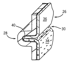
[0030] Referring to FIG. 2, trim panel 16 is shown adjacent a window 24 and
comprises a sheet (shown as a coverstock 26) joined to a base (shown as a
substrate 28).
Upper portion 18 of trim panel 16 is separated from middle portion 20 of trim
panel 16 by a
first recess 30 formed in coverstock and substrate. Middle portion 20 of trim
panel 16 is
separated from lower portion 22 of trim panel 16 by a second recess 32 formed
in substrate
28.
[0031] Referring to FIG. 3, a roll 34 of coverstock material is shown prior to
fabrication of coverstock 26 that is used to form trim panel 16 (e.g., prior
to being stamped,
cut, etc.). FIG. 9 is a perspective view of a process for texturing, printing,
and die cutting
the coverstock. Referring to FIGS. 3 and 4, coverstock 26 comprises a first
portion 36 and a
second portion 38. First portion 36 of coverstock 26 comprises a first
decorative
characteristic or element and second portion includes a second decorative
characteristic or
element different than the first decorative element. The decorative elements
may provide
any of a variety of ornamental appearances such as colors, textures, patterns
(e.g., images,
indicia, text, designs, etc.), or combinations thereof that are formed, added,
provided on,
printed on, painted on, or otherwise disposed on the side or surface of the
coverstock 26 that
ultimately at least partially faces the vehicle interior 10 (e.g., the visible
surface or the "A-
surface"). Coverstock 26 may be made from any of a variety of materials and
compositions
including fabric (woven, non-woven, etc.) textile, natural, polymer, or the
like or
combinations thereof; and may have multiple layers (e.g., outer, inner, scrim,
etc.).
[0032] According to exemplary embodiments, coverstock 26 provides two or more
delineations that are registered (e.g., designed, located, disposed, assigned,
etc.) to specific
areas (e.g., portions, regions, sections, etc.) of trim panel 16. Registered
textures or patterns
can be added to the base, one-piece sheet by embossing arid other methods
known to those
skilled in the art of fabric or sheet manufacture. Registered colors or
patterns can be applied
to the base, one-piece sheet with various silkscreen or ink application
processes. For
example, the coverstock material may be fabricated by feeding the roll 34 of
fabric through
one or more machines that apply one or more registered textures or patterns
and/or one or
more registered colors or patterns to provide varied ornamental appearances on
a single
piece of fabric. According to a preferred embodiment, decorative elements are
printed (e.g.,
with ink, paint, dye, laser printing, ink jet, painting, etc.) on the A-
surface of coverstock that
-6-
CA 02591390 2007-06-14
WO 2006/076129 PCT/US2005/045898
has been embossed with a texture, using any of a variety of conventionally
known methods
(e.g., pressure embossing, thermal embossing, etc.). According to alternative
embodiments,
the decorative elements are provided on the coverstock by adding material
(e.g., deposits of
polymeric adhesives, paint or other materials) on the A-surface of coverstock.
The different
decorative appearance may be provided by two different elements applied to the
coverstock,
or a single element applied to the coverstock that provides a different
decorative appearance
(or texture) than the rest of the coverstock. According to another alternative
embodiment,
decorative elements are provided on coverstock by physical or chemical
alterations to the
A-surface of coverstock (e.g., attaching elements, embossing, stamping, heat
application,
ultrasonic, etc.). FIG. 9 is a perspective view of a process for texturing,
printing, and die
cutting the coverstock according to an exemplary embodiment.
[0033] Separating first portion 36 from second portion 38 is a border 40
(e.g.,
interface, demarcation, delineation, division, line, etc.). FIGS. 3 and 4 show
border 40 as a
linear line, but the border may be provided as an accurate line, enclosed
sections or regions
(e.g., circular, elliptical, oval, square, rectangular, etc.) on the A-surface
of the one-piece
coverstock 26, or the like. Such a single piece of fabric with multiple
ornamental or
decorative demarcations is then be placed into a mold (tool) and molded so
that the different
areas of the fabric correspond to different areas of the panel (e.g., a door
panel upper and
lower bolsters). According to alternative embodiments, the coverstock may be
provided
with three or more portions having two or more different decorative elements.
[0034] Referring to finished trim panel 16 in FIGS. 2 and 8, border 40 between
first portion 36 and second portion 38 of coverstock 26 is located in first
recess 30 formed
in substrate 28 when substrate 28 is molded against or behind coverstock 26.
[0035] FIG. 10 is a schematic view of a process for forming the door trim
panel
according to an exemplary embodiment. Referring to FIGS. 5-7, first recess 30
and second
recess 32 in substrate is provided or formed during the molding operation that
forms
substrate 28. FIG. 5 shows a mold 42 having a first mold section (shown as a
cavity 44)
and a second mold section (shown as a core 46). The interior surface of cavity
44 includes a
first recess 48 to at least partially receive a first projection 50 extending
from core 46, and a
second recess 52 configured to receive at least a portion of a second
projection 54 extending
from core 46. First projection 50 and second projection 54 may be any of a
variety of
members extending from the surface of the core (e.g., blade, pins, etc.).
Placement and
-7-
CA 02591390 2007-06-14
WO 2006/076129 PCT/US2005/045898
location of recesses and projections on the illustrated mold sections are
exemplary, such that
one or both (or more as the design may provide) may be on the other mold
section.
[0036] Coverstock 26 is positioned between cavity 44 and core 46 when mold 42
is open. According to an exemplary embodiment, coverstock 26 includes
apertures 56
(shown in FIG. 4) that receive projections (shown as pins 58) extending from
core 46. In
this position, coverstock 26 is suspended (e.g., hangs) from pins 58. Pins 58
are configured
to engage recesses 60 in cavity 44 when the mold 42 closes. Coverstock 26 may
be placed
in mold 42 by any of a variety of techniques including robotic placement,
manual
placement, vacuum device, adhesive, or the like.
[0037] FIG. 6 shows mold 42 closed around coverstock 26 (e.g., by moving the
mold sections toward each other (or one of the sections towards the other
section) so that a
cavity or gap 62 is provided between core 46 and cavity 44. The placement and
orientation
of coverstock 26 generally follows the contours of the mold sections.
[0038] Referring to FIG. 7, molteri polymer resin is injected into gap 62
between
core 46 and coverstock for upper portion 18 and middle portion 20 of trim
panel 16 between
cavity 44 and core 46 for lower portion 22 of trim panel 16. As molten plastic
resin fills
gap 62, coverstock 26 is pressed against the surface of core 46 and takes the
shape of the
surface of core 46 (i.e., the desired final shape of trim panel). According to
an exemplary
embodiment, the substrate is molded such that the coverstock is disposed over
a portion of
the substrate (e.g., partial mold behind) and the non-covered portion of the
substrate may
provide a portion of the A-surface of the trim panel. According to another
exemplary
embodiment, the substrate is molded such that the coverstock is disposed over
the entire
substrate (e.g., mold behind) and the coverstock provides the entire A-surface
of the
combined article.
[0039] Referring to FIGS. 2, 7, 8, first recess 48 in cavity 44 and first
projection
50 on core 46 are configured (e.g., located, oriented, etc.) so that border 40
is located or
disposed within first recess 48 after polymer resin has been injected into gap
62. Also,
second recess 52 in cavity 44 and second projection 54 on core 46 are likewise
positioned or
located so that the edge of coverstock 26 is disposed in second recess 52
after polymeric
molten resin has filled gap 62. When mold 42 is opened, projections 50, 54 are
removed
from recesses 30, 32 formed in coverstock 26 and/or substrate 28, and from
recesses 48, 52.
[0040] According to an exemplary embodiment, the demarcations between upper
portion 18, middle portion 20, and/or lower portion 22, are defined by the
general desired
-8-
CA 02591390 2007-06-14
WO 2006/076129 PCT/US2005/045898
configuration or orriamental appearance of door trim panel 16. Likewise,
placement of
recesses 30, 32 (and border 40, projections 50, 54, and recesses 48, 52) are
designed or
configured according to the desired design and ornamental appearance of trim
panel 16. As
such, first recess 48 and second recess 52 are similarly defined in position
by this design;
and coverstock 26 is designed (configured) so that border 40 between first
portion 36 and
second portion 38 ends up being located in first recess 48 in substrate 28.
According to a
preferred embodiment, the relative location of border 40 (between first
portion 36 and
second portion 38 in coverstock 26) is determined by analyzing and testing the
properties
(e.g., stretch, elongation, movement within the mold during molding of the
substrate, etc.)
of the material or materials used to form coverstock 26 (e.g., empirically,
trial and error,
computer software or program, or the like) and the flow and pressure of the
injected plastic
during molding of the substrate. These characteristics and properties are then
applied and
used to design coverstock 26.
[0041] After plastic resin forms substrate 28, the trim panel 16 can undergo
any of
a variety of finishing operations (e.g., removing any portions of coverstock
not attached to
substrate (e.g., the portion or strip containing apertures), wrapping around
and coupling to
the B surface of substrate (e.g., by fasteners, adhesives, welding, heat
staking, etc.) or the
like).
[0042] FIG. 11 is a flow diagram of a process of making a vehicle door panel
with
a coverstock with two or more printed decorative characteristics or elements
according to an
exemplary embodiment. The process includes printing the fabric so that it
presents two or
more decorative characteristics or elements. These characteristics may be
provided, for
example, by one decorative characteristic that is a printed indicia and
another decorative
characteristic that is another (e.g., different) printed indicia, the base
appearance of the
fabric (itself), a texture, or the like. The preformed sheet may then be
trimmed to a desired
shape or configuration. The trimmed fabric is then inserted into the mold tool
and the
substrate is molded by injection of plastic resin.
[0043] FIG. 12 is a flow diagram of a process of making a vehicle door panel
with
a coverstock with two or more painted decorative characteristics or elements
according to
an exemplary embodiment. The process includes cutting a sheet that forms the
coverstock
and then preformed to a desired shape (e.g., by vacuum forming or the like).
According to a
preferred embodiment, the sheet comprises three layer laminate (i.e., a"tri-
laminate") of a
vinyl topcoat layer, a foam layer, and a polypropylene backing layer. The
laminate is
-9-
CA 02591390 2007-06-14
WO 2006/076129 PCT/US2005/045898
heated and then vacuum formed to a desired shape with the division line (i.e.,
border)
between the two decorative characteristics or elements residing in a formed
recess or ditch.
The formed coverstock is trimmed and then placed in a fixture. A paint mask is
placed over
the portion of the coverstock that is not to be painted (e.g., an upper or
lower bolster) and
the part is then painted. The painted preformed coverstock is then placed in
an injection
molding tool and plastic resin in injected to the mold to form the substrate.
A portion of the
substrate forms structural support for the coverstock and a portion of the
substrate may also
form a visible portion of the trim panel (e.g., part of the "A-surface"). The
division or line
between painted portions or between portions painted and not painted is
located in the a
recess or ditch formed in the substrate at the recess formed in the coverstock
preform.
[0044] It is also important to note that the construction and arrangement of
the
elements of the vehicle trim panel as shown in the preferred and other
exemplary
embodiments is illustrative only. The method may be used for manufacture of
any of a
variety of trim panels having multiple decorative elements, which may be
provided as any
of a variety of shapes or configurations on the trim panel. Although only a
few
embodiments of the present inventions have been described in detail in this
disclosure, those
skilled in the art who review this disclosure will readily appreciate that
many modifications
are possible (e.g., variations in sizes, dimensions, structures, shapes and
proportions of the
various elements, values of parameters, mounting arrangements, use of
materials, colors,
orientations, etc.) without materially departing from the novel teachings and
advantages of
the subject matter recited. For example, elements shown as integrally formed
may be
constructed of multiple parts or elements show as multiple parts may be
integrally formed,
the operation of the interfaces (e.g. clamps, etc.) may be reversed or
otherwise varied, the
length or width of the structures and/or members or connector or other
elements of the
system may be varied, the nature or number of adjustment positions provided
between the
elements may be varied (e.g. by variations in the number of engagement slots
or size of the
engagement slots or type of engagement). It should be noted that the elements
and/or
assemblies of the system may be constructed from any of a wide variety of
materials that
provide sufficient strength or durability, in any of a wide variety of colors,
textures and
combinations. It should also be noted that the display system may be used in
association
with a rotating display, or alternatively other, fixed and non-movable
displays or any of a
wide variety of other surfaces in any of a wide variety of other applications.
Accordingly,
all such modifications are intended to be included within the scope of the
present
-10-
CA 02591390 2007-06-14
WO 2006/076129 PCT/US2005/045898
inventions. Other substitutions, modifications, changes and omissions may be
made in the
design, operating conditions and arrangement of the preferred and other
exemplary
embodiments without departing from the spirit of the present inventions.
-11-