Note: Descriptions are shown in the official language in which they were submitted.
CA 02591493 2012-05-17
TREATMENT OF ANAL INCONTINENCE
BACKGROUND
[0002] Anal incontinence is a common problem that occurs in both men and
women,
though is certainly more prevalent in women after vaginal childbirth,
presumably the result
of trauma to pelvic floor muscles, supporting fascia and nerves. Fecal
incontinence affects
an estimated 7.6 percent of women between the ages of 30¨ 90. The prevalence
increases
with age, affecting 3.6 percent of women between 30¨ 39 and 15.2 percent of
women
between 80 ¨ 90. Several factors contribute to anal continence, including the
resting tone
of the external and internal anal sphincters, as well as the position of the
levator ani
muscles, especially the puborectalis muscle, which forms a sling around the
rectum and is
responsible for the so-called "ano-rectal angle," which keeps stool in the
rectum until
voluntary defecation relaxes the puborectalis muscle and straightens the
angle, allowing
stool to move towards the anus.
[0003] Defecation is often aided by expulsive abdominal forces. Anal
incontinence may
occur as the result of several mechanisms, including direct damage to the
internal or
external anal sphincters (from iatrogenic episiotomy or spontaneous
lacerations during
vaginal delivery), or to the levator ani muscles. It may also result from
indirect injury of
these muscles through denervation of the nerves that supply these muscles.
Treatment of
this problem has centered on pelvic floor rehabilitation, dietary changes, or
surgical
correction. Surgery has been used to treat specific defects in the anal
sphincters, such as
external anal sphincteroplasty. Success rates of only 50% or less are
generally reported for
these procedures on long-term follow-up.
[0004] More recently, an artificial anal sphincter has been used to bypass
these muscles,
though this surgery involves fairly extensive dissection and requires the
patient to depress a
subcutaneous valve which temporarily deflates the sphincter cuff and allows
voluntary
- 1 -
CA 02591493 2012-05-17
defecation. This procedure is performed in very few centers in the U.S., and
even in
experienced hands, complications occur frequently. Dynamic graciloplasty,
which
involves mobilization and wrapping of the gracilis muscle around the anorectum
is now
another accepted procedure although is remains complex and requires extensive
experience to obtain good results. More recently, sacral nerve stimulation has
been used
with some success to treat fecal incontinence, though the mechanism of success
in these
patients remains unclear, and may not be appropriate in women with obvious
anatomic
abnormalities, such as anal sphincter or levator muscle disruptions.
[0005] In addition, many women report other symptoms of bowel dysfunction,
such as
constipation and incomplete bowel emptying. For some women, these symptoms are
due
to either a anterior rectocele (a hernia of the rectum into the vaginal
canal), or due to a
defect in the levator ani muscles, which results in descent of the levator
plate and / or
perineum with abdominal straining. In addition, patients may be noted to have
a defect in
the posterior aspect of the rectum, or a posterior rectocele. There are very
few treatment
options for this condition, though retrorectal levatorplasty has been used in
the past. In this
procedure, an incision is made between the anus and the coccyx and the levator
muscles
are exposed bilaterally. Sutures are then placed in the levator muscles to
plicate them
together in the midline.
SUMMARY
[0006] The present disclosure describes systems and methods for treating anal
incontinence, and other types of defecatory dysfunction, such as perineal
descent,
constipation, incomplete bowel emptying, and rectal prolapse. Some disclosed
systems
and methods particularly facilitate minimally-invasive treatment of anal
incontinence.
[0006a] According to an aspect, there is provided a use of a sling for
treating anal
incontinence, wherein the sling comprises:
a central portion having at least two arms extending therefrom;
- 2 -
CA 02591493 2013-11-25
the central portion configured to be positioned posteriorly to the rectum
and/or
anus of a subject wherein each arm of the sling comprises a mesh strap having
a length
sufficient to extend to a respective obturator region; and wherein the central
portion of the
sling has a shape that conforms to the external contour of the anus, rectum,
ano-rectal
angle, and/or levator ani muscles.
[0006b] According to another aspect, there is provided a sling for use in
treating anal
incontinence, the sling comprising a central portion having at least two arms
extending
therefrom;
the central portion configured to be positioned posteriorly to the rectum
and/or
anus of a subject wherein each arm of the sling comprises a mesh strap having
a length
sufficient to extend to a respective obturator region; and wherein the central
portion of the
sling has a shape that conforms to the external contour of the anus, rectum,
ano-rectal
angle, and/or levator ani muscles and further wherein said central portion has
a sub-rectal
extension element extending therefrom that is sized and structured for
attachment to a
coccyx of the patient.
BRIEF DESCRIPTION OF THE DRAWINGS
[0007] FIG. 1 depicts the anatomy of the bony pelvis.
100081 FIG. 2 depicts an exemplary placement of a device in the pelvis.
[0009] FIGS. 3-4 depict steps in one exemplary placement method.
100101 FIGS. 5-6 depict steps in another exemplary placement method.
[0011] FIG. 7 depicts an exemplary final position of a length of supporting
material.
10012] FIGS. 8-10 depict exemplary uses of two lengths of supporting material.
- 2a -
CA 02591493 2007-06-20
WO 2006/069078 PCT/US2005/046201
[0013] FIGS. 11-19 depict exemplary uses of various instruments to position a
length of
supporting material.
[0014] FIGS. 20-22 depict exemplary slings.
[0015] FIGS. 23-25 depict exemplary slings having fluid-filled sacs.
[0016] FIGS. 26-29 depict an exemplary use of a stylet having a loop.
[0017] FIGS. 30-31 depict an exemplary use of a stylet having a hook.
[0018] FIGS. 32-38 depict additional exemplary embodiments of slings.
[0019] FIG. 39 depicts use of an exemplary device to measure the ano-rectal
angle.
[0020] FIGS. 40-41 depict placement of a sling having a saddle-shaped central
portion.
DETAILED DESCRIPTION
[0021] The present disclosure provides a variety of systems and methods for
treating anal
incontinence. The normal ano-rectal angle can be restored by inserting a
disclosed device
under the posterior rectum, which may be supported with a synthetic or natural
material in a
sling-like position behind the anus and/or rectum. A posterior supporting
apparatus may
provide partial or complete closure of the rectum and/or anus with the
posterior supporting
apparatus.
[0022] In one embodiment, a synthetic or natural sling material may be placed
under the
rectum and may be supported by its arms, which may be extended up in a sling-
like fashion
through the obturator foramen bilaterally, or retropubically to the suprapubic
region. In
another embodiment, the device placed posterior to the rectum may include an
inflatable or
fluid-filled sac, which may or may not be adjusted post-operatively, by either
changing its
position or by altering the amount of fluid material, for example saline or a
hydro gel, within
the sac. "Fluid" is understood to include gasses, liquids, and semisolid media
(such as
gels). In some embodiments, the central portion of the sling may have a curved
shape, such
as a saddle shape, to help it conform to the external contour of the anus,
rectum, ano-rectal
angle, and/or levator ani muscles.
[0023] In one embodiment of a method of treating anal incontinence, an
incision may be
made between the anus and the coccyx and dissection performed, whereby the
levator
muscles and the levator plate are exposed. A small nick may be made on the
medial thigh
just lateral to the ischiopubic ramus and an introducer needle may be placed
through the
medial thigh incision, around the ischiopubic ramus, and be directed
posteriorly into the
ischiorectal fossa. The needle may then be directed lateral to the levator
muscles, optionally
- 3 -
CA 02591493 2007-06-20
WO 2006/069078
PCT/US2005/046201
with the assistance of a surgeon palpating the instrument though the vagina.
The needle
may then be brought posterior to the rectum, exiting the incision that was
made in the
midline. Alternatively, the needle may be passed from the midline incision
between the
anus and coccyx to the medial thigh incision lateral to the ischiopubic ramis.
In one
embodiment, a suture may be threaded onto the eye of the needle, which in this
case may be
placed from the medial thigh to the incision between the anus and the coccyx,
and may then
be withdrawn through the tissue and held on the medial thigh. The procedure is
repeated on
the contralateral side. A synthetic (i.e., polypropylene, polyester, etc.)
mesh (such as
tension-free vaginal tape, TVT) or natural graft material may then be attached
to each of the
sutures coming from the midline incision, and the mesh may then be brought up
through the
medial thigh incisions by pulling up on the sutures.
[0024] The mesh may have a covering plastic sheath, which can facilitate
passage through
the tissues. The sheath may be removed when the sling is properly adjusted.
[0025] In another embodiment, the needle that is passed through the tissue may
have a
hollow sleeve or tube over it (e.g., made of plastic, metal, or the like), and
after passage, the
needle may be withdrawn through the tissue, leaving the hollow sleeve in
place. A stylet
(e.g., made of plastic, metal, or the like) may then be then placed in the
tube. The stylet
may have a connector, such as a hook or a loop, so that a length of supporting
material,
such as a synthetic mesh (e.g., made of polypropylene or the like) or a
natural graft, may be
attached to the stylet connector. Exemplary uses of stylets with hooks or
loops are shown
in FIGS. 26-31. Once this procedure is performed bilaterally, the supporting
material may
be positioned under the rectum and the tension on the arms of the sling are
adjusted. If the
sleeves or tubes are utilized, the mesh can be adjusted before withdrawing the
sleeves or
tubes.
[0026] In another embodiment, two passes of the needles can be made on each
side, one
approximately at the level of the medial superior portion of the obturator
foramen, and the
other several centimeters inferior and slightly more lateral (at the inferior
portion of the
obturator foramen). This permits two lengths of supporting material (also
called "mesh" but
not necessarily limited to mesh) to be brought up on each side. These mesh
strips are
attached to a central mesh that may be placed under the rectum, which may be a
pre-formed
mesh, or may be constructed by attaching the central mesh to the four mesh
strips ¨ two on
each side. The subrectal portion may be synthetic mesh, or may be made of
another
material, such as an inflatable or fluid-filled polymer sac. The sub-rectal
element provides
- 4 -
CA 02591493 2007-06-20
WO 2006/069078
PCT/US2005/046201
support to the posterior anus and/or rectum, and creates an angle between the
anus and
rectum, which keeps stool in the rectum until voluntary defecation.
[0027] In another embodiment, after the needle passes through the tissue, and
is withdrawn,
leaving a hollow tube in place, a plastic or metal stylet, previously fixed to
the mesh with or
without a sheath, can be placed up from the sub-rectal incision to the medial
thigh incision
and can be held. The mesh may then be brought up through the tubing by pulling
on the
stylet from above. Once the sling end comes out from the tubing, the hollow
tube can be
removed, after the sling has been adjusted for proper tensioning.
[0028] In another embodiment, the posterior aspect of the sub-rectal portion
may be
attached to the coccyx by one of several methods, such as direct suturing or
with bone
anchors. Such attachment can help maintain the position of the sub-rectal
portion, which, in
effect, restores the structure and function of the levator plate.
Alternatively, the sub-rectal
portion may have an extension coming off its inferior portion, which extends
out and is
fixed to the coccyx.
[0029] The fluid-filled sac under or adjacent to the rectum may have a port,
such as a
subcutaneous port, that may allow for fluid addition or removal in the post-
operative
period. This port may facilitate post-operative adjustment of the size and /
or shape of the
sac to provide for optimal results. The subcutaneous port may be placed
directly under the
sac, in the perineal skin, or may be connected to the sac by means of a
connector tubing so
that the port does not need to be located in the perineum itself, but instead
may be
positioned in a number of areas, including, for example, the buttocks.
[0030] The needle may have a hook near the end, that can be covered during
insertion, but
that may be exposed after the needle has been placed through the tissue. The
user
implanting the device may operate a switch or other actuator, such as a spring-
loaded
mechanism, to expose the hook. The arm of the sling, or a pre-loaded suture on
the sling-
arm, may then be placed on the hook and the needle withdrawn through the
tissue.
[0031] In another embodiment, once the needle is placed through the tissue,
the tip of the
needle may be unscrewed off the end of the needle shaft. The arms of the sling
may have a
device attached to each end that may screw onto the needle shaft or otherwise
fasten onto
the needle shaft and then the needle is withdrawn, bringing the sling arm
through the tissue.
[0032] A sheath covering the needle may remain in place in order to facilitate
the
movement of the synthetic material through the tissue, which is only removed
once the
tension on the sling is adjusted. The sheath may be deformable, rather than
rigid or semi-
- 5 -
CA 02591493 2007-06-20
WO 2006/069078
PCT/US2005/046201
rigid, and may be flattened after removal of the needle, to accommodate the
flat shape of
the sling material itself.
[0033] The needle could have blunt metallic insert (to maintain the strength
of the needle)
with a plastic covering sheath that has a sharp needle tip configuration on
the end. After the
needle is placed through the tissue, the metallic blunt needle is withdrawn,
and the plastic
needle tip cut off. A suture retriever is then placed anterograde through the
hollow plastic
tube and grasps a suture that has been attached or pre-attached to the sling.
The sling is
withdrawn through the plastic tube and the tube is removed once the sling is
adjusted.
[0034] In another embodiment, the needle tip may be made from two separate
pieces that
act as jaws that open to catch the mesh or suture attached to the mesh, after
the needle is
passed through the tissue from the medial thigh to the incision posterior to
the anus. This
needle may be introduced with a plastic outer covering, so that the sling
material may be
drawn up through the tissue without catching on the surrounding structures.
Once in proper
position, the surgeon may remove the plastic sheath, which would then allow
for the
synthetic mesh to become fixed in the tissues.
[0035] A curved metal needle may be placed through the tissue from the medial
thigh to the
perineal incision. The end of the needle may be unscrewed, and the sling with
attached
plastic or metal piece may be screwed or snapped onto or into the connector on
the needle.
The sling, possibly with covering sheath, may then be withdrawn through the
tissue and
held and the plastic sheath is removed after the sling has been adjusted.
[0036] The shape of the sling may be a fixed width throughout its length.
Alternatively, the
central portion that is positioned under/behind the rectum may be wider than
the arms. The
central portion may be curved to help it conform to the shape of the tissue it
is supporting.
The curved shape may be a saddle shape, such as roughly a hyperbolic
paraboloid or
resembling a PRINGLESO brand potato crisp. The central portion may be
preformed with
the curved shape.
[0037] The mesh may be continuous throughout the length of the sling, or may
have a
central portion that includes a fluid-filled sac that is affixed to the sling
arms on the sides.
Preferably, the synthetic mesh would be continuous throughout its length in
order to
provide a backboard of support under the rectum and under the fluid-filled
sac, if the fluid-
filled sac is employed.
[0038] The fluid sac may have a circular or elongated shape under the rectum,
or may
include several compai __ tllients that can be separately filled with several
access ports, in
- 6 -
CA 02591493 2007-06-20
WO 2006/069078 PCT/US2005/046201
order to change the occlusion of the rectum. The fluid filled sac may have the
curved
shapes as discussed above.
[0039] Wings may connect a sling central portion to the arms of the sling. The
wings may
be made of mesh or other supporting material.
[0040] In another embodiment, the sling may be a hybrid of materials,
comprised of, for
instance, a polypropylene mesh along the arms of the sling in order to have
self-attaching
properties to the obturator fascia, and a natural xenograft material, such as
porcine small
intestinal submucosa, or an allograft, such as cadaveric fascia, located under
and or lateral
to the anus / rectum.
[0041] In another embodiment, the arms of the sling may include a synthetic
material such
as silastic or other plastic, and may have serrations that grab on to the
obturator fascia as the
arms are pulled through the tissue.
[0042] In another embodiment, the arms of the sling include sutures. There may
be several
sets of sutures on each side, in order to prevent the sub-rectal portion of
the sling from
rolling up underneath the anorectum.
[0043] In another embodiment, the arms of the sling may be attached to pelvic
bone, such
as the inferior-medial portion of the ischiopubic rami, or the inferior
portion of the pubis,
with bone anchors, suture material, or other fixation devices.
[0044] In another embodiment, the material under and / or lateral to the ano-
rectum
includes a synthetic material, such as silastic or other plastic material,
that may be flexible,
to conform to the shape of the bowel.
[0045] In another embodiment, a number of synthetic or natural elements are
attached to
the mesh in a direction transverse to the length of the sling, such as
perpendicular or
substantially perpendicular to the length of the sling. The elements may be
semi-rigid and
may be so positioned in the mesh as to be located under or lateral to the
bowel when the
mesh is deployed, for the purpose of keeping the mesh from rolling up
underneath the
anorectum. For example, the graft may have a stiff or flexible bar
incorporated into the
graft, located on either side of the rectum, to prevent rolling of the graft
material.
[0046] In another embodiment, the sling may have additional straps attached to
the
subrectal portion that penetrate posteriorly, such as on either side of the
coccyx, that may
pass through the subcutaneous tissue and hold the graft in position, to
prevent rolling of the
subrectal mesh.
- 7 -
CA 02591493 2007-06-20
WO 2006/069078 PCT/US2005/046201
[0047] In another embodiment, the synthetic material may be elastic, which may
permit
stretching of the sling with abdominal straining, such as occurs with
voluntary defecation.
[0048] In another technique, the sling may be passed through the levator ani
muscle, rather
than behind the muscles.
[0049] In another embodiment, the system may include a device used to evaluate
the ano-
rectal angle, for pre-operative diagnosis, intra-operative adjustment, and/or
post-operative
evaluation. The device is sufficiently flexible that it can be flexed to
conform to the ano-
rectal angle. The amount of flexion may be measured, thereby establishing the
shape of the
ano-rectal angle. In one embodiment, the device may be inserted into the
rectum and has a
flexible joint which is placed at the junction between the anus and rectum.
The device may
then measure the angle created between the rectal and anal portions, and this
angle may be
displayed visually on the device, in one of a number of manners, including a
dial or a
digital display. The angle may also be communicated to an external display for
convenience. The device may include a rotation- or position-sensitive
transducer. This
ano-rectal angle measurement device may be adapted so that is fits over the
examiner's
gloved finger with a portion that fits over or on the examiner's distal
finger, and another
portion that fits over or on the proximal finger. In this manner, when the
examiner bends his
or her finger to determine the ano-rectal angle, the measured angle is
recorded visually on a
display.
[0050] Various portions of the device may be coated, impregnated, or formed
with one or
more drugs to be eluted to an adjacent tissue. Various portions of the device
may be
formed of biodegradable or bioabsorbable material.
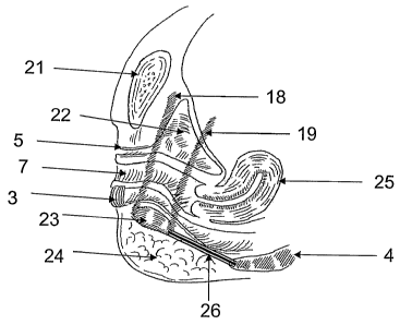
[0051] FIG. 1 shows the anatomy of the bony pelvis, with the pubic symphysis
(6), the
ischiopubic ramus (2), the ischial tuberosity (9), the coccyx (4), and the
obturator foramen
(1). It also demonstrates the relationship of the levator ani muscles (and, in
particular, the
puborectalis (8)) to the urethra (5), vagina (7), and rectum (3).
[0052] FIG. 2 demonstrates the placement of a needle (11) and attached handle
(10) from
the medial thigh incision (12), through the obturator membrane, into the
ischiorectal fossa,
and the needle tip (14) emerging through the vertical incision (13) between
the anus and the
coccyx.
[0053] FIGS. 3-4 depict steps in one exemplary placement method. In FIG. 3,
the needle
(11) with the attached handle (10) has been placed through the thigh incision
and through
the obturator foramen, through the ischio-rectal fossa and out through the
incision (13)
- 8 -
CA 02591493 2007-06-20
WO 2006/069078
PCT/US2005/046201
between the anus and the coccyx. A suture loop (33) attached to the sling (16)
is grasped
by the needle tip (14) in order to transfer the sling to the thigh incision.
FIG. 4
demonstrates the second pass of the needle on the contralateral side with the
handle (10)
and needle (11) in place. The tip (14) is grasping the suture loop (33) in
order to pull the
other arm of the sling up through to the thigh incision. This allows the
central portion of the
sling (20) to rest under the ano-rectal area.
[0054] FIGS. 5-6 depict steps in another exemplary placement method. In FIG.
5, the
needle (11) with attached handle (10) has been placed from the post-anal
vertical incision
(13) up through the ischiorectal fossa, through the obturator foramen, and out
through the
thigh incision, and has transferred a suture attached to the sling (18) to the
thigh region.
This allows the sling to be brought through the tissues up to the region of
the thigh. FIG. 6
shows the right side of the sling in place and the needle (11) with attached
handle (10)
transferring a suture attached to the left side of the sling arm (16) up
through the left side.
The suture is being held by the needle tip (14).
[0055] FIG. 7 demonstrates a final position of the synthetic mesh (16) under
the anus
and/or rectum, with the incision between the anus and the coccyx (17), and up
through the
medial portion of the obturator membrane (15).
[0056] FIG. 8 demonstrates the use of two synthetic mesh straps placed through
the
obturator membrane, the first more distal and placed near the superior-medial
aspect of the
obturator foramen (18), and the second placed near the inferior portion of the
obturator
foramen (19), and attached to a central element (20).
[0057] FIG. 9 shows a lateral orientation of the pelvis with the pubic
symphysis (21), the
bladder (22), the uterus (25), and the ischiorectal fossa (24) with two
synthetic straps on
each side, the first more distal (18) and the other more proximal (19), and a
sub-rectal
element (23) that includes a fluid or gas filled reservoir.
[0058] FIG. 10 shows a lateral orientation of the pelvis with the sling in
place, with an
extension (26) of the sub-rectal element attached to the coccyx with the use
of sutures, bone
anchor, or other method of affixing the synthetic material to the coccyx.
[0059] FIGS. 11-13 demonstrate the use of a needle (27) introducer placed from
the medial
thigh to the incision under of the rectum. Once through the tissue, the jaw
opens in the
middle, which reveals a grasping instrument (28) that can hold on to a suture
(29) affixed to
the mesh (30) with or without a plastic sheath (31). The sling material is
then brought
- 9 -
CA 02591493 2007-06-20
WO 2006/069078
PCT/US2005/046201
through the tissue, with or without a plastic outer tubing (26) through which
the grasper had
been placed during the needle insertion..
[0060] FIGS. 14-16 demonstrate a needle (32) that, after insertion through the
tissue, can
be advanced beyond the outer sheath, with or without a spring-mechanism to
deploy the
needle. This reveals a notch, on which the suture loop (previously attached to
the mesh),
can be placed (33), and the sling (30) is then brought up through the tissues
to the medial
thigh
[0061] FIGS. 17-19 demonstrate a needle (34) that, after insertion through the
tissue, may
be separated from the shaft of the needle by unscrewing the needle tip. The
sling would
have a male-connector screw (36) that attaches to the straight needle shaft
(35) and then the
needle is withdrawn, which draws the mesh up through the tissue.
[0062] FIG. 20 demonstrates a sling that has narrow arms (16) and a wider area
which
would sit under the rectum (37) and distribute forces over a wide area. FIG.
21 illustrates a
sling central portion (arms not shown) that has a curved shaped, specifically,
a saddle
shape. The saddle shape may facilitate making good contact with the anatomy to
be
supported. Its positioning is illustrated in FIGS. 40-41. One curve of the
saddle allows the
sling to arc between the obturator regions, while the other curve can
complement the
anorectal angle. FIG. 22 demonstrates an elongated central sling (20) with
four attached
arms, two of which are passed from the medial superior portion of the
obturator membrane
(18), and the other two which are passed through the inferior portion of the
obturator
membrane (19).
[0063] FIG. 23 demonstrates a superior view of a mesh that has a fluid-filled
sac on the
superior side of the graft material.
[0064] FIG. 24 shows another embodiment of a sling having a central portion
with an
inflatable sac. Connector tubing is attached to the fluid-filled sac and can
be placed under
the buttocks or other location within the reach of the tubing, and has a port
at the end that
can be used for filling or reducing the amount of fluid is contained within
the sac.
[0065] FIG. 25 demonstrates an inferior view of the central portion (20),
which shows a
port from the fluid-filled sac coming out through a hole at the bottom of the
graft (40). This
port may be accessed subcutaneously in order to either add more fluid or
remove fluid.
[0066] FIGS. 26-29 exhibit an exemplary use of a loop stylet. Stylet (41) may
be advanced
through tube (42). A length of sling material (43) may be threaded through the
loop so that
- 10 -
CA 02591493 2007-06-20
WO 2006/069078 PCT/US2005/046201
the material catches in the loop. The stylet may then be withdrawn back
through the tube to
bring the end of the sling material to the desired position.
[0067] FIGS. 30-31 show an exemplary use of a hook stylet (44). A piece of
sling material
(45) may be stabbed onto a sharp tip of the hook. The hook may then be
withdrawn
through a tube to bring the end of the sling material to the desired location.
[0068] FIG. 32 shows a hybrid sling, comprised of, for instance, synthetic
mesh arms
attached to a central natural material placed under and / or lateral to the
ano-rectum.
[0069] FIG. 33 shows the sling with additional straps of material that are
attached to the
subrectal portion of the device, and are secured in place by passage into
subcutaneous
tissue, in order to prevent rolling of the sling. The straps may be directed
posteriorly, on
either side of the coccyx, in order to keep the subrectal portion flat.
[0070] FIG. 34 demonstrates a sling made of a synthetic material such as
silastic or other
plastic with serrations on each arm that maintain the sling in position after
adjustment by
the surgeon
[0071] FIGS. 35-37 show embodiments of slings that include rigid or semi-rigid
elements
(46). The elements may be attached to the sling in order to keep the sling
from rolling
under the ano-rectal portion.
[0072] FIG. 38 shows the use of bone anchors to hold the sling into position,
in this case to
the inferior-medial portion of the ischiopubic rami.
[0073] FIG. 39 depicts a device attached to the examiner's finger used to
measure the
angle between the rectum (3) and anus. The vagina (7) rests anterior to the
anus and rectum,
and the coccyx (4) is located posterior to the rectum. A proximal ring (54) is
placed on the
proximal phalanx (51) and the distal ring (55) is placed on the distal phalanx
(50) and these
are connected by a joint (53). The angle made between the anus and rectum is
measured
and displayed on a visual scale (52).
[0074] In one exemplary embodiment, a method to treat anal incontinence and/or
defecatory dysfunction in a male or female may include:
[0075] placing an implant that passes under the anus and / or rectum and may
pass
under, over, or through the levator ani muscles;
[0076] placing one of the ends of the implant through the obturator foramen
and
through an incision made in the medial thigh on the same side of the patient;
and
[0077] providing an elongate instrument that is used to transfer one end of
the
implant from the post-anal incision to a medial thigh incision, and then
transferring
-11-
CA 02591493 2007-06-20
WO 2006/069078 PCT/US2005/046201
the other end of the implant from the post-anal incision to the other medial
thigh
incision; or
[0078] providing an elongate instrument that is used to transfer one end of
the
implant from a medial thigh incision to the post-anal incision, and then
transferring
the other end of the implant from the other medial thigh incision to the post-
anal
incision.
[0079] In another exemplary, a method of treating anal incontinence and / or
defecatory
dysfunction in a male or female patient may include:
[0080] creating an incision between the anus and the coccyx (vertical or
horizontal);
[0081] creating an incision in the medial portion of each thigh;
[0082] providing an elongate instrument and an elongate implant for treating
the
condition;
[0083] passing one of the ends of the instrument between the post-anal
incision,
through an obturator foramen on one side of the patient, and the incision on
the
respective medial thigh;
[0084] associating the implant with the instrument;
[0085] using the instrument to pass the implant through the tissue between the
post-
anal incision and one thigh incision such that the implant extends between the
post-
anal incision, through the one obturator foramen, and one of the thigh
incisions;
[0086] passing one of the ends of the same or another instrument between the
post-
anal incision, through the other obturator foramen, and the other thigh
incision; and
[0087] using the instrument to extend the implant between the post-anal
incision,
through the other obturator foramen, to the other thigh incision such that the
implant
then extends from one thigh incision to the other thigh incision, through both
obturator foramen and under the patient's rectum and / or anus (below or above
the
level of the levator ani muscles).
[0088] Various embodiments disclosed herein can be combined with one another
to provide
additional embodiments that include multiple features.
- 12 -