Note: Descriptions are shown in the official language in which they were submitted.
CA 02591580 2007-06-15
WO 2006/066350 PCT/AU2005/001959
-1-
TITLE: SIMPLE GAS SCOURING METHOD AND APPARATUS
TECHNICAL FIELD
The present invention relates to membrane filtration systems and, more
particularly, to an improved method and apparatus for gas scouring filtration
membranes.
BACKGROUND OF THE INVENTION
Gas scouring systems have been used with membrane filtration systems to
clean membranes and allow such systems to operate effectively over long
periods with a reduced need for regular backwashing or high backwashing
io efficiency. Such systems typically employ pressurized gas generated by a
blower or pump to produce gas bubbles which flow along the membrane
surfaces and scour accumulated solids and impurities therefrom. The need for a
pressurised source of gas normally requires an expensive pump and a power
supply. While this is not of concern with large commercial systems, the cost
of
1s the gas supply is seen as disadvantageous to be able to provide such
scouring
methods to smaller systems, for example home filter systems. Such advantages
are seen as having application in remote areas (farms, remote villages,
expeditions) where it is hard to get electricity and pressurized air but where
sufficient water pressure (about 50 to 400 kPa) is available to operate the
20 system.
DISCLOSURE OF THE INVENTION
The present invention seeks to provide a gas scouring system to run
without the need for a pressurized gas supply.
According to one aspect the present invention provides a method of
25 cleaning a membrane in a membrane filtration system by flowing gas bubbles
CA 02591580 2007-06-15
WO 2006/066350 PCT/AU2005/001959
-2-
past the surfaces of said membrane to scour accumulated solids therefrom, the
method including :
a) flowing a liquid past a supply of gas;
b) creating a reduced pressure within said liquid flow to cause a flow of
gas from said supply of gas into said liquid flow and form gas bubbles
therein;
c) flowing said liquid containing said gas bubbles past the surfaces of said
membrane to scour the surfaces thereof.
Preferably, the reduced pressure is created in an eductor or venturi device.
For preference, the liquid includes feed liquid supplied to the membrane
filtration system.
BRIEF DESCRIPTION OF THE DRAWINGS
Preferred embodiments of the invention will now be described, by way of
example only, with reference to the accompanying drawing in which:
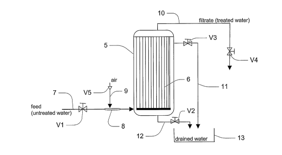
Figure 1 shows a schematic of the membrane filtration system according to
one embodiment of the invention.
DESCRIPTION OF PREFERRED EMBODIMENTS
Referring to Figure 1, the system comprises a membrane filtration module
5 having a plurality of membranes 6 mounted therein. A feed line 7 feeds
untreated water through valve V1 and eductor/venturi 8 to the module 5. Gas,
typically air, is fed to the eductor 8 through gas line 9 and check valve V5.
Filtrate is withdrawn from the membranes 6 through filtrate line 10 controlled
by
filtrate valve V4. The module 5 is provided with upper and lower drain lines
11
and 12 controlled by respective upper and lower drain valves V3 and V2. The
drain lines 11 and 12 feed into a drain tank 13.
CA 02591580 2007-06-15
WO 2006/066350 PCT/AU2005/001959
-3-
In use, the untreated water enters through valve VI and through the
eductor 8 into the membrane module 5. Under normal operating conditions the
drain valves V2 and V3 are closed. When treated water (filtrate) is required
valve V4 (tap) is opened and the water pressure pushes the water through the
membranes 6 to the filtrate side and the filtrate produced flows through valve
V4
and filtrate Iine10. As the flow rate is limited by the membrane resistance,
the
speed of the water flowing in the eductor 8 is not high enough to suck air
into the
water stream. Instead the water pressure will cause the check valve V5 to
close. If necessary, the flow rate can be further controlled by valve V4, V1
or an
io optional flow control valve installed between V4 and the module. If the
membranes begin to block up, the following procedure may be used to clean the
membranes:
a) The filtrate valve V4 is kept closed and to drain valve V3 is opened.
This causes water to flow at a high flow rate through valve VI, the
eductor 8 and through the membrane module 5. The water exits
through upper drain valve V3 and can optionally be collected in the tank
13 for further use like irrigation. As the water can pass along the
membrane module without the restriction by the membranes 6, the flow
rate in the eductor/venturi 8 is high enough to create a suction
pressure. This causes air to enter through the check valve V5 through
the eductor into the feed water stream producing bubbles therein. The
air bubbles in combination with the strong water flow scours any fouling
layer from the membranes and flushes the removed suspended solids
out through valve V4.
CA 02591580 2007-06-15
WO 2006/066350 PCT/AU2005/001959
-4-
b) If a stronger cleaning action is required some or several of the following
process steps can be added:
i) Close Valve 3. This leads to the built-up of the water pressure
in the system and compresses the air trapped in the module
housing. After closing the feed valve V1 the bottom drain valve
V2 is opened. This will make the air expand and sweep part of
the remaining liquid out of the membrane module 5, carrying
more solids out. Further compressed air is sometimes required
to be applied to the vessel to assist removal of liquid from the
module.
ii) If necessary an additional sweeping step can follow by opening
upper drain valve V3 until the membrane module 5 is
completely drained.
iii) The valves V2 and V3 are closed. By opening valve V1 the
water pressure is applied and compresses the air in the filter
housing. Feed water takes the space made available by the
compression of the air. Repeating steps i) and ii) gives the
membranes 6 an additional clean.
iv) The valves V2 and V3 are closed. Opening valve V1 allows
water to enter into the membrane module 5. Carefully purging
through valve V3 allows the entrapped air to be removed.
Then valve V3 is closed and the system is back on line and
normal filtration resumes.
CA 02591580 2007-06-15
WO 2006/066350 PCT/AU2005/001959
-5-
It will be appreciated by those skilled in the art of membrane filtration that
a
variety of sequencing of the valves can be used in order to achieve a desired
outcome.
The eductor 8 is a piece of equipment that uses the dynamic flow of water
to create a partial vacuum which causes air to enter into the water flow.
Typically this is a venturi pipe or some kind of jet.
If a chemical clean of the membrane is required, an additional liquid
connection to the eductor 8 may be used to suck any cleaning chemical into the
liquid stream during cleaning. After a short period of time the liquid flow
may be
io stopped by shutting valve V1 in order to save chemicals and to allow the
membrane to soak in the solution of the chemical.
The cleaning system may be applied to any form of membrane including
fibre, flat sheet, spiral wound, pleated or plate types.
The filter system may be combined with an appropriate activated carbon
filter or the like to remove taste and odour.
It will be appreciated that further embodiments and exemplifications of the
invention are possible without departing from the spirit or scope of the
invention
described.