Note: Descriptions are shown in the official language in which they were submitted.
CA 02591811 2007-06-20
WO 2006/066349 PCT/AU2005/001958
- 1 -
A FOOD PREPARATION MOULD
Technical Field
The present invention relates generally to a mould,
and more specifically to a single use mould for food
preparation. The invention has particular application for
baked products such as cakes and is herein described in
that context. However, the invention is not limited to that
application and may also be used in other applications,
such as in forming pastry shells, cold set food products
such as mousses and cheesecakes or other non-food products
such as plaster and wax.
Background of the Invention
Moulds are often used as a tool for food preparation
where a metered amount of batter is placed in the mould
cavity. This process may be done manually, but in
commercial operations, a depositor may be used to automate
this process. Further, in the making of pastries such as
flans and quiches an overhead platen typically descends
under force to locate the pastry base evenly on the base
and may drive the pastry mix up between a gap between the
overhead platen and the edge of the mould. A filling may
then be deposited on formed pastry base.
One very common type of mould is the cake tin. Cake
tins may have a peripheral wall of fixed shape. Others have
a wall structure that is separable from the base and can be
opened up to allow easy discharge of the cake from the tin.
These tins, known as springforms, are widely used in
industrial applications and are typically made from metal.
Although moulds such as the springform tins are
designed for multiple use, in a commercial environment they
tend to limit commercial production rates in that they
require cleaning before use. Furthermore, by re-using the
CA 02591811 2007-06-20
WO 2006/066349 PCT/AU2005/001958
- 2 -
moulds, it is usually not feasible to leave the product in
the moulds after it has been baked. Therefore the moulds
are only used in preparation of the product and additional
packaging is required for preparing the product for
transport and sale.
Summary of the Invention
In a first aspect, the invention provides a mould
comprising a base; a collar having a continuous wall
extending between opposite upper and lower edges, and one
or more tabs extending from the lower edge, the collar
upstanding from the base with the lower edge abutting the
base; and retaining means operative to retain the tabs in
relation to the base so as to retain the lower edge of the
collar in proximity with the base.
In accordance with the mould of the above form the
location of the collar on the base defines a cavity in
which batter or other settable material may be located.
In one form the collar wall incorporates a releasable
connection to enable opening of the collar. In this way
the mould may operate in a similar manner to a springform
tin.
In a particular arrangement, the collar is made from
sheet material having opposite end edges that interconnect
the upper and lower edges, the end edges being in abutting
or overlapping arrangement to form the continuous wall. In
particular embodiment, the releasable connection is formed
between the opposite ends of the collar.
In a particular form, to allow easy release of the
collar from the base, a frangible connection is formed
between the tabs and the collar wall. That frangible
connection may be formed by perforation, or by reducing the
thickness of the material, at the connection or by other
CA 02591811 2007-06-20
WO 2006/066349 PCT/AU2005/001958
- 3 -
techniques known in the art.
In a particular embodiment, the mould is made so that
at least the collar is for single use and is made from
fibreboard, which if the mould is for baked products, is
ovenable. The fibreboard may be carton board, or
corrugated board and may be coated with suitable ovenable
polymeric coatings include polyester, polypropylene,
silicone or polytetrafluoroethylene. Suitable sheets
include solid-bleached sulphate (SBS) or corrugated
linerboard having a PMP coating manufactured by
MeadWestvaco. MeadWestvaco 'Printcote Ovenable' may be one
commercial example of ovenable material board. In an
alternate form the collar can be formed from coated paper
which is one form is ovenable. Suitable sheets of coated
paper include kraft paper.
In one form, the retaining means arranged to maintain
the tabs in close proximity to the base, is by way of
bonding of at least some of the tabs to the base. For
example, adhesive may be applied between the tabs and the
base. In another form, where the tabs and/or the base
include a polymeric material, the bonding may occur on the
application of heat and pressure. In another form, the
mode of securing the tabs to the base may be by virtue of a
mechanical fastening arrangement. Such a fastening
arrangement may be formed by forming interlocking elements
in both the tabs and the base.
In one particular form, the tabs extend out of the
plane of the collar and the retaining means comprises at
least one overlay element that locates over the tabs and
the base so as to cause the tabs to be entrapped between
the overlay element(s) and a surface of the base.
In a particular form, the proximal end of the tabs may
be disposed above the lower edge of the collar. In this
way, the tabs can be folded out of the plane of the wall of
SUBSTITUTE SHEET (RULE 26)
CA 02591811 2007-06-20
WO 2006/066349 PCT/AU2005/001958
- 4 -
the collar and wherein when folded, the tabs are designed
to align with the lower edge of the collar so as to
maintain contact between the collar and base along the
entire periphery of the collar.
In one form, at least some of the tabs extend
outwardly out of the plane of the collar and wherein the
mould further comprising a locking member having an inner
edge disposed around the periphery of the collar, the
locking member forming the overlay element (or at least one
of the overlay elements) so that the outwardly directed
tabs are entrapped between the locking member and the base.
In a particular embodiment, the locking member is
formed from sheet material such as fibreboard. In one
form, the locking member is made from ovenable fibreboard
such as those described above in relation to the collar.
In one form, the locking member is formed from a
unitary structure. However, this unitary structure may be
replaced in other embodiments by a series of smaller
elements. Thus, the term "locking member" as herein is to
be construed not only for a single element, but also a
functioning equivalent arrangement of shorter sections of
such an element.
In a particular arrangement, the locking member is
bonded to the base. The locking member may be secured to
the base in various ways. For example, adhesive may be
applied between the locking member and the base. In
another form, where the locking member and/or the base
include a polymeric material, the bonding may occur on the
application of heat and pressure to the engaging members.
In another form, the mode of securing the locking member to
the base may be by virtue of a mechanical fastening
arrangement. Such a fastening arrangement may be formed by
forming interlocking elements in both the locking member
and the base.
CA 02591811 2007-06-20
WO 2006/066349 PCT/AU2005/001958
- 5 -
In one form, the locking member is bonded to the base
along one or more regions that are spaced outwardly from
the inner edge of the locking member. In a particular
form, the bond is applied by the application of pressure to
the locking member and the base. An advantage of this
arrangement is that the forming of the bond may tend to
open up a gap between the inner edge of the locking member
and the base which can facilitate the location of the tabs
therebetween.
In one form, the mould further comprises an insert
which is locatable within the collar in a snug fit with the
wall and the base of the mould. In one form the insert is
formed of sheet material and in a more particular form, the
insert is made from an ovenable fibreboard or paper such as
those described above with reference to the collar.
In one form, at least some of the tabs extend inwardly
out of the plane of the collar and the insert forms the
overlay element (or at least one of the overlay elements)
so that the inwardly directed tabs are entrapped between
the insert and the base.
In general, it is necessary to form an adequate seal
between the collar and the base to inhibit excessive
leaking of batter from the mould. The provision of such a
seal is made more problematic in baked products where the
batter expands in the mould as it is being baked, thereby
increasing the pressure at the joint between the base and
collar.
In one form, the retaining means is adequate to
provide the seal so that the engagement of the lower edge
of the collar with the base provides the main seal. In
another form the insert located in snug fit with the inner
surface of the collar wall may also contribute to providing
the seal.
CA 02591811 2007-06-20
WO 2006/066349 PCT/AU2005/001958
- 6 -
In one form, to further improve the seal between the
collar and the base, the upper surface of the base
incorporates an annular recess in which the lower edge of
the collar locates.
In a further aspect, the invention provides a mould
comprising a base; a collar having a continuous wall
extending between opposite upper and lower edges, the
collar upstanding from the base with the lower edge
abutting the base; and an insert disposed within the collar
in a snug fit with the wall of the mould, the insert
providing at least part of a seal to inhibit leaking of
material within the mould from between the collar and the
base.
In one embodiment, the collar, base and insert may be
of any form described above. Further, in one form of this
latter aspect of the invention, the mould may further
comprise tabs and retaining means described above.
In a particular embodiment, the mould of any form
described above, further comprising support means operative
to support the collar wall.
In one form, the inner edge of the locking member is
arranged to bear against the collar wall so as to form at
least part of the support means arranged to support the
collar wall.
In one form, the support means is operative to support
the collar wall along a region spaced from the lower edge
of the wall. In a particular arrangement of this later
form, the base includes spaced apart upper and lower
members, each of the members being formed from sheet
material, the lower edge of the collar being disposed on
the lower member and wherein the upper member includes an
opening to receive the collar, wherein the upper member
CA 02591811 2007-06-20
WO 2006/066349 PCT/AU2005/001958
- 7 -
further includes an abutment surface arranged to bear
against an intermediate region of the collar so as to form
at least -part of the support means arranged to support the
collar wall. A suitable base of this type is disclosed in
International patent application WO 2004/066735, entitled
"A Food Preparation and Distribution Tray", the contents of
which are herein incorporated by cross reference. In this
arrangement, the upper and lower members are interconnected
by one or more side walls so that the base has a box like
construction.
An advantage of at least one form of the mould is that
it can be made in many different shapes in view of the
collar being made from sheet material that is disposed
generally edge on to the base. However, in some instances
it is difficult to maintain the shape of the collar,
particularly where there are sharp corners and the like.
The use of the support means assists in enabling the
collars to keep their shape.
In a further aspect, the invention provides a mould
comprising a base; a collar having a continuous wall
extending between opposite upper and lower edges, the
collar upstanding from the base with the lower edge
abutting the base; and support means operative to support
the collar wall.
In one embodiment, the collar, base and support means
may be of any form described above.
In a further form of this latest aspect, the mould
includes an insert as described above.
In a particular embodiment in any of the forms
described above, the base is formed from sheet material,
which may be the same material as the locking member and/or
the collar, typically being a fibreboard which in one form
may be ovenable. In an alternative form the base may be
CA 02591811 2007-06-20
WO 2006/066349 PCT/AU2005/001958
- 8 -
formed from coated paper which in one form is ovenable.
Suitable ovenable polymeric coatings include polyester,
polypropylene, silicone or polytetrafluoroethylene.
An advantage of embodiments of the mould of the
present invention is that a mould is inexpensive to
manufacture as it can be made from inexpensive material
such as fibre board. Accordingly, the mould may be
economically employed as a single use product.
A further advantage of the mould is that mechanical
product portioning can be completed after baking without
first removing the baked product from the mould. In using
the mould in this manner the mould can now support and
protect the individual portions during transportation.
A further advantage of the mould according to a
particular embodiment is that the mould may also form part
of the packaging of the product. In this regard, the
insert and/or the base may be used as the support structure
for the product. In another arrangement, both the base and
the collar remain in tact and help protect and facilitate
handling of the product to its point of sale. In this
latter arrangement, the collar may also be printed if
required.
A further advantage of using a fibreboard for a baking
mould is that it allows for even distribution of heat
through the product being baked as the compared to
traditional metal moulds where the metal will heat up to an
extent where it causes a significant impact on heat
distribution.
The mould when formed from the sheet may be provided
to its point of use in a knocked down form and assembled on
site. In this regard, in a further form, the invention
provides a fibreboard preform for forming a mould according
to any form described above, the preform comprising a
SUBSTITUTE SHEET (RULE 26)
CA 02591811 2007-06-20
WO 2006/066349 PCT/AU2005/001958
- 9 -
collar; and a base arranged to receive the collar.
Typically these elements would be provided in a substantial
sheet form thereby facilitating transporting and storage.
Brief Description of the Drawings
It is convenient to hereinafter describe embodiments
of the food preparation mould with reference to the
accompanying drawings. The particularity of the drawings
and the related description is to be understood as not
superseding the generality of the preceding broad
description.
In the drawings:
Fig. 1 is a exploded perspective view of a food
preparation mould.
Fig. 2 is a plan view of the locking member and base
of the mould of Fig. 1;
Fig. 3 is a plan view of perform for the collar of the
mould of Fig. 1;
Fig. 4 is a detailed cross-sectional view of the joint
between the base of the mould of Fig. 2;
Fig. 5 shows the detailed cross-sectional view of the
joint of Fig. 4 with the insert and locking member in
place;
Fig. 6 is an exploded perspective view of a second
embodiment of a food preparation mould;
Fig. 7 is a detailed cross sectional view of the joint
between the collar and the base of the mould of Fig. 6;
Fig. 8 is the detailed cross sectional view of the
joint of Fig. 7 with the insert in place;
Fig. 9 is a perspective view of a third embodiment of
a food preparation mould; and
Fig. 10 is a sectional view along section line X-X of
Fig. 9.
CA 02591811 2007-06-20
WO 2006/066349 PCT/AU2005/001958
- 10 -
Detailed Description
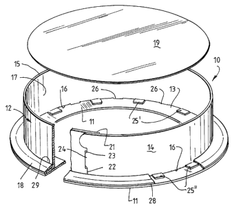
Turning firstly to Fig. 1, a mould which in the
illustrated form is designed for baking comprises a flat
base 11 and a collar 12 which extends upwardly from an
upper surface 13 (see Fig. 4) of the base 11. The collar
12 has a continuous wall 14 which extends between upper and
lower edges (15 and 16 respectively). The collar locates
on the base 11 and defines a cavity 17 in which batter or
other liquid or semi liquid material is received.
The mould 10 further includes a locking member 18
which has a cut-out in the form of an annular ring which is
bonded to the upper surface 13 of the base 11 (as shown in
Fig. 5) and designed to retain the collar in engagement
with the base as will be described in more detail below.
The locking member 18 is sized so as to protrude slightly
from the base 11 to thereby provide an edge surface to lock
a lid (typically a thermo-formed lid) to the base. An
insert 19 is also provided which locates within the cavity
17 so as to locate against the upper surface 13 of the base
11. The insert 19 is designed to locate snugly against the
inner surface of the collar wall 14 (see Fig. 5) so as to
provide at least part of a liquid seal between the collar
12 and the base 11.
The components of the mould 10 are all formed from
sheet material. With reference to Figs. 2 and 3, in the
illustrated form, the base 11, the locking member 18 and
the insert 19 may all be formed from a single sheet.
Further each of these components are merely cut from the
sheet. In this regard, the insert 19 is formed from the
portion of the sheet removed in forming the hole in the
annular locking member 18. Moreover in the embodiment as
shown, the base 11 is integrally formed with the locking
member 18 through a hinge connection 20 which is formed by
a fold line in the sheet material.
CA 02591811 2007-06-20
WO 2006/066349 PCT/AU2005/001958
- 11 -
Turning to Fig. 3, the collar 12 is similarly formed
from sheet material with opposite ends 21, 22 of the collar
sheet being interconnected so as to form the continuous
wall of the collar.12. In the arrangement as shown, a
releasable coupling is formed at the interconnecting ends
21, 22. In the arrangement one end 21 includes a slot 23
whereas the other end 22 includes a tongue 24 which locates
in that slot. Alternatively the releasable coupling is
formed by the overlaying of the upper edge 15 of one end 21
of the collar 12 over the upper edge 15 of the opposite end
22 of the collar 12.
The collar 12 also includes a plurality of tabs 25
which extend from the lower edge 16 of the collar 12.
These tabs are integrally formed with the wall 14 of the
collar and which are connected to the wall by frangible
connections 26. These frangible connections 26 are
disposed inboard slightly of the edge 16 and are typically
formed by perforating the sheet. In the embodiment shown
the tabs 25 are of different length with tab 25= being
slightly larger than tabs 251=. Further, the tabs are
arranged to that the longer tabs 25= alternate with the
shorter tabs 25==. It is to be appreciated that in another
form, the tabs may be of uniform length.
In the embodiment as illustrated, the mould is made
from a ovenable food grade coated board such as that
supplied by MeadWestvaco. The collar 12 may include a
silicon coating.
The tabs are designed to be received between the
locking member 18 or insert 19 and the base 11 so as to
effectively retain the collar to the base. In this way the
locking member 18 and the insert 19 act as overlay elements
to retain the collar in proximity with the base. This is
best illustrated with reference Figs. 4 and 5.
When assembling the mould 10, the lower edge 16 of the
CA 02591811 2007-06-20
WO 2006/066349 PCT/AU2005/001958
- 12 -
collar 12 locates on the upper surface 13 of the base 11 as
best illustrated in Fig. 4. An annular recess 27 may be
formed in the base to both facilitate locating of the
collar 12 in place and also to improve the contact between
the collar 12 and the base 11. In locating the collar 12
in place, the locking tabs 25 are turned out of the plane
of the collar wall 14. As the connections 26 between the
wall 14 and the tabs 25 are above the lower edge 16, that
edge 16 is disposed below the locking tab 25 so as to
locate fully within the groove 27. In the illustrated form
the shorter tabs 2521 extend outwardly so as to be
substantially parallel and abutting with the upper surface
13 of the base 11 whereas the longer tabs 25= extend
inwardly.
As illustrated in Fig. 5, the locking member 18
locates over the base 11 so that the tabs 25=I are retained
between the base 11 and the locking member 18. The locking
member is secured to the base 11 so that the tabs 25== are
firmly retained between those elements. The method of
fixing the locking member 18 to the base 11 may be via a
pressure sensitive glue applied to one or both of the base
and the locking member or by sonic welding or by
reactivation of glue by radio frequency or microwave or by
a mechanical fastening arrangement or the like. This may
be done prior to, or after, the tabs are located in place.
In the illustrated form, the locking member 18 is
bonded to the base along its outer peripheral edge 28.
This bonding is done under pressure which forms a
continuous seal and also causes the inner edge to be
slightly raised from the base 11. The raising of the edge
29 facilitates location of the tabs 2512 between the locking
member 18 and the base 11. It also allows the inner edge
29 of the locking member to bear against the collar wall 14
at a location which is slightly further spaced from the
lower edge 16 of the collar 12.
CA 02591811 2007-06-20
WO 2006/066349 PCT/AU2005/001958
- 13 -
The inner edge 29 of the collar 18 is arranged to bear
against the collar wall 14 so as to support the wall to
assist in maintaining its shape during baking. As a cake
is baked, it expands which places pressure on the collar
wall tending it to deformed. This tendency to deform is
resisted in this embodiment by the inner edge 29 of the
locking ring 18 which acts as a support means for the
collar wall.
To complete the assembly of the mould 10, the insert
19 is located within the cavity 17 and therefore provides a
base for the cake. The insert 19 locates in a snug fit
against the collar wall 14 thereby further supporting the
collar wall. Moreover, the insert overlays the inwardly
directed tabs 252 thereby forms part of the retaining means
which maintains the lower edge of the collar 16 in
engagement with the base 11. The insert 19 also
contributes to sealing between the collar 12 and the base
11.
Turning to Figs. 6 to 8, a second embodiment of a
mould 30 is illustrated. As the mould 30 includes many of
the features of the earlier embodiment, like reference
numerals have been given to like features.
Consistent with the earlier embodiment, the collar 12
of the mould is arranged to locate on the base 11. Again
both the base and the collar are made from fibreboard which
is ovenable. Furthermore, the collar incorporates the tabs
25 which project downwardly from the lower end 16 of the
collar 12. In the version of the mould 30 as illustrated,
the tabs 25 are of uniform length.
The main distinction between the mould 30 and the
previous embodiment 10 is that a different approach is used
to retain the tabs 25 in engagement with the base 11. In
particular, rather than using a locking member 18 as
described in the earlier embodiment, the tabs are all
CA 02591811 2007-06-20
WO 2006/066349 PCT/AU2005/001958
- 14 -
turned inwardly and are bonded directly onto the base 11
using an adhesive 31 as best illustrated in Figs. 9 and 10.
A locking member 18 is not required and, as such, the base
does not project significantly beyond the perimeter of the
collar 12.
Again, as in the earlier embodiment, the insert 19
locates within the cavity 17 so as to locate snugly against
the inner surface of the collar wall 14. Further, the
insert entraps the tabs 25 between the insert and the base.
As distinct from the earlier embodiment, the collar
wall 14 is not separately supported. As such, the mould 30
is better suited to situations where there is not excessive
pressure build up in the mould during formation of the
product. As such, the mould 30 is well suited to cold set
products or where the baked product is relatively thin.
A third embodiment 40 of the mould is illustrated with
reference to Figs. 9 and 10. Again, as the embodiment of
the mould 40 includes many of the features of the earlier
embodiment, for convenience like features have been given
like reference numerals.
In contrast to the earlier embodiments, the mould 40
is arranged to produce multiple independent cakes or
muffins (six in the illustrated form), rather than an
individual cake as in the earlier embodiments.
Furthermore, the base 11 forms part of a tray 41 which is
arranged to provide additional support for the collars 12
(only two of which are shown) as will be discussed in more
detail below. This tray 41 is also ovenable and is the
subject of international patent application W02004/066735,
entitled "A Food Preparation and Distribution Tray" the
contents of which are herein incorporated by cross
reference. However, instead of using
the individual paper "patty" cups as disclosed in that
earlier application, the mould 10 uses the collars 12 which
CA 02591811 2007-06-20
WO 2006/066349 PCT/AU2005/001958
- 15 -
are retained against the base 11.
As best illustrated in Fig. 10, the tray 41 includes a
lower (or base) member 11, an overlaying element 42 which
is disposed on the base member 11, and an upper member 43
which is spaced both from the overlay member 42 and the
base member 11. Both the overlay member 42 and the upper
member 43 include cut outs (which in the illustrated form
are circular) to receive the collar 12.
In this way, the collar 12 is able to locate with its
lower edge 16 on the base member 11. Furthermore the
collar includes the tabs which project inwardly into the
cavity of the individual moulds 17. The insert 19 locates
within the cavity 17 so that the tabs 25 are entrapped
between the insert 19 and the base member 11 in a similar
manner as disclosed above. Because in the illustrated form
the collars are of only relatively small diameters, the
inventors have found that there is no need to separately
bond the tabs 25 to the base member 11. It is sufficient
to retain the lower edge 16 in engagement with the base 11
merely by havingthe tabs 25 disposed inwardly and located
under the insert 19. Because the insert 19 is a snug fit
with the collar wall 14 and because the overlay element 42
bears against the collar wall 14, there is an adequate seal
which prevents leakage of batter from between the collar 12
and the base 11.
A significant feature of the embodiment 40 is that the
upper member 43 bears against the collar of the mould 40 in
spaced relation from the lower edge 16. This therefore
supports the collar 12 to retain its shape during use of
the mould.
The mould 40 is ideally suited to produce individual
cakes which are tall relative to their diameter. Further,
while the mould 40 is for making multiple cakes, it is to
be appreciated that it could be modified for single use
CA 02591811 2007-06-20
WO 2006/066349 PCT/AU2005/001958
- 16 -
application.
In use, the moulds 10, 30, 40 are ideally suited for
commercial kitchens where the moulds are provided either in
knock down form and assembled on site or preassembled.
Once assembled, pastry dough or batter, which may be in a
liquid or in a flowable state form, is then inserted in the
cavity 17 whereafter the batter is allowed to set typically
by heating or cooling.
After the product has been formed the collar can be
stripped from the base simply by releasing the ends 21 and
22 of the collar 12 and tearing off the wall section 14 of
the collar from the retaining tabs 25. Alternatively, the
collar may be used as part of the product packaging and is
thereby left in place after the product has set.
An advantage of the moulds 10, 30, 40 is that they are
inexpensive to manufacture as they are made merely from
coated board or coated paper and is therefore ideally
suited for single use. In addition, all components are
made from sheet material thereby obviating the need for any
expensive moulding equipment. This simplifies the
manufacturing process and in particular allows for the
dimensions of the mould to be easily varied to suit
customer needs. The moulds are also ideally suited to be
included into complex shapes such as hearts or the like.
A further advantage of the moulds 10, 30, 40 is that
the seal provided has been found satisfactory for both
baked and cold set products regardless of how liquid the
original batter is. Accordingly, the mould is well suited
to be used over a wide range of products in food
preparation.
Whilst the food preparation mould has been described
with reference to a specific embodiment, it should be
appreciated that the mould can be embodied in many other
CA 02591811 2007-06-20
WO 2006/066349 PCT/AU2005/001958
- 17 -
forms. In particular, the mould may be used in
applications other than food preparation.
In the claims which follow and in the preceding
description of the food preparation mould, except where the
context requires otherwise due to express language or
necessary implication, the word "comprise" or variations
such as "comprises" or "comprising" is used in an inclusive
sense, i.e. to specify the presence of the stated features
but not to preclude the presence or addition of further
features in various embodiments of the mould.