Note: Descriptions are shown in the official language in which they were submitted.
CA 02592226 2007-07-09
Application number / nuir,.6ro de demande: ~7 o2 02 ~
Pxguzes: p e`t re (/aJ
Unscamble item(s)
received wi.& this application
To inquire if you can order a copy of the unscamable ite;m.s, please visit the
CIPO WebSxte at HTTP://CTPO.GC.C.A
Item(s) ne pouvaut et-e balayes
Documents resus avec cette deniande ne pouvant 6fre balay6s.
Pour ~vous renseigner si vous pouvez commander une copie des items ne
pouvant etre balayo, veWliez visitor le site web de YCPZC au HTTTP ://CIP4.GC.
CA 02592226 2007-07-09
r~ nsfi~,z,.yf.i
S.
44 TNE_ BCUi_EL'AMD
r-
~l;i ;,:fr.
4+'iCTOt-i6A, AYõlSt RALIA
~ C S f) M c PriOtvc: --51) 34 5879
MORWELL -200.r~ .) ~:1/c-
Recently I've discovered a way on how to unite and harness three natural
forces to
generate large amount of electricity,incurring little expenditures in the
process.
Those three forces mentioned are,atmospheric pressure,gravity and marine
buoyancy.
Personally I think we are at the dawn of a new era in power generating,a
breakthrough in
technology,similar as the discovery of radio waves or aviation,to name a few
shining
ones.
Here is then a succinct expose of the intrinsic qualities and superiorities
over anything
known today of this invention,which is also as reliable as any kind of
existing power
houses;but unlike them all,being so expensive to run,due to the enormous
supply of
combustible;par contre,this element is inexistant in this invention,who do not
need
absolutely any alimental fuel to work perfectly well,there is a free
inexhaustible reserve
gf it;the vaste,infinite oceans.
This is to say,that without the onerous overhead cost of fuel saved,the price
to the
c}psumer could be reduced bu two third,when compared to the existing one.
Jiere is also an apercu about the difference between conventional heavily
laden costwise
power houses and this invention;no land to buy,no overburden to remove,no big
dredgers,no kilometres of convayors;no cooling towers;no high decibel noisy
turbines,
and no settling dams.
Also absolutely no air pollution;protection to ozonosphere;global warming
stumped
out;no more reeking high cheminees spewing large amount of deletereous gases
into the
atmosphere,no enormous furnaces burning megatons of coal producing steam,no
more
radioactive residues from atomic power plans;and no more ugly structures
scaring the
landscape.
TAink sir at the outcome,due to the affordability of low electricity
price,favorably now to
the conversion of water into its two basic gases,nearly all vehicles could be
converted
into hybride,either oxygene or hydrogene petrol machines;heating,cooling city
buildings;residential premises;the massive savings realised.
Par ailleurs,I'm well aware that the wind mill farms generators is a good step
in the right
direction,but the inherent fluctuating,or wimsical eolian motivator force,is
arguably an
inconvenience that can hardly be contructively addressed.
CA 02592226 2007-07-09
Whereas,and as stated above,my invention is totally exempt of such
insolvant,adverse
effects;it is truly HYDRO NRGYproductive systeme.
Also because,I'm sure,there is no other system existing today,being
equivalent,has
distinct advantages,or is as reliable and as profitable as this one.
For instance.in the mighty SNOWY RIVER SCHEME,OR COLORADO HUGE
DAM,the water spins only once the turbines and its gone;instead if an array of
this
device is installed inside,behind the wall,the water plays dual roles.
Incidently sir,such strutures could even be build inland,in a body of water
deep enough to
accommodate them,or perhaps a desuetuded building converted into an immence
reservoir, would also work perfectly well,even high cheminees for that
matter,would also
be fine.
Even in time of prolonged,severe drought,due to restrictive measures taken to
save
precious water,turbines would have to be put idle,but this systeme would never
stop using
repeatedly the same water,purring along smoothly for ever...
Also due to the future and progressively phasing out of oil exploration to be
supplanted
by this alternative buoyancy principle,it is pertinent to predict with the
highest degree of
accuracy,that an era of strong demand for cheap electricity consumption is an
absolute
certainty;thus requiring the urgent building of countless platforms offshore
around this
mainland and oversea,in vigorous response to satisfy the need of an ever
expanding,
insatiable market.
CA 02592226 2007-07-09
- la -
TITLE: HYDRO NRGY
FIELD OF THE INVENTION
This invention concerns submersible apparatus for driving a water turbine.
BACKGROUND OF THE INVENTION
This invention provides a submersible water turbine with a water turbine inlet
and a water
turbine outlet, the outlet being connectable to multiple chamber assemblies
which empty
CA 02592226 2007-07-09
and fill in sequence so as to provide constant water flow through the turbine
wherein each
assembly comprises a static submersible support structure with an assembly
inlet and an
assemblv outlet and within the assembly a static cylinder disposed to receive
turbine flow
through the inlet, an air conduit for admitting air into the static cylinder,
a moveable
cylinder having an overlapping end and an exposed end arranged to slide in the
static
cylinder during emptying and fil l ing, a flexible conduit connecting the
exposed end to the
assembly outlet, a valve in the assembly inlet, a valve in the assembly
outlet, means to
biass the moveable cylinder to slide into the static cylinder and control
means to operate
the valves and air admission in a sequence which causes continuous flow of
water
through the assembly.
Preferably each of the support structures are grouped around a turbine
support.
The support structure may be a vessel which is capable of excluding the water
in whicn
the vessel is in use immersed.
The valve may be a gate valve which is opened and closed by reciprocating
motion. The
assembly may compr'tse a moveable cylinder which is sealed to a static
cylinder by a seal
such as a rolling diaphragm.
The moveable cylinder may be biassed to slide on the static cylinder and
minimise the
total volume.
The means to biass the moveable cylinder may be a ring extending from the
cylinder and
one or more springs acting between the ring and the support structure to biass
the
moveable cylinder to coaxially overlap the static cylinder.
The capacity of the cylinders may be 4-5000 litres. The air conduit may be
connected to
an air pump and an intensifier. The biasing means may include a plunger and
the plunger
motion may drive an alternator.
CA 02592226 2007-07-09
BRIEF DESCRIPTION OF THE DRAWINGS
One embodiment is now described with reference to the accompanying drawings in
which:-
Figure 1 is an arrangement diagram showing the relative positions of the
turbine, turbine
support and the chamber assemblies in side view.
Figure 2 is a diagrammatic section of a chamber assembly in end view showing
full and
empty modes.
DETAILED DESCRIPTION WITH RESPECT TO THE DRAWINGS
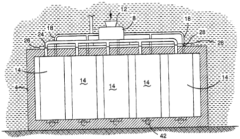
Referring now to the drawings, the apparatus is submerged in a large body of
water sucrt
as a lake or sound. The base 2 of the air-filled concrete caisson 4 is 25m x
4m. The
central part of the roof 6 in turn supports a turbine housing 8 and an
associated generator
10. The turbine takes in propulsion water in the area above the apparatus
through inlet
12. The spent water leaves turbine housing 8 through duct 12. This duct serves
two rows
of five chamber assemblies 14 arranged side by side, the purpose being to
connect the
chambers one after the other to the duct and produce a continuous stream of
water
fromousing to chamber. A common air duct has a branch 20 for each chamber
assembly
and extends to the water surface where is tied to a buoy (not shown) and
connected to a
compressed air pipeline (not shown).
The roof 2 supports the chamber assemblies of which one will be described. A
static
cylinder chamber 20 is closed at the top end and open at the bottom end.
Chamber 20 is
joined to the roof by seal 22. A gate valve 24 in a housing 26 on the roof
admits water
from the duct 12 into the static cylinder. Branch 18 also enters the cylinder
and is
controlled by air valve 28.
Moveable cylinder 30 is of somewhat greater volume and is free to slide in and
out of the
static cylinder as the latter fills and empties. The bottom of the moveable
cylinder 30
Pnds shnrt ofthe base 2 and the cylinder empties through flexible tube 32.
Exit fi-om tube
CA 02592226 2007-07-09
-4-
32 is controlled bv valve 34 in the base. Cylinder 30 is surrounded by ring
36.
Telescopic struts 38 extend between the ring and the base directly beneath.
Helical
springs in the struts biass the moveable cylinder to lie coaxially overlapped
by the static
cylinder leading to minimum volume of the two cylinders. One of the struts has
a screw
T which turns the nut of an alternator. Exit passages 42 in the base return
flow outside the
caisson.
The gate valves require hydraulic operation. The hydraulic circuit (not shown)
contains
a pump and motor which receives current from a grid. The valves, sequence of
operation
is under micro processor control. Exit valve 34 and inlet valve 24 open
together. Water
is free to fill the cylinders completely. The helical springs push the ring
upwards and the
moveable cylinder 30 comes to rest inside the static cylinder 20. Exit valve
34 and air
valve 28 both close together and air valve 28 opens. The moveable cylinder
descends
bending the flexible pipe 32 and compressing the springs. Water flows into the
cylinder
through inlet 24 which is replaced by water entering the turbine inlet. This
force is stored
and released at the next cylinder rise. All ten units work consecutively
providing a steady
flow through the turbine.
The illustrations, photographs and drawings, if any, form part of the
disclosure of this
specification as does the description, illustrations, photographs and drawings
of any
associated provisional or parent specification or of any priority document, if
any, all of
which are imported hereinto as part of the record hereof.
Finally it is to be understood that various alterations, modifications and/or
additions may
be incorporated into the various constructions and arrangements or parts
without
departing from the spirit and ambit of the invention.