Note: Descriptions are shown in the official language in which they were submitted.
CA 02592237 2007-06-19
VALVE PIN ACTUATING DEVICE FOR A HOT RUNNER APPARATUS
CROSS-REFERENCE TO RELATED APPLICATION
[0001] This application claims the benefit of U.S. provisional patent
application
no. 60/814,548 filed June 19, 2006, which is hereby incorporated by reference
in
its entirety herein.
BACKGROUND OF THE INVENTION
Field of the Invention
[0002] This invention is relates to an injection molding hot runner nozzle
valve
pin actuating apparatus, more particularly an actuating apparatus which
simultaneously actuates a plurality of valve pins.
Related Art
[0003] In injection molding, when melt material is delivered to one or more
mold
cavities, it is sometimes desired to simultaneously actuate the valves of a
plurality
of nozzles that regulate the flow of the melt. This can be the case when there
are
many nozzles each serving its own cavity or when many nozzles serve one
cavity.
[0004] An injection molding apparatus can include an array of nozzles that
have
valves that are simultaneously actuated via a yoke plate that is connected to
one or
more actuators; this is particularly useful in small pitch applications where
there is
not enough room between nozzles to accommodate individual actuators for each
nozzle. One problem that can occur with this type of apparatus is yoke plate
deflection caused by pressurized melt in the mold cavity pushing back on valve
pins. This can result in larger than acceptable witness marks on the finished
product or back-leakage of melt material from the cavity. This problem can
affect
any kind of injection molding where yoke plates are used.
CA 02592237 2007-06-19
-2-
[0005] Conventional solutions to yoke plate deflection include thickening the
yoke plate. However, thickening the yoke plate adds to the stack height of the
injection molding apparatus and adds significant cost to the injection molding
apparatus.
SUMMARY OF THE INVENTION
[0006] In an embodiment of the present invention, a valve pin actuating device
for a hot runner apparatus includes a yoke plate coupled to actuators. The
actuators are generally disposed at the ends of the yoke plate and are
configured
to move the yoke plate in a direction parallel to a longitudinal axis of the
valve
pins. The valve pins are coupled to a first force distributor plate. A
deflection
distributor apparatus is coupled to the yoke plate and disposed between the
yoke
plate and the first force distributor plate. The deflection distributor
apparatus
includes a second force distributor plate and a third force distributor plate.
Rods
are disposed between the yoke plate and the third force distributor plate,
between
the third force distributor plate and the second force distributor plate, and
between
the second force distributor plate and the first force distributor plate
holding the
valve pins.
[0007] In another embodiment of the present invention, a valve pin actuating
device includes a yoke plate connected to actuators and movable with respect
to a
mold clamp plate by the actuators. A plurality of force distributor plates are
connected to the yoke plate and a plurality of valve pins are connected to the
force
distributor plates. Rods form a bearing connection between the yoke plate and
the
force distributor plates.
CA 02592237 2007-06-19
-3-
BRIEF DESCRIPTION OF THE FIGURES
[0008] Embodiments of the present invention will now be described more fully
with reference to the accompanying drawings where like reference numbers
indicate similar structure.
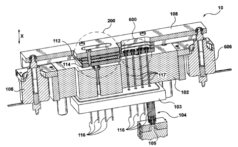
[0009] FIG. 1 is a perspective cross-sectional view of a mold assembly
according
to a first embodiment of the invention.
[0010] FIG. 2 shows a close-up partial sectional view 200 of the deflection
distributor apparatus of the mold assembly of FIG. 1.
[0011] FIG. 3 is a top view of the mold assembly of FIG. 1 without hidden
lines
shown.
[0012] FIG. 4 is a top view of the mold assembly of FIG. I with hidden lines
shown.
[0013] FIG. 5 is simplified side cross-sectional view of the mold assembly of
Fig.
1.
[0014] FIG. 6 is a close-up cross-sectional view 600 of four of the valve pin
adjustment devices of FIG. 1.
[0015] FIG. 7 is simplified side cross-sectional view of another embodiment of
the present invention.
DETAILED DESCRIPTION OF THE INVENTION
[0016] FIG. 1 shows a mold assembly 10 according to a first embodiment of the
invention. The mold assembly 10 comprises a mold clamp plate or back plate
102,
below which a conventional mold plate can be disposed, such mold plate holding
a manifold 103 fixed with respect to the back plate 102 and an array of
nozzles
104 (only one shown for clarity) connected to the manifold 103 to deliver melt
to
a mold cavity or cavities 105. As would be apparent to one of ordinary skill
in the
art, such a manifold 103 conventionally includes a manifold channel that
delivers
CA 02592237 2007-06-19
-4-
melt from a sprue to nozzle channels in the nozzles 104, through mold gates,
and
into the mold cavity or cavities 105. In addition, FIG. 1 omits other, well-
known
components such as additional mold pates, alignment pins, bolts, etc for
clarity.
At each end of the mold clamp plate 102 is an actuator assembly 106 that can
comprise a linear electric actuator, a hydraulic actuator, a pneumatic
actuator, or
any other actuator known in the art. The actuator assemblies 106 are connected
to
and adapted to move a yoke plate 108 up and down along an axis X. Connected
to the yoke plate 108 is a deflection distributor apparatus 112, which is
connected
to a first force distributor plate 114. The first force distributor plate 114
has valve
pins 116 connected thereto, such valve pins 116 running through holes 117 in
the
mold clamp plate 102 and controlling the flow of melt from the tips of the
nozzles
104 to the mold cavity or cavities 105. The first embodiment has eight valve
pins
116, yet any amount is acceptable. The deflection distributor apparatus 112
transfers force from the yoke plate 108 to the first force distributor plate
114 such
that when the actuator assemblies 106 move the yoke plate 108 up along the
axis
X the first force distributor plate 114 moves the valve pins 116 up likewise,
and
when the actuator assemblies 106 move the yoke plate 108 down along the axis X
the first force distributor plate 114 moves the valve pins 116 down likewise.
In
this way, the actuator assemblies 106 can be used to control the flow of melt
through the nozzles 104 into the cavity or cavities 105, and can do so in a
synchronized manner. When hydraulic or pneumatic actuator assemblies are
selected, the first force distributor plate 114 can act as a stop against the
mold
clamp plate 102. This may be unnecessary when the actuator assemblies 106 are
selected to comprise linear electric actuators.
[0017] FIG. 2 shows a close-up view 200 of a portion (as indicated in FIG. 1)
of
the deflection distributor apparatus 112. The deflection distributor apparatus
112
includes a second force distributor plate 204, a third force distributor plate
202, an
upper rod 206, two middle rods 208, and four lower rods 210. The third force
CA 02592237 2007-06-19
-5-
distributor plate 202 can serve to compensate for any tilt of the yoke plate
108
between the actuator assemblies 106, and as such the third force distributor
plate
202 can be omitted, if such tilt does not exist or can be neglected. The upper
rod
206 provides a bearing connection between the yoke plate 108 and the third
force
distributor plate 202. The middle rods 208 provide a bearing connection
between
the third force distributor plate 202 and the second force distributor plate
204.
Likewise, the lower rods 210 provide a bearing connection between the second
force distributor plate 204 and the first force distributor plate 114. The
rods are
positioned in rod locating grooves 210a and 210b located on the plates 202,
204,
114. The rod locating grooves 210a and 210b can have rounded, rectangular, or
other cross-sections.
[0018] A bolt 212 or other means for connecting is further provided to keep
the
plates 108, 202, 204, 114 sandwiched together. The bolt 212 is threaded on a
narrowed portion 213a at the tip to mate with the force distributor plate 114.
The
remainder of the bolt 212 comprises an unthreaded wider portion 213b. This
allows for easier assembly and disassembly of the bolt 212 and plates 108,
202,
204, 114. It should be noted that the bolts 212 mainly act to keep the plates
108,
202, 204, 114 sandwiched together (e.g., during assembly or when the yoke
plate
108 moves up), and are not required to carry any appreciable load when the
yoke
plate 108 moves down. Any number of bolts 212 can be used.
[0019] Further shown in FIG. 2 is one of the valve pins 116. It can be seen
that
the head of the valve pin 116 is flattened. The head of the valve pin 116 is
coupled to the valve pin adjustment device 214, which can be used to adjust
the
height of the valve pin 116. The end (not shown) of the valve pin 116 opposite
the flattened end is for regulating the flow of melt in the respective nozzle
104, as
known in the art.
[0020] To provide access to the valve pin adjustment device 214, the yoke
plate
108, the third force distributor plate 202, and the second force distributor
plate
CA 02592237 2007-06-19
-6-
204 have holes that form access openings 216. An operator can use an access
opening 216 to adjust the valve pin adjustment devices 214 so as to adjust the
heights (along axis X) of the valve pins 116 without disassembly of the mold
assembly 10.
[0021] FIG. 2 also shows a guide rod 218 connected to the bottom of the first
force distributor plate 114 and a guide hole 220 disposed in the mold clamp
plate
102. The guide rod 218 mates with the guide hole 220 and is for preventing the
first force distributor plate 114 from shifting with respect to the mold clamp
plate
102. In this embodiment four mating sets of guide rods 218 and guide holes 220
are provided, although more or fewer are acceptable.
[0022] FIG. 3 and FIG. 4 show top views of the mold assembly 10 without hidden
lines and with hidden lines, respectively. As shown in Fig. 4, rods 208, 210
are
disposed on either side of the access openings 216. Were the access openings
to
be eliminated, the rods 208, 210 could be single continuous rods like the rod
206.
In addition, FIG. 4 shows two second force distributor plates 204.
Alternatively,
one longer plate can be used.
[0023] Referring to FIG. 5, a simplified side cross-sectional view of the mold
assembly 10 is illustrated. When the valve pins 116 are positioned to close
the
valves, back-pressure from the mold cavity 105 pushes the valve pins 116 in a
direction 502. Forces on the yoke plate 108 from the actuator assemblies are
shown by arrows 512. The forces from the back pressure on the valve pins act
against the forces 512. In a conventional configuration, wherein the valve
pins
are coupled to the yoke plate, bending of the yoke plate due to the forces
acting
on the ends of the yoke plate and forces from the valve pins causes yoke plate
108
to deflect into an arc type shape, thereby causing the valve pins of equal
length to
extend to different heights and to be other than vertical. In the embodiment
shown in FIG. 5, the forces from the valve pins are transferred to the second
force
distributor plates 204 through the lower rods 210 and to the third force
distributor
CA 02592237 2007-06-19
-7-
plate 202 through the middle rods 208. Similarly, these forces are transferred
to
the yoke plate 108 via the upper rod 206. The arrangement of rods 206, 208,
210
and plates 108, 202, 204, 114 and valve pins 116 prevents deflection of the
first
force distributor plate 114, which ensures that the desired closure of all the
valves
can be attained. Whether or not the yoke plate 108 or second and third force
distributor plates 204, 202 flex is unimportant since the first force
distributor plate
114 remains substantially flat. When the valve pin adjustment device 214 of
each
valve pin 116 is properly adjusted, witness marks on the end product(s) can be
minimized and/or made uniform, i.e., no abnormally large witness marks due to
deflection of the yoke plate 108 or other plates. As can be seen by the arrows
514, the forces on the first force distributor plate 114 are substantially
equal over
the length of the first force distributor plate 114, and the corresponding
forces on
the valve pins 116 are acceptably uniform (i.e., are not so different as to
cause a
problem).
[00241 FIG. 6 illustrates a close-up view 600 of a portion (as indicated in
FIG. 1)
of four of the valve pin adjustment devices 214. Each valve pin adjustment
device 214 comprises a valve pin holder 602, two dowel pins 604, and a lock
nut
606. The valve pin holder 602 has a recess for receiving the flattened head
portion of the valve pin 116. The valve pin 116 is secured in the valve pin
holder
602 by dowel pins 604. The valve pin holder 602 has an external thread that
mates with a thread in the force distributor plate 114. The height of the
valve pin
holder 602 and thus the height of the valve pin 116 and the closing position
at the
nozzle tip end can be adjusted by turning the valve pin holder 602 in the
thread.
When a desired height is achieved, the lock nut 606 can be threaded onto the
thread of the valve pin holder 602. At any time, an operator can, via an
access
opening 216, adjust heights of the valve pins 116 by way of the lock nuts 606
and
threaded valve pin holders 602.
CA 02592237 2007-06-19
-8-
[0025] The yoke plate 108, third force distributor plate 202, second force
distributor plate 204, first force distributor plate 114, and rods 206, 208,
210 may
be made from any material suitable for use in an injection molding apparatus
environment, for example, tool steel.
[0026] In other embodiments, more or fewer actuator assemblies 106 can be
used.
The number of force distributor plates 202, 204 and the respective pins can
also
be increased or decreased depending on requirements. Likewise, the number of
valve pins 116 can be changed to suit any type of molding application.
[0027] FIG. 7 illustrates another embodiment of the present invention in
simplified form, which may be used in a mold assembly, such as the mold
assembly 10 previously described. Components, aspects, and advantages of the
other embodiments also apply to this embodiment.
[00281 A yoke plate 708 and force distributor plates 714 are coupled by rods
710
that sit in rod locating grooves 710a, 710b. The rods 710 provide a bearing
connection between the yoke plate 708 and the force distributor plates 714.
Bolts
712 or other means for connecting are provided to keep the force distribution
plates 714 coupled to the yoke plate 708. To this end, the bolts 712 are
threaded
into threaded bores of the force distribution plates 714, but pass through
wider,
unthreaded bores in the yoke plate 108. Therefore, the bolts 712 mainly act to
keep the force distribution plates 714 coupled to the yoke plate 108 (e.g.,
during
assembly or when the yoke plate 108 moves up), and are not required to carry
any
appreciable load when the yoke plate 108 moves down. Valve pins 116 are
connected to the force distributor plates 714 and can be moved up and down via
actuators (e.g., actuator assemblies 106) connected to the yoke plate 708. Any
number of bolts 712 can be used.
[0029] It can be seen from FIG. 7 that the valve pins 116 will likely not all
have
the same force because of their different locations on the force distributor
plates
714. However, the rods 710 and force distributor plates 714 do make the forces
in
CA 02592237 2007-06-19
-9-
the valve pins 116 more uniform than they would be with only a yoke plate, as
in
the prior art. This is because the geometry makes the forces in the rods 710
approximately equal. As a result, the forces on the valve pins 116 are
acceptably
uniform (i.e., are not so different as to be problematic). If such level of
uniformity is acceptable for a given application, then this embodiment has the
advantage of a reduced number of parts.
[0030] The many features and advantages of the invention are apparent from the
detailed specification and, thus, it is intended by the appended claims to
cover all
such features and advantages of the invention that fall within the true spirit
and
scope of the invention. Further, since numerous modifications and changes will
readily occur to those skilled in the art, it is not desired to limit the
invention to
the exact construction and operation illustrated and described, and
accordingly all
suitable modifications and equivalents may be resorted to, falling within the
scope
of the invention.